pro bel V1635V-100 User manual

V1635V-100
24-bitAES AudioVariableDelay
Module
Includes: V1635VA-100, V1635VD-100, variants withfine
delaycontrol
UserGuide
Issue:8.0
©Pro-BelLtd
www.pro-bel.com

VistekV1635V-100 24-bitAES Audio
VariableDelayModule
2 HU-V1635V-100
Contents
1Description 3
2Installation 5
2.1 RearPanel Connections 5
2.2 OutputWordlengthSetting 8
2.3 VideoReference InputImpedance 8
2.4 AESReference InputImpedance 8
2.5 MIL/MOLAdjustment 8
3Operation 10
3.1 FrontPanel ControlsandIndicators 10
3.1.1 RemoteControl Access and PowerIndicators 10
3.1.2 Sampling RateIndicators 10
3.1.3 ReferenceIndicators 11
3.1.4 CharacterDisplay 11
3.1.5 ParameterSelection Controls 11
3.2 AdjustmentofOperatingParameters 11
3.2.1 General 11
3.2.2 DelayAdjustment 12
3.2.3 ReferenceSetting 12
3.2.4 SampleRateSelect 13
3.2.5 A/BSwap 13
3.2.6 Test Tone 14
3.2.7 Fine Delay 14
3.2.8 Input Gain 14
4DartInterface 15
4.1 General 15

VistekV1635V-100 24-bitAES Audio
VariableDelayModule
Issue 8.0 3
1 Description
The V1635Visabroadcastquality24-bitaudiovariabledelayunitwhichformspartofthe
VistekV1600 range ofinterfaceproducts.Itisa3U highcardwhichisfitted intoeithera
V1601 orV1603 rack,fromwhichitreceivesitspower.Apassiverearmodulewithscrew
terminalconnections,isrequiredforall signalinterconnections.
Depending on thebuildoptionchosen,inputtothe unitiseithertwostereo pairsofanalog
audioinputsortwoAES digitalaudiostreams.Output fromthe unitiseithertwostereo pairs
ofanalogoutputsortwoAES digitalaudiostreams.The V1635Visfullycompatiblewiththe
VistekDARTremotesystem,allowing statusinformationtobe read and controlsettings
invokedbyaDARTcompatiblerackcontroller.
INPUTS
AESOPTION
·2xAES3-1992 balanced 110Wdigitalaudio channels,Z
out =110W(orAES3id
75Wunbalanced withspecialrearmodule).Sampleratesof32-96kHzare
supported.
·The twoAESinputsneed notbe the samesampling frequency aseachother,or
theoutput, sincetheunit performsasynchronoussamplingrateconversion.
ANALOG OPTION
·4 xAnalogdifferentialquasi-balanced outputswithZin >20kW
·Maxinputlevel:+28dBu=0dBFS.Inputsensitivityadjustablebyon-card
switchesfrom+14dBu=0dBFSto+28dBu=0dBFSin1dBsteps.
OUTPUTS
AESOPTION
·2xAES3-1992 balanced 110Wdigitalaudio channels,Z
out =110W(orAES3id
75Wunbalancedwithspecialrearmodule).
·Samplingfrequenciesof32kHz,44.1kHz, 48kHz.
·AES outputsAand Bcan reference-locked toan NTSC/PALvideo source,a
separateAESreferencesource,orcan be free-runningtothe internalcrystal
oscillator.
·AESchannelstatusoutput toAES3-1992. Channelstatuspresenton the inputis
passed tothe output, amendedappropriatelyforthesetting inuse.
ANALOG OPTION
·4 xAnalogdifferentialquasi-balanced outputswithZout <50W
·MaxOutput level:0dBFS=+28dBu.Output leveladjustablebyon-cardswitches
from0dBFS=+14dButo0dBFS=+28dBuin1dBsteps.

VistekV1635V-100 24-bitAES Audio
VariableDelayModule
4 HU-V1635V-100
FUNCTIONS
·PanelSelectable/DARTcontrolled Delay from0msto1250msmaybe applied to
the outputs.Alloutputsaresubjecttothe samedelayvalue.Asuperfine mode
allowsan additional1msdelaytobe appliedwithresolutionofone audiosample
period.
·PanelSelectable/DART controlled A/BSwap transposesthe AESinputstreams.
·PanelSelectable/DARTcontrolled TestTone of997Hzat-18dBFSmaybe
appliedtoeitherorbothAorBchannelpairanalogoutputs
·PanelSelectable Reference Source can be externalVideo at48kHz,external
AES referenceat 32kHzor48kHz, orinternalfree-running crystaloscillatorat any
samplerate.Eitherofthe AESinputchannelscan alsobe used asan AES
referencesourceat32kHzor48kHz.
·PanelSelectable Samplerate can be32kHz,44.1kHz,48kHz(orsoon tobe
provided)96kHz.
·PanelSelectable/DARTcontrolled InputGain intherange–16dB...+15dBmay
be appliedtoeachinputchannel.
·ControlsourcemaybePanelswitches(LOCAL mode)orDART (REMOTE mode)

VistekV1635V-100 24-bitAES Audio
VariableDelayModule
Issue 8.0 5
2 Installation
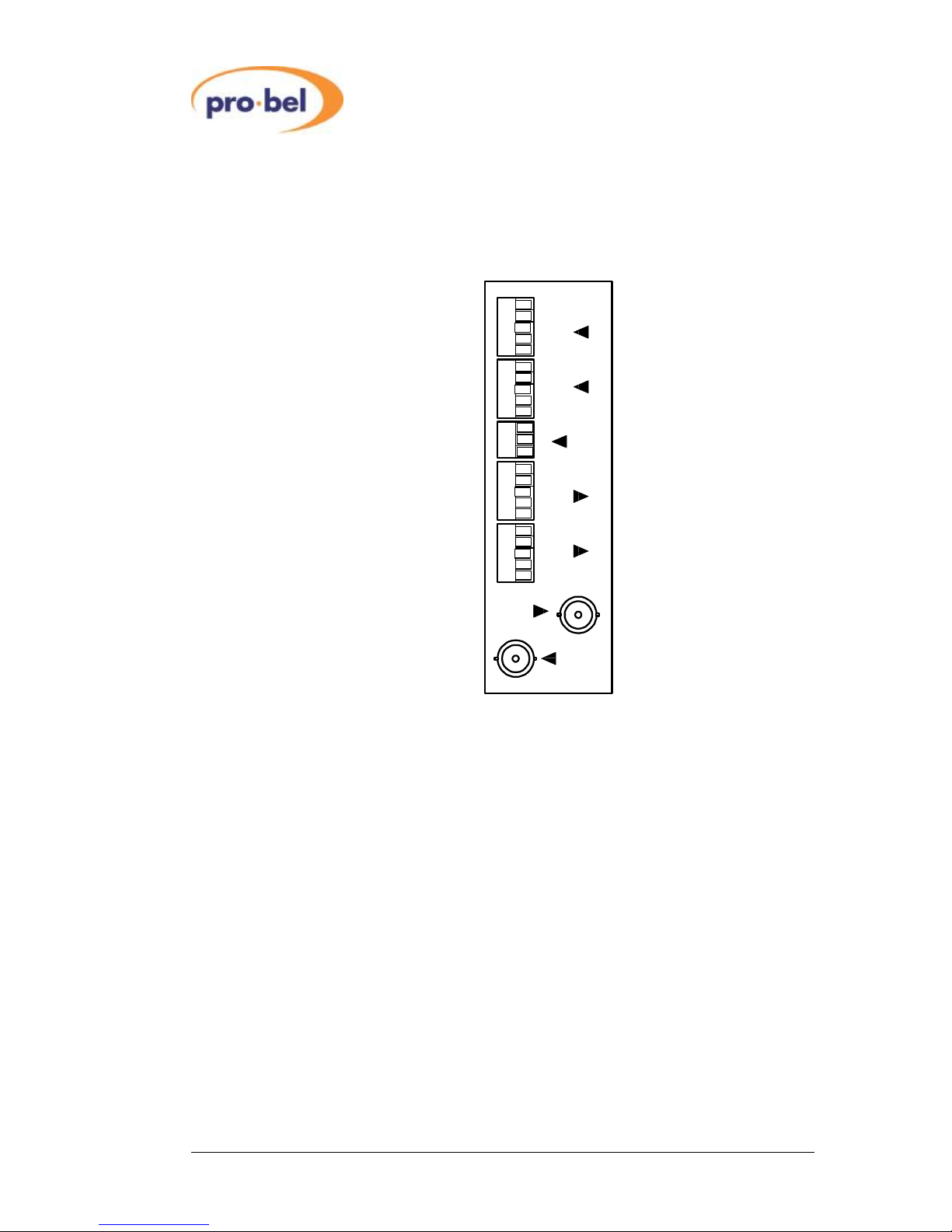
2.1 RearPanelConnections
The standard3UScrewterminalrearpanelisshownbelow.Other3U and 1Upanelvariants
withscrewterminaland/orBNC connectorsaresimilarlymarked.Table2.1describesthe
connectionstotheunitwhen thesepanelsareused.
NotesonTable2.1:
1.Tableentriesin italictext denotethe connectionstobe made when the inputor
output audiois analog.
2.Tableentries in regular textdenoteconnectionstobe madewhen inputoroutput
audiois AESdigital.
3.When inputoroutputaudioisdigital,certainconnectionsare reserved.Do not
connectanythingtotheseconnections.
4.Grounds/screens(S)areconnectedtochassison alloutputsandinputsand
shouldbeconnectedtoall cablescreenstominimizehumand noise.
5.Onunitswithanalogoutputoption,neither(+or-)output shouldbegrounded.
6.The TRACKinputacceptsapulsetrainofactivehigh TTL-levelpulsesateither
NTSCorPALframerate(33/40ms).The pulsesshouldbearePWMmodulated
indirect 1:1proportion totherequired delay.Inotherwordsthe pulsewidth(high)
inmillisecondsequalsthe required delay.Pulsewidthsshorterthan1msor
longerthan40msareignored bytheV1635.
Table2.2describesconnectionstothe unitwhen D-typepanelsareused.The V1635 is
designedtouseacommon rearpanelforallvariantsofthemodule.
VistekV1635V-100 24-bitAES Audio
VariableDelayModule
6 HU-V1635V-100
NotesonTable2.2:
1.No connectmeansdonotconnectthispintoanything.
2.Formodulesequipped withAESoutputs, bothpairsof outputsareavailableon D-
typerearpanels.ThesearedenotedasAESA1,AESA2etc.
L/AES
R
+
-
S
-
+
+
S
-
+
-
S
-
+
+
-
S
-
+
+
-
S
-
+
L/AES
R
L/AES
R
L/AES
R
AES
REF.
A
B
A
B
TRACK
VIDEO
REF

VistekV1635V-100 24-bitAES Audio
VariableDelayModule
Issue 8.0 7
Table2.1
DescriptionofV1635rear panelconnectionsforstandardrear panelassemblies
SIGNAL SOURCE COMMENTS
name
POWER
Rack PWRHeader
+15Vnominal(9
-
35V)at 10Wmax
DARTbus Rack DARTheader VistekDARTRackcontroller
A
3
(IN)
L/AES (+/-) ExternalAESsource AES3/AES3iddigitalinputforchannelpairA
Ext.Analog source
LAnalog input forchannelp
airA
R
(+/
-
)
DoNotConnect
Reserved
Ext Analog source
RAnalog input forchannelpairA
B
3
(IN)
L/AES (+/-) ExternalAESsource AES3/AES3iddigitalinputforchannelpairB
ExternalAnalog source
LAnalog input forchannelpairB
R
(+/
-
)
DoNotConnect
Reserved
ExternalAnalog source
RAnalog input forchannelpairB
A
4
(OUT)
L/AES (+/-) V1635 AES3/AES3iddigitaloutputforchannelpairA
V1635
LAnalog outputforchannelpairA
R
(+/
-
)
Donot Connect
Reserved
V1635
RAnalog outputforchannelpairA
B
4
(OUT)
L/AES (+/-) V1635 AES3/AES3iddigitaloutputforchannelpairB
V1635
LAnalog outpu
tforchannelpairB
R
(+/
-
)
Donot connect
Reserved
V1635
RAnalog outputforchannelpairB
AES
3
(IN)
ExternalAESreference
REF referencesource AES3/AES3iddigitalinputforreference
VIDEO
3
(IN)
Externalvideo
525/625lineanalog studiograde
referenceinput
REF referencesource
75
W
/Hi
-
Z
TRACK
3
(IN)
Externalvideo
TTL
-
levelPWMpulsetrainatPAL/NTSC
synchroniser framerate.Pulsewidth=delay

VistekV1635V-100 24-bitAES Audio
VariableDelayModule
8 HU-V1635V-100
Table2.2
DescriptionofV1635rear panelconnectionsforD-typerearpanelassemblies
D15FInputconnector
Pin Analog AES Pin Analog AES
1 Aleftin- AES Ain-
2 Arightin-Noconnect 9 Aleftin+ AES Ain+
3 GND GND 10 Arightin+ Noconnect
4 AES Ref in- AES Ref in- 11 GND GND
5 Bleftin- AES Bin- 12 AES Ref in+ AES Ref in+
6 Brightin- Noconnect 13 Bleftin+ AES Bin+
7 GND GND 14 Brightin+ Noconnect
8 GND GND 15 GND GND
D15FOutputconnector
Pin Analog AES Pin Analog AES
1 Aleftout- AES A1out-
2 Aright out-Noconnect 9 Aleftout+ AES A1out+
3 GND AES A2out- 10 Aright out+ Noconnect
4 GND Noconnect 11 GND AES A2out+
5 Bleftout- AES B1out- 12 GND GND
6 Bright out- Noconnect 13 Bleftout+ AES B1out+
7 GND AES B2out- 14 Bright out+ Noconnect
8 GND GND 15 GND AES B2out+
2.2 OutputWordlengthSetting
The digitalaudiooutputwordlengthisnormally24 bits.It maybesetto 20 bits by closing
jumperLK1.
2.3 VideoReference InputImpedance
The video referenceinputimpedanceis75Wwhen jumperLK3is closed.Itishigh
impedancewhen jumperLK3isopen tofacilitatevideoreferencedaisychaining.
2.4 AES Reference InputImpedance
The AES ReferenceInputImpedanceIs 110/75WWhenJumperLK4Is Closed.ItIsHigh
impedancewhen LK4isopen, facilitatingreferencedaisychaining. Daisychainscan include
up to4modules.
2.5 MIL/MOLAdjustment
OnV1635Voptionswithanalog inputstworotary HexSwitchesareprovided foradjusting the
MIL (Maximum Input Level)ofthe analog inputsforeachchannelpairAand B.MIL is
adjustablein1dBstepsfrom+14dButo+28dBu.

VistekV1635V-100 24-bitAES Audio
VariableDelayModule
Issue 8.0 9
OnV1635Voptionswithanalogoutputs,tworotary HexSwitchesareprovidedforadjusting
the MOL (Maximum Output Level)ofthe analog outputsforeachof the channelpairsAand
B. MOL isadjustablein1dBstepsfrom+14dButo+28dBu.
MIL/MOLsetting versusswitchpositionforbothanaloginputsand outputsisshowninthe
table below.
Switchsetting MIL/MOLfor0dBFS
0 +14
1 +15
2 +16
3 +17
4 +18
5 +19
6 +20
7 +21
8 +22
9 +23
A +24
B +25
C +26
D +27
E +28
F reserved
The figurebelowshowslocation ofalljumpersand switchesthatmaybe fitted across the
range ofV1635Vvariants.
Front Panel
RearConnector
LK1
LK3
LK4
B
B
A
A
MILswitches
MOLswitches
VistekV1635V-100 24-bitAES Audio
VariableDelayModule
10 HU-V1635V-100
3 Operation
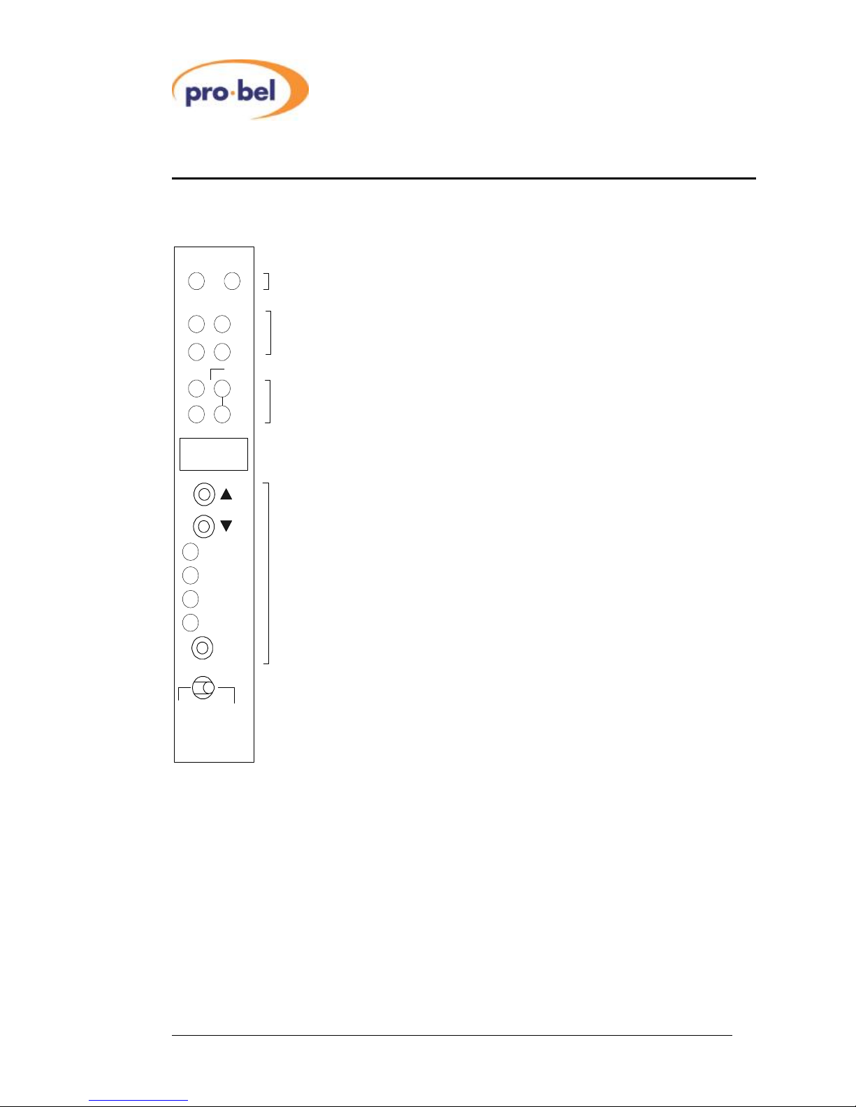
3.1 FrontPanelControlsand Indicators
REM +V
V1635V
Audio
Delay
RemoteControlAccess and Powerindicators
Sampling rateindicators
32k 44k1
48k
Rem Local
Parameter
Selection Controls
Delay
A/B Swap
Select
CharacterDisplay
7. 7. 7.
AES
Video
Ref.
SPS
Ref.
Referenceindicators
A
B
3.1.1 RemoteControl Access andPowerIndicators
The green V+LEDislitwhen the unit’son-boardpowersupplyisdelivering voltage.The
yellowREM LEDislitwheneverthe unitisaccessed bythe RackControllerforthe DART
remotesystem.
3.1.2 SamplingRateIndicators
TheseLEDsindicatethe sampling rateofthe AES digitaloutputs,asselected bythe
ParameterSelectionControls.Onvariantswithanalogoutputsthe LEDsshowthe internal
samplingrate.

VistekV1635V-100 24-bitAES Audio
VariableDelayModule
Issue 8.0 11
3.1.3 Reference Indicators
TheseLEDsindicatethe presentreferencesource,asselected bythe ParameterSelection
Controls.WhenFree-Running(internalcrystaloscillator)isselected,none oftheLEDsare
lit, and when an externalAES orVideo referenceisselected and ispresent, the appropriate
LEDwillbe lit continuously. Ifthe selected externalAES orVideo referencefails,the LEDwill
flashandthe V1635Vwill defaulttofree-runningmode until thereferencerecovers.
3.1.4 CharacterDisplay
Used fordisplayingparameterswhichhavenumericoralphanumericvalues.
3.1.5 ParameterSelectionControls
Theseareused forselectionof, and adjustmentof, operating parameterswhen the rem/local
switchissettolocal.
3.2 AdjustmentofOperatingParameters
3.2.1 General
The V1635Vhasthree pages (Page0,Page1 and Page2)ofpaneladjustmentmodes,
eachpage allowsadjustmentof one ormore parameters. Conceptuallythe procedureisnot
unlikesettingadigitalalarmclockorwatch.
·Paneladjustmentpagescan onlybe invoked ifthe REM/LOCAL switchon the panel
isset to LOCAL.
·Pressing the SELECT button on itsowninvokesthe paneladjustmentmodesof
Page0
·Pressing the SELECT button whileholdinginthe pbutton invokesthe panel
adjustmentmodesof Page1.The pbutton isanalogoustoa‘SHIFT’keyon a
computerkeyboardwhen selectingpagesof adjustment modes.
·Pressing the SELECT button whileholdinginthe qbutton invokesthe panel
adjustmentmodesof Page2.Theqbutton isanalogoustoan‘ALT’keyon a
keyboardwhen selectingpagesof adjustment modes.
·Onceanypanel adjustmentpage hasbeen selected,repeated pressing ofthe
SELECT button allowsthe usertoscrollthroughthe variousparametersavailable
on thepage.ArowofLEDsabovethe SELECT button indicateswhich
parameter ispresentlyselectedforadjustment.
·Foranygivenparameterselectedforadjustment, thevalueofthe parametermay
be increased ordecreased bypressing the por qkeysrespectively. The value
ofthe parameterisindicated eitheron the characterdisplayorthe respectivesets
ofLEDsabovethecharacterdisplay.
·Holdingthe or por qbuttonsdownwillcausethevalue of the parametertoauto
incrementandautodecrementrespectively.The longerthebutton ishelddown,
thefastertherateof autoincrement orautodecrement.

VistekV1635V-100 24-bitAES Audio
VariableDelayModule
12 HU-V1635V-100
·Onceaparameterhasbeen adjusted tothedesired value,the PanelAdjustment
mode isexited bypressing the SELECT buttonuntil allfourofthe LEDsabove
the SELECT buttonareoff.
·The V1635hasnon volatilememory storage thatautomaticallysavesthe values
ofallthe operating parameterssetin LOCAL modesothaton power-up orwhen
the REM/LOCAL switchisswitchedfrom REM to LOCAL,thelastsettingsmade in
LOCAL modewillbe restored. Parameteradjustmentstakeeffect immediatelybut
areonlysaved tonon-volatilememoryon the V1635 whenthe adjustmentmode
isexited.
Thefollowing tableindicatestheavailablePanelAdjustmentmodesonthetwopages.
LEDindicator Page0 Page1 Page2
Parameter Adjustrange Parameter Adjustrange Parameter Adjustrange
Delay Delay 0msto2500ms Test Tone A,B Off/A,B on Input GainA1 {-16dB...+15dB}
Ref. Reference Free, AES, Video FineDelay {0...47}samples Input GainA2 {-16dB...+15dB}
SPS Samplerate 32, 44.1, 48kHz - Input GainB1 {-16dB...+15dB}
A/B Swap A/B Swap Normal/Swapped - Input GainB2 {-16dB...+15dB}
3.2.2 DelayAdjustment
Afixeddelaymaybeappliedtoallfouranalog channelsasagroup and the presentsetting
maybe seen on the characterdisplayasanumberwhen Page0 PanelAdjustmentmode
hasbeen entered and Delay selectedasaparameter.
·By PanelSelection the delayvalue maybe adjusted from0msto1.25 seconds.
Adjustmentisin1msstepsfrom0to1250ms. From0to999ms, the delayvalue
isdisplayed inmsand from1.0supwardsitisdisplayedinsecondsto10ms
resolution,i.e.1.xx.Adecimalpointafterthe leastsignificantdigitindicatesa
value ofdelaybetween the10msdisplayvalues.
·TheDART interfacecancontrolthedelayin1msstepsacross the range.
·Theminimumthroughputdelayofthe V1635isless than2ms.
Note:changingtheadjustabledelay will causeatemporary disruptionofaudiofora
timenotless thanthedifferencebetweenoldand newdelay settings.
3.2.3 Reference Setting
The referencesourcemaybe selected and the present setting maybe seen on the Ref LEDs
when Page0 PanelAdjustmentmode hasbeenentered and Ref. selected asaparameter.
Theselectableoptionswill dependontheV1635Vvariantasfollows:
·Oncardswithanalogoutputs,only FreeRun referencemaybe selected (allRef
LEDsoff).
·Oncardswithdigitaloutputsand analog inputs, the referencemaybeset to Free
Run, AES or Video whichcorrespond toRef LEDsnone,AESand Videobeing lit
respectively.

VistekV1635V-100 24-bitAES Audio
VariableDelayModule
Issue 8.0 13
·Oncardswithdigitaloutputsanddigitalinputs,eitherofthe twoAESinput
channelpairsmayalsobe used asreferenceand the optionsbecome A, B, Free
Run, AES,or Video
·Ifan externalreferencefails,the appropriateLEDwillflashand the V1635Vwill
defaultto Free Run mode withreferencefromtheinternalcrystaloscillator.
Videoreferenceisonlyavailable at48KHz,AESref,Inp.Arefand Inp.Brefareavailableat
32kHzand48kHz, andFreeRunrefisavailableatall samplerates.
3.2.4 SampleRateSelect
The samplerateof the V1635Vmaybe selectedand thepresentsettingmaybeseen onthe
SPS LEDswhen Page0 PanelAdjustmentmode hasbeen enteredand SPS selected asa
parameter.Theselectable optionswill dependontheV1635Vvariantasfollows:
·Oncardswithanalog outputs,the SPSreferstotheinternal samplerateand is
fixedat 48kHz.
·Oncardswithdigitaloutputs,the SPS referstothe internaland outputsample
rateandmaybe setto 32kHz,44.1kHz or 48kHz.
3.2.5 A/BSwap
AtranspositionofAESAand AESBinputsmaybe invoked and thepresentsettingmaybe
seen on the characterdisplayasalettercombination when Page0 PanelAdjustmentmode
hasbeen entered and A/BSwap selected asaparameter.
·When inputchannelpairsAandBarerouted tooutputchannelpairsAand B
respectively, the A/BSwap parameteris Normal andisindicated on the character
displayas A-A.
·When inputchannelpairsAand Baretransposed tooutputchannelpairsBand A
respectively,the A/BSwap parameteris Swapped andisindicated on the
characterdisplayas A-b.

VistekV1635V-100 24-bitAES Audio
VariableDelayModule
14 HU-V1635V-100
3.2.6 TestTone
Atesttone of 997Hzmaybe invoked on bothchannelsofeitherorbothAand Bchannelpairs
and the present settingmaybe seen on the characterdisplayasanumbercombination when
Page1 PanelAdjustmentmodehasbeen entered and TestTone selectedasaparameter.
ThetablebelowexplainstheavailableTestToneselections
The testtone isthe samefrequency (±1Hz)forall availablesamplerates,buttheoutput
amplitude dependsontheV1635Vvariantasfollows:
·Oncardswithdigitaloutputs,thetesttoneis-18dBFS.
·Oncardswithanalog outputsthetesttone is0dBu.
3.2.7 FineDelay
Anadditionaldelayofup to1msmaybe addedtothe delayselected in 3.2.2bymeansofthe
Fine DelayControl. Thiscontroladdsdelayinincrementsofone audio sampleperiod,from0
to47 samples.Theabsolutetimedelaywilldepend onthe samplerate-at48kHzitis
20.83ms.Thismode isusefulforsetting up amultichannelaudio program(suchasDolby) so
that all the constituent signals(whichmaybe subject todifferentpaths) areinphase.
The paneldisplayforthe Fine Delaycontrolisdxx,wherexx isanumber-of-samplesdelay
effected.
3.2.8 InputGain
Gainon eachofthe fourinputsA1,A2,B1,B2maybe varied inthe range –16dB..+15dB.
The gainsareapplied inthe signalchainbeforethe A-Bswitchand areinvoked‘on the fly’.
The moduleisshipped with0dBgainsseton all inputs.The presentsetting ofgainmaybe
seen on the characterdisplayasadeciBelnumberwhen Page2 PanelAdjustmentmodehas
been entered and InputGain A1 throughInput GainB2 selectedasaparameter.Using the
DARTinterface,remotecontrolsoftwarecanbe tailoredtoapply‘ganged pot’gainsif desired.
DisplayTestTones
00 Notesttonesselected
10 Test toneon channelpairAonly
01 Test toneon channelpairBonly
11 Test toneon bothchannelpairs

VistekV1635V-100 24-bitAES Audio
VariableDelayModule
Issue 8.0 15
4 DartInterface
4.1 General
The V1635 isaClass 4DARTmodulewithaserialEEPROMforreading and writingcard
detailsthrough the DARTbusinthe samemannerasotherV1600 range cards.Inaddition
the unithasseveralread and writeregisters,detailsofwhichmaybe found indocument
scsm1635.doc.Settingsofoperating parametersmadeviathe DARTinterfacearenot
stored innon-volatilememorybytheV1635,andNVmemory inthe remotecontrolsystemis
used forstoringthesesettings.
This manual suits for next models
5
Table of contents
Popular Control Unit manuals by other brands


Minebea
Minebea MPC-201B-25 instruction manual

Moxa Technologies
Moxa Technologies ioLogik E1261W-T user manual

RTL
RTL Scorpion II C-90 MASH TL-3 Vertical TMA Assembly Manual and Mounting Instruction Guide

Mankenberg
Mankenberg DM 652 ATEX H2 manual

Armstrong
Armstrong GD-10 Installation and maintenance instructions

Fleck
Fleck 3150 Service manual