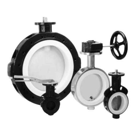
Series NKS/F, NKSP/F, NKL/F, NKLP/F Page 2
9520-020-en Revision 16
TM 10207 Edition 05/2020
List of Contents
List of Contents ................................................ 2
Relevant documents ........................................ 3
1Technical data............................................. 3
1.1 Overview of sizes ...........................................4
1.2 Type plate, CE and body markings ..............4
1.3 Tightening torques..........................................5
1.4 Dimensions .....................................................6
1.5 Flow rate value kv100 [m³/h] .........................6
1.6 Weights (ca. kg)..............................................7
1.7 Pressure-temperature diagram .....................7
1.8 Actuating torques ...........................................8
1.9 Cavitation coefficient z for 75% duty ............8
2Notes on safety ........................................... 8
2.1 Intended use ...................................................8
2.2 For the customer / operator...........................9
2.3 Improper operation.........................................9
3Safety notes for applications in potentially
explosive areas based on the Directive
2014/34/ EC (ATEX)..................................... 9
3.1 Intended use ...................................................9
4Safety note for valves, certified to Clean
Air Act (TA Luft) ........................................ 10
5Transport, storage and disposal............. 11
5.1 Storage..........................................................11
5.2 Transport preparations ................................11
5.3 Return consignments ...................................11
5.4 Transport securing .......................................11
5.5 Disposal.........................................................12
6Installation ................................................. 13
6.1 Installation possibilities ................................13
6.2 Flange caps and gaskets.............................13
6.3 Direction of flow and installation position..13
6.4 Installation .....................................................13
6.4.1 Additional advice for shut-off and control
butterfly valve with actuator............................... 13
6.5 Grounding .....................................................13
7Operation ................................................... 14
7.1 Initial commissioning ................................... 14
7.2 Improper operation and their consequences
................................................................... 14
7.3 Shutdown...................................................... 14
7.3.1 Additional advice for shut-off and control
butterfly valve with actuator ............................... 14
8Malfunctions .............................................. 14
9Maintenance .............................................. 15
9.1 Notes on assembly ...................................... 15
9.1.1 Safety stuffing box...............................................15
9.2 Valve actuation............................................. 15
9.2.1 Actuated with lever ..............................................15
9.2.2 Actuated by means of worm gear .....................16
9.2.3 Remotely actuated .............................................. 16
9.2.4 Required breakaway torque...............................16
9.3 Options.......................................................... 16
9.3.1 Safety stuffing box...............................................16
9.3.2 Monitoring connection.........................................16
9.3.3 Proximity switch ...................................................16
9.4 Tests ............................................................. 16
10 Drawings .................................................... 17
10.1 Legend.......................................................... 17
10.2 Sectional drawing NKS/F, DN 50 –150, 2"–
6" ................................................................... 18
10.3 Sectional drawing NKS/F, DN 200-400, 8"-
14" ................................................................. 19
10.4 Sectional drawing NKL/F, DN 50 –150, 2"–
6" ................................................................... 20
10.5 Sectional drawing NKL/F, DN 200-400, 8"-
14" ................................................................. 21
10.6 Worm gear.................................................... 22
10.7 Actuator......................................................... 22
10.8 Option safety stuffing box ........................... 23
10.9 Dimensional drawing NKS/F with lever
assembly....................................................... 24
10.10 Dimensional drawing NKS/F with worm
gear ............................................................... 25
10.11 Dimensional drawing NKSP/F ............... 26
10.12 Dimensional drawing NKL/F with lever
assembly....................................................... 28
10.13 Dimensional drawing NKL/F with worm
gear ............................................................... 29
10.14 Dimensional drawing NKLP/F................ 30
