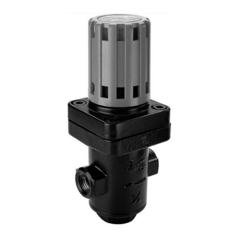
Armstrong GD-10 User manual
Other Armstrong Control Unit manuals
Armstrong
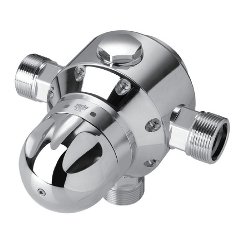
Armstrong 425 Instruction Manual

Armstrong
Armstrong 3031S Instruction Manual
Armstrong
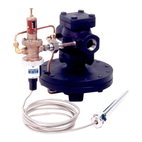
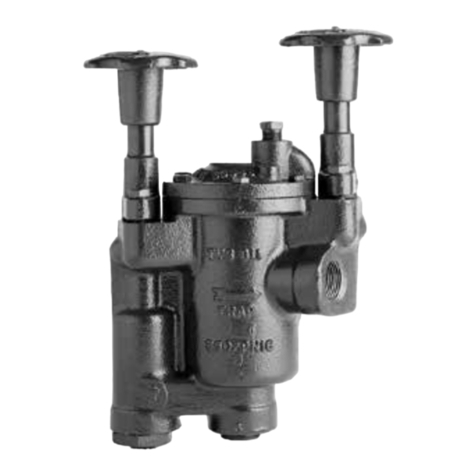
Armstrong OB-2000PT Integral User manual
Armstrong
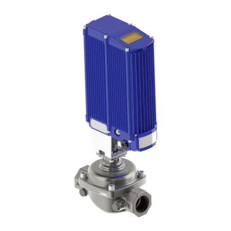
Armstrong TVS-800 Series User manual
Armstrong
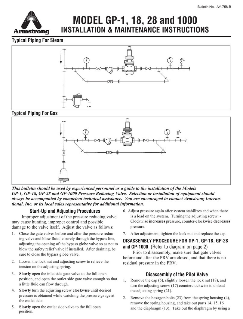
Armstrong Emech F2 Instruction manual
Armstrong
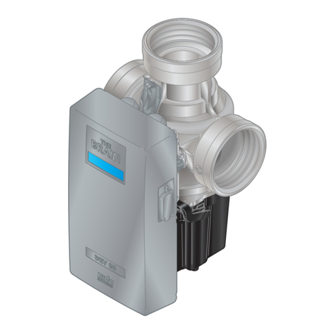
Armstrong GP-1 Installation and operating instructions
Armstrong
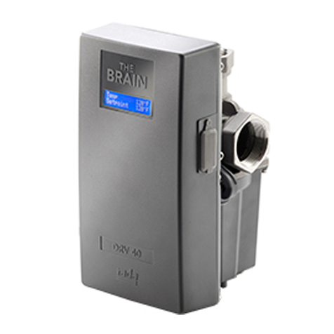
Armstrong BRAIN DMC80 User manual
Armstrong
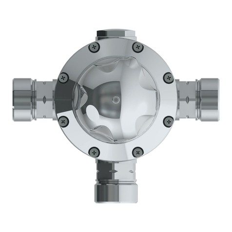
Armstrong DRV40 User manual
Armstrong
Armstrong Rada 320 Instruction Manual
Armstrong
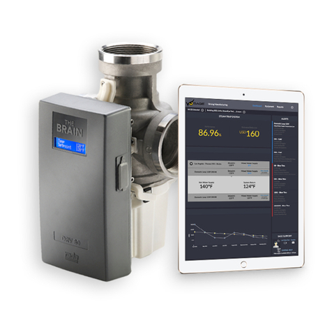
Armstrong Emech F3 Instruction manual
Armstrong
Armstrong The Brain DRV80 User manual

Armstrong
Armstrong TVS 4000F User manual
Armstrong
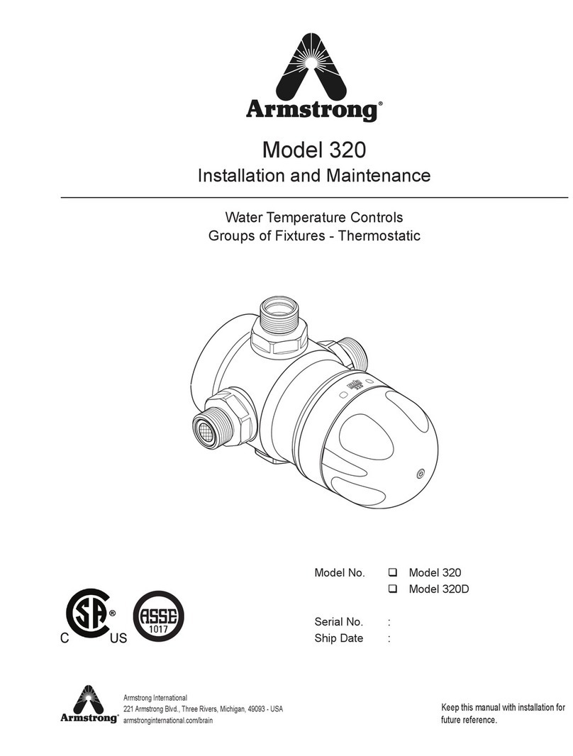
Armstrong 320 Instruction Manual
Armstrong
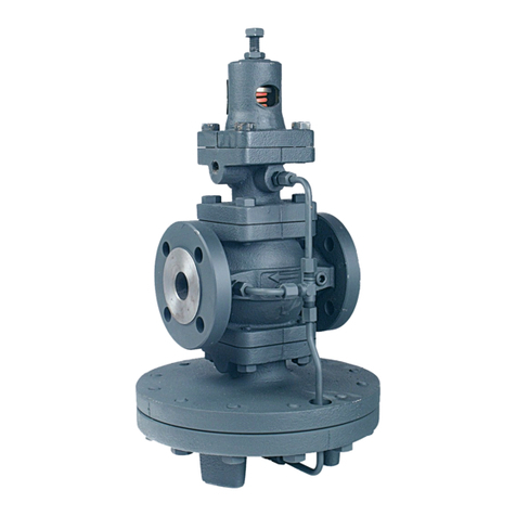
Armstrong GP-2000 User manual
Armstrong
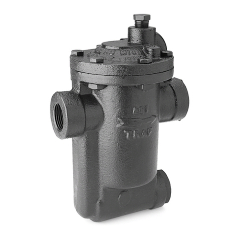
Armstrong 880 Series Technical specifications
Armstrong
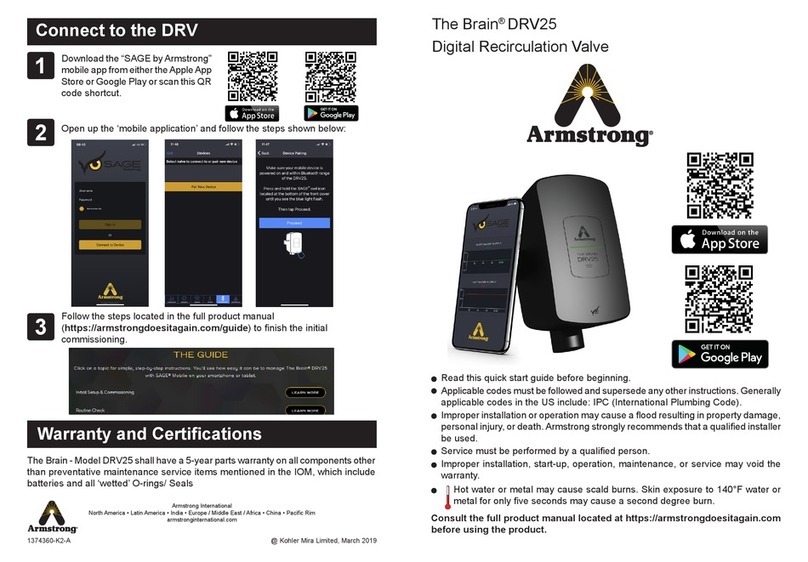
Armstrong The Brain DRV25 User manual
Armstrong
Armstrong CD72SR User manual

Armstrong
Armstrong 880100-002 User manual
Armstrong
Armstrong 1-AV User manual

Armstrong
Armstrong A Series User manual
Popular Control Unit manuals by other brands

Festo
Festo Compact Performance CP-FB6-E Brief description

Elo TouchSystems
Elo TouchSystems DMS-SA19P-EXTME Quick installation guide

JS Automation
JS Automation MPC3034A user manual

JAUDT
JAUDT SW GII 6406 Series Translation of the original operating instructions

Spektrum
Spektrum Air Module System manual

BOC Edwards
BOC Edwards Q Series instruction manual

KHADAS
KHADAS BT Magic quick start

Etherma
Etherma eNEXHO-IL Assembly and operating instructions

PMFoundations
PMFoundations Attenuverter Assembly guide

GEA
GEA VARIVENT Operating instruction

Walther Systemtechnik
Walther Systemtechnik VMS-05 Assembly instructions

Altronix
Altronix LINQ8PD Installation and programming manual
