Pro-face GLC100-LG41-24V User manual

WARNINGS
When Designing your GLC System:
- Be sure to design your GLC control system so that in the event of a main power
supply failure or a GLC accident, the user system’s overall safety integrity will be
maintained. If this is not done, incorrect output signals or a GLC malfunction may
cause an accident.
(1) Interlock circuits, etc. designed to interrupt or oppose normal machine movement
(i.e. Emergency Stop, General Protection, forward and reverse rotation, etc.), as
well as those designed to prevent machine damage (i.e. for upper, lower and traverse
movement limit positioning, etc.) should all be designed to be located outside of the
GLC.
(2) Whenever the GLC generates a “Watchdog Timer Error”, GLC operation will halt.
Also, when Errors occur in Input/Output control areas that the GLC cannot detect, it
is possible for unexpected movement to occur in those areas. As a result, for the
purpose of preventing unsafe machine movement, a “Failsafe Circuit” should be
created which is completely external to the GLC.
(3) If an problem arises with an external unit’s relay or transistor, causing an output
(coil) to remain either ON or OFF, a major accident can occur. To prevent this, be
sure to set up external watchdog circuits that will monitor vital output signals.
- Design a circuit that will supply power to the GLC’s I/O unit before starting up the
GLC. If the GLC’s internal program enters RUN mode prior to the I/O unit’s load
control power turning ON, an incorrect output (signal) or malfunction could cause an
accident to occur.
- Design a user program that will ensure the safety of the user’s system, in the event of
a GLC display or control error, or in the event of either a data transmission error or
power failure between the GLC and a connected unit. These types of problems can
lead to an incorrect output (signal) or malfunction, which could thereby cause an
accident to occur.
- Do NOT use GLC touch panel switches to perform life-related or important accident
prevention operations. These operations should be performed by separate hardware
switches to prevent operator injury and machine damage.
Wiring Warnings:
- To prevent electric shock or equipment damage, prior to installing or wiring the GLC,
confirm that the GLC’s power cord is unplugged from the power supply.
- After completing any GLC wiring work, be sure the terminal block’s protective plas-
tic cover is reattached. If this cover is not reattached, an electric shock could easily
occur.
- High voltage runs through the GLC. Except for changing the backlight, do NOT
attempt to open the GLC, since there is a possibility of an electric shock.
- Do not use power levels with the GLC that are outside of the GLC’s specified power
range. Doing so may cause a fire, electric shock or damage the GLC.
- Do not operate or store the GLC in areas where flammable gasses are present, since
operating the GLC may cause an explosion.
DANGERS

Operation and Maintenance Warnings:
- Never touch a live power terminal. This could cause a shock or machine malfunction.
- Due to the danger of an electric shock, confirm that the GLC’s power cord is un-
plugged before either cleaning the GLC or attaching/detaching the power terminal
screws.
- When replacing the GLC’s backlight, be sure to unplug the unit’s power cord to
prevent a shock, and wear gloves to prevent being burned.
- The GLC uses a lithium battery for backing up its internal clock and control memory
data. If the battery is incorrectly replaced (i.e. the + and - sides are reversed), the
battery may explode. Therefore, before changing the battery, Digital recommends
that you contact your local GLC distributor for battery replacement instructions.
- Do not attempt to modify the GLC’s internal parts or wiring in any way, since this
may lead to either a shock or fire.
CAUTIONS
Wiring Layout Cautions:
Be sure that all GLC input/output signal lines are isolated from all power wiring or
power cables, via a separate wiring duct. This is to prevent excessive noise, which can
cause a unit malfunction.
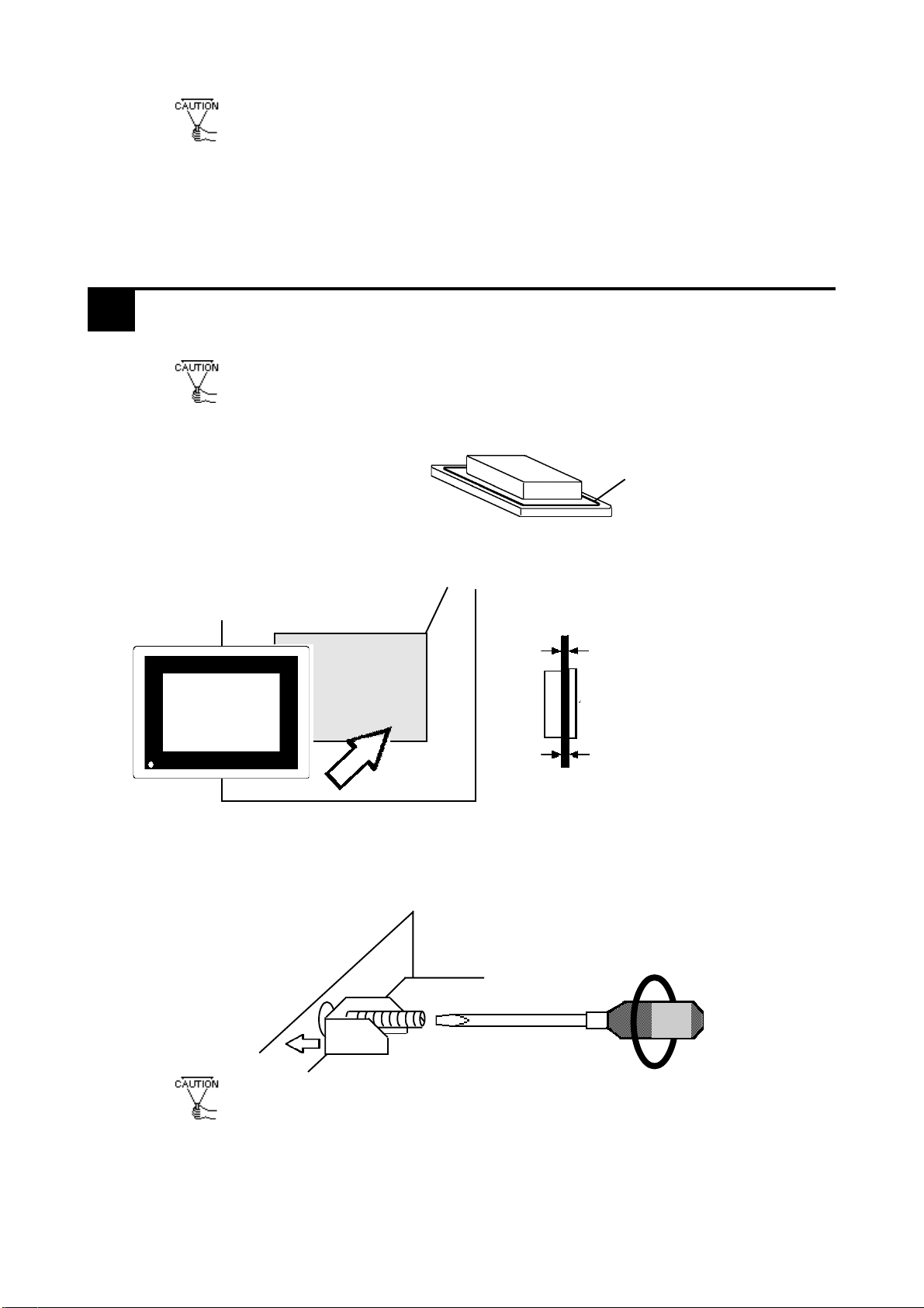
Installation Cautions:
- When attaching the I/O unit to the GLC, be sure that all the I/O unit’s attachment
screws are used and the unit is securely attached to the GLC. If the I/O unit is not
attached securely in place, the I/O unit may be damaged if it falls off the back of the
GLC, or a system-related malfunction or accident may occur due to I/O data signal
problems.
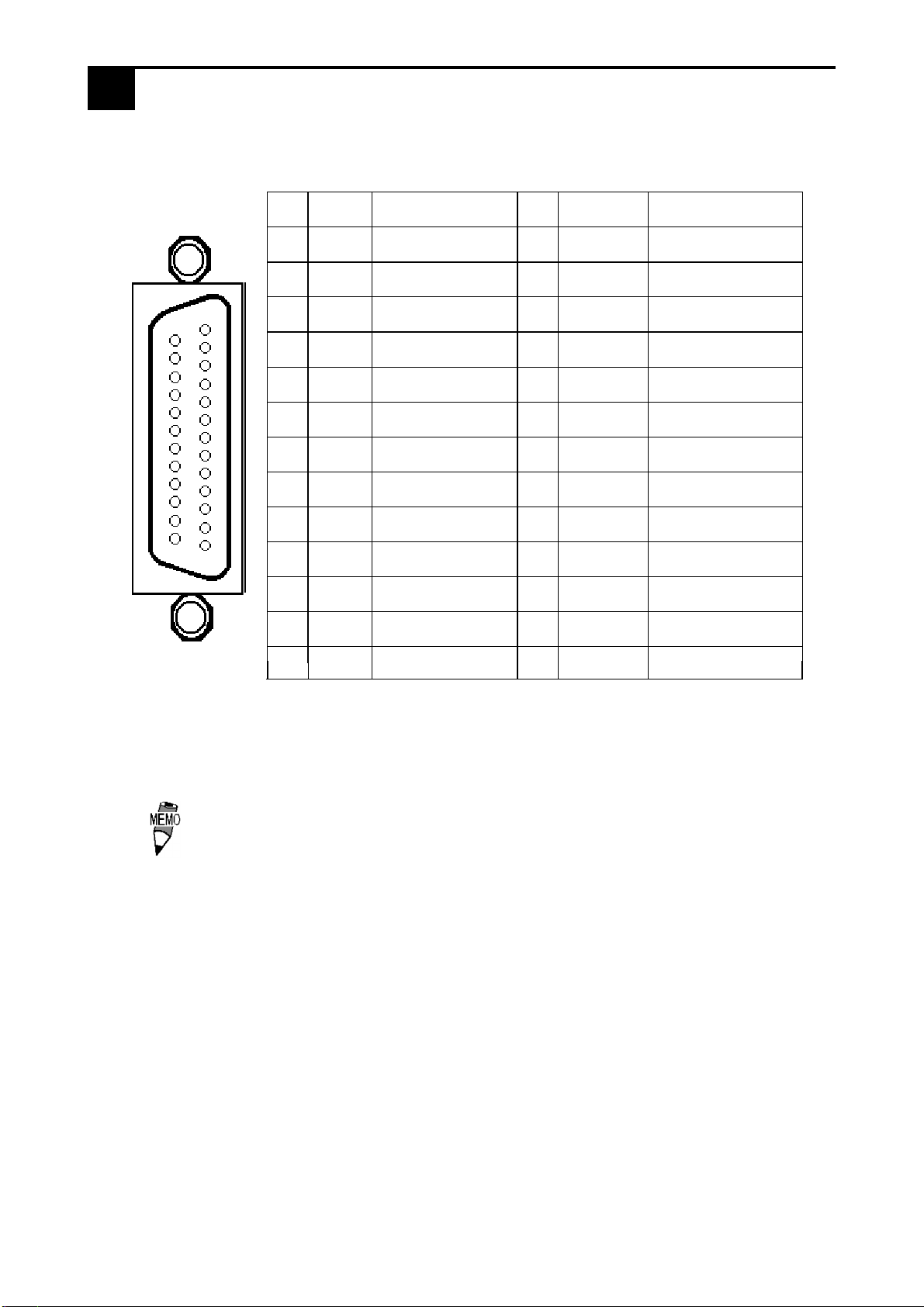
- Be sure any data cable attached to the GLC’s connector is securely attached. If the
cable and connector pins do not all make complete contact, incorrect input or output
signals can result.
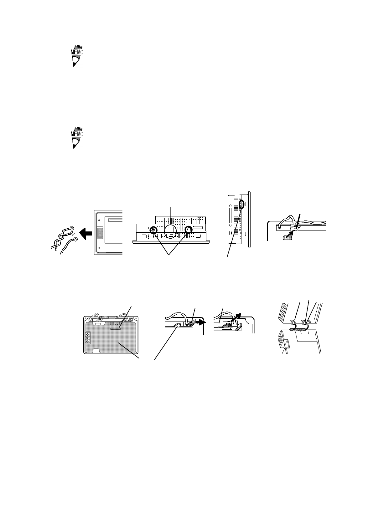
General Wiring Cautions
- To prevent shocks or malfunctions, GLC’s FG (earth) wire should be grounded ac-
cording to the following:
1) A maximum grounding resistance of 100 W or less.
2) A grounding wire of 2mm2or larger should be used.
- The GLC’s wiring should be checked to confirm both that the operating voltage and
wiring terminal locations are correct. If either the voltage or the wiring terminal loca-
tions are incorrect, it can cause a fire or accident.
- Be sure to secure all wiring terminal screws in place with the designated torque.
Screws and terminals that become loose can cause a short circuit, fire or accident.
- Be sure that metal filings or wiring remnants do not fall inside the GLC, since they
can cause a fire, accident, or malfunction.
GLC Operation and Maintenance Cautions
- Be sure to read the GLC’s manual and on-line help information carefully before per-
forming program changes, forced output, or utilizing the RUN, STOP or PAUSE
commands while the GLC is in operation. Mistakes concerning the use of these items
can cause a machine accident or damage.
GLC Unit Disposal Cautions
- The GLC unit should be disposed of in a manner appropriate to the user country’s
industrial machinery disposal standards.

The GLC100-LG41-24V and GLC100-SC41-24V are UL/c-UL(CSA) recog-
nized products. (UL file No.E182139)
GLC conforms as a component to the following standards:
•UL508
Industrial Control Equipment
•UL1604
Electrical Equipment for Use in Class I and II Division 2 and Class III
Hazardous (Classified) Locations
•CAN/CSA-C22.2, Nos.142, and 213-M1987
Standard for Safety of Information Technology Equipment, including
Electrical Business Equipment
GLC100-LG41-24V (UL Registration Model : 0980017-01)
GLC100-SC41-24V (UL Registration Model : 0980017-02)
• The GLC should be installed in the front face of a metal panel.
• If the GLC is installed so as to cool itself naturally, be sure to install it in
a vertical panel. Also, be sure that the GLC is mounted at least 100mm
away from adjacent structures and other equipment, otherwise, the heat
generated by the GLC's internal components may become higher than
that allowed by UL standard requirements.
Installation and operation instructions are provided with each GLC. These
installation instructions contain the following statements.
1.Power, input and output (I/O) wiring must all be in accordance with Class I,
Division 2 wiring methods, Article 501-4 (b) of the National Electrical Code,
NFPA 70, or as specified in Section 18-152 of the Canadian Electrical Code
for units installed within Canada, and in accordance with that location's au-
thority.
2.Suitable for use in Class I, Division2, GroupsA, B, C and D hazardous loca-
tion, or nonhazardous locations only.
3.WARNING: Explosion hazard-substitution of components may impair suit-
ability for Class I, Division2.
4.WARNING: Explosion hazard-do not disconnect equipment unless power
has been switched off or the area is known to be nonhazardous.
5.WARNING: Explosion hazard-when in hazardous locations, turn off power
before replacing or wiring modules.
UL/C-UL(CSA) Approval
CE Marking
GLC100-LG41-24V,GLC100-SC41-24V are CE marked , EMC compliant
products.These units also conform to EN55011 class A , EN50082-2 di-
rectives.

The following items are included in the GLC's package. Prior to using the
GLC, be sure to confirm that all the parts shown below are present.
This unit has been carefully packed, with special attention to quality. How-
ever, should you find anything damaged or missing, please contact your
local GLC distributor immediately.
Package Contents
User's Manual
(Sold Separately)
GLC100 User’s Manual
GLC Option Items
Logic Program Development soft-
ware (Sold Separately)
Pro-Control Editor
GLC Unit
( GLC100-LG41-24V / GLC100-SC41-24V )
Operation Instructions (1 )
( this sheet )
Installation fasteners ( 4 pcs )
Operation
Instructions
Digital
(GLC100-MU41)
(Japanese Version Only)
Digital
GLC100
User's Manual
(GLCCNT-ED01J-V10)
(Japanese Version Only)
Pro-Control
Editor

The GLC's part names and their functions are explained below.
A:Display
Shows display screens and Host data.
GLC100-LG41-24V Monochrome LCD
GLC100-SC41-24V STN-type color LCD
B:Touch Panel
Performs screen change operations and
triggers the sending of data to the PLC.
C:Power Lamp
Lights when the GLC's power cord is con-
nected to the power supply.
D:Power Input Terminal Block
Provides power input and grounding termi-
nals for GLC's AC power cord.
E:Expansion Interface
Used for connecting expansion units to the
GLC.
F:Serial Interface
RS-232C, RS-422 (Serial) interface. Con-
nects the GLC to the Host.
G:Tool Connector
Connects the Screen Data Downloading
Cable, or Bar Code Reader to the GLC.
A,B
C
1Names and Functions of GLC Parts
The GLC100-LG41-24V and GLC100-SC41-24V unit dimensions are as
follows.
D FE G
2Dimensions
Unit:mm
Top View
Side View
57
5
123
155.5
170.5
Front View
138

14
25 13
1
SIO
This serial port is used for the GLC's RS-232C and RS-422 interface
cables.
Recommended Connector : Dsub 25 pin plug XM2A-2501 <made by OMRON Corp.>
Recommended Cover : Dsub 25 pin CoverXM2S-2511 <made by OMRON Corp.>
Jack Screw XM2Z-0071 <made by OMRON Corp.>
Recommended Cable : CO-MA-VV-SB5P X 28AWG <made by HITACHI Cable Ltd.>
•When creating a cable, please be aware of the following:
<For RS-422 Connections>
•The following pairs of pin #’s must be connected to each other
...#18 (CSB) <-> #19 (ERB)
...#21 (CSA) <-> #22 (ERA)
•When connecting the RS-422 cable and the #9 (TRMX) and
#10 (RDA) points, a termination resistance of 100Ωis added
between RDA and RDB.
•When the GLC is set as a Memory Link type and the cable type
is RS-422, a 4-line system must be used.
<For RS-232C connections>
•Do not connect #9 (TRMX), #10 (RDA), #11 (SDA), #15 (SDB),
#16 (RDB), #18 (CSB), #19 (ERB), #21 (CSA), and #22 (ERA).
Pin
#Signal
Name
Condition
Pin
#Signal
Name
Condition
1 FG Frame ground 14 VCC
5V
±
5% output
0.25A
2SD
Send data
(RS-232C) 15 SDB Send data B
(RS-422)
3RD
Receive data
(RS-232C) 16 RDB Receive data B
(RS-422)
4RS
Request send
(RS-232C) 17 NC No connection
5CS
Clear send
(RS-232C) 18 CSB Clear send B
(RS-422)
6 NC No connection 19 ERB Enable receive B
(RS-422)
7
GND
Signal ground
20
ER
Enable receive
(RS-232C)
8CD
Carrier detect
(RS-232C) 21 CSA
Clear send A
(RS-422)
9TRMX
Termination
(RS-422) 22 ERA Enable receive A
(RS-422)
10 RDA Receive data A
(RS-422) 23
RESERVED
Reserved for future
use
11 SDA Send data A
(RS-422) 24 NC No connection
12 NC No connection 25
RESERVED
Reserved for future
use
13
NC
No connection
ALRMOUT
ALRMGND
ExtemalAlarmOutput
ExtemalAlarmGround
BUZZEROUT
BUZZERGND ExtemalBuzzerOutput
ExtemalBuzzerGround
13
3Serial Interface

Cut a hole in the panel, and install the GLC into the panel's front face.
Attach the Installation Fasteners from the inside of the panel.
Tighten all installation fasteners with a screwdriver.
To create a waterproof seal, a force of 0.5-0.6N•m is required.
Panel GLC unit 6
7
Under 4-R3
1.6 mm to 5 mm
Panel thickness
Unit: mm
Tightening the screws with too much force can damage the GLC.
156
123.5
Rear of GLC
Gasket
Before installing the GLC, be sure that the moisture resistant
gasket is attached securely to the unit.
4Installation
Be sure to connect this unit’s SG/GND (Signal Ground) terminal
to the other unit’s Signal Ground terminal. If necessary, you may
also need to connect the FG terminal to the other unit’s FG ter-
minal depending on the type of the other unit you use.
This unit’s RS-485(RS-422) Port is not isolated, therefore, it is
crucial that you connect the SG/GND (Signal Ground) terminals.
If this is not done, the RS-485(RS-422) circuit may be damaged.
+1
-0
+1
-0

*1 Recommended Ring Terminals: V2-MS3 (made by JST)
Use the following steps when connecting the Ring Terminals.
1. Confirm that the Power Cord is unlugged from the power supply.
2. Remove the Power Input Terminal Block's plastic cover.
3. Remove the screws from the 3 terminals to be used and align the terminals.
Then, re-insert the screws and tighten them in place.
(Be sure the wires are correctly connected)
•The torque necessary for tightening the screws is from 0.5 - 0.6
N•m.
•To avoid the possibility of an electric shock, be sure the Power Cord is
unplugged from the power outlet prior to connecting the power cord's power
terminals to the GLC.
•The GLC100-LG41-24V and GLC100-SC41-24V can only use DC24V in-
put. Any other input voltage can damage the GLC and its power supply.
•Since the GLC has no power switch, be sure to use a breaker type switch.
•To prevent a short from occurring when the ring terminals
become loose, be sure to use sleeved ring terminals.
Ring Terminals*1
+ - FG +
-
FG
Rear of GLC
Power Input
Terminal Block
When the FG terminal is connected, be sure the wire is
grounded. Not grounding the GLC unit will result in excess
noise and vibration.
• Wherever possible, use thick wires (max. 2 mm2) for power
terminals, and twist the wire ends before attaching the ring ter-
minals.
•Be sure to use the following size Ring Terminals.
5Wiring
Under
6.0 mm
Over φ3.2 mm
WARNING

•From the FG terminal at the rear side of GLC unit, be sure to use exclu-
sive type grounding (resistance of less than 100 Ω).
•GLC input and Output signal lines must be separated from the power
control cables used for any and all operation circuits.
•If this is not possible, use a shielded, grounded cable.
•Before changing the Backlight, be sure the power cord has been discon-
nected from the power supply
•While the unit is still hot, be sure to use gloves to prevent burns.
•Do not touch the backlight area while the unit is still ON, since high voltage
runs through that area.
•When the GLC's power cord has just been unplugged, the unit is still very
hot. Be careful not to be burned.
•Check that you have the proper Backlight for your specific GLC-
100 model.
•When attaching an option unit to the GLC, be sure to follow the option
unit's operation instructions.
GLC Backlight Model
GLC100-LG**
GLC100-SC** GP370-BL00-MS
When changing the backlight, be sure to wear gloves and use the fol-
lowing steps.
1. Unplug the GLC's power cord from the power supply.
2. Detach the power cord from the GLC. (A)
3. With a screwdriver, unfasten the two screws on the top face of the
unit. Press down the top center section to confirm that the cover's
catch is released. (B)
4. Insert a screwdriver into the hole at the side of the unit.Then, hold the
GLC with one hand and turn the screwdriver to open up the unit from the
top. (C)
5. Unplug the Backlight's connector. Do not shift or remove the GLC's inter-
nal pad while pulling out the backlight. (D,E)
6Grounding Precautions
7Input/Output Signal Line Precautions
8Replacing the Backlight
WARNING

7. Insert the new Backlight, and attach its connector.
8. As shown in the diagram, insert the GLC case's positioning tabs into
the alignment holes, close the covers, and fasten the two top-face
attachment screws.(G)
•When reconnecting the GLC's covers, be careful not to pinch
any of the backlight wiring between the covers.
6. Push the connector clip to the right and pull out the backlight. (F)
•Do not move the clip to the left when removing the back light,
since it may break off.
Power Cord
BC
Connector
A D
Internal Pad
G
F
Clip Backlight
Connector
EPositioning
Tabs
Center
Attachment Screws Hole
This manual suits for next models
1
Table of contents
Other Pro-face Touch Terminal manuals

Pro-face
Pro-face GP2501-LG41-24V User manual

Pro-face
Pro-face ST-3400 Series User manual

Pro-face
Pro-face GP2301H-LG41-24V User manual

Pro-face
Pro-face AST-3501T User manual

Pro-face
Pro-face HTB User manual

Pro-face
Pro-face GP2500-TC41-24V User manual

Pro-face
Pro-face GP2501-TC41-24V User manual

Pro-face
Pro-face GLC2300-LG41-24V User manual

Pro-face
Pro-face FP2500-T42-24V User manual