Pro-face GP2301H-LG41-24V User manual

WARNINGS
Essential Safety Precautions
SystemDesign
• DonotcreateGPtouchpanelswitchesthatcouldpossiblyendangerthesafetyofequipmentand
personnel. DamagetotheGP,itsI/Ounit(s),cable(s),andotherrelatedequipmentcancausean
outputsignaltoremaincontinuouslyONorOFFandpossiblycauseamajoraccident. Therefore,
designallmonitoringcircuitsusinglimitswitches,etc.todetectincorrectdevicemovement. To
preventaccidentsrelated toincorrectdevicemovement. Topreventaccidentsrelatedtoincorrect
signaloutputoroperation, design allswitchesusedtocontrolvitalmachineoperationssotheyare
operatedviaaseparate control system.
• Donotcreate switchesusedtocontrolmachinesafetyoperations,suchas anemergencystop
switch,asaGPtouchscreenicon. Besuretoinstalltheseswitches as separate hardware
switches,otherwiseseverebodilyinjuryorequipmentdamagecanoccur.
• Pleasedesignyoursystemsothatequipmentwillnotmalfunctionduetoacommunicationfault
betweentheGPanditshostcontrollerThisistopreventanypossibilityofbodilyinjuryormaterial
damage.
• DonotusetheGPunitas a warning deviceforcriticalalarmsthatcancause serious operator
injury,machinedamageorproductionstoppage.Criticalalarm indicators and their control/activa-
torunitsmustbedesignedusingstand-alonehardwareand/ormechanicalinterlocks.
• TheGPis notappropriateforusewithaircraftcontroldevices,aerospace equipment,centraltrunk
datatransmission(communication)devices,nuclearpower control devices, ormedicallifesup-
portequipment,duetothesedevices’inherentrequirementsofextremelyhighlevelsofsafetyand
reliability.
• Whenusingthe GPwithtransportationvehicles(trains,carsandships),disasterandcrimepre-
ventiondevices,varioustypesofsafetyequipment,non-lifesupportrelatedmedicaldevices,etc.
redundantand/orfailsafesystemdesignsshouldbeused to ensure the proper degree ofreliability
andsafety.
• AftertheGP’sbacklightburnsout,unliketheGP’s“StandbyMode”,thetouchpanelisstillactive.If
theoperatorfailstonoticethatthebacklightisburnedoutandtouchesthepanel,apotentially
dangerousmachinemiss-operationcanoccur.Therefore,donotuseGPtouchswitchesforthe
controlofanyequipmentsafetymechanisms,suchasEmergencyStopswitches,etc.thatprotect
humansandequipmentfrominjuryanddamage.IfyourGP'sbacklightsuddenlyturnsOFF,use
thefollowingstepstodetermineifthebacklightisactuallyburnedout.
1) If your GP is not set to "Standby Mode" and the screen goes blank, your backlight is burned out.
2)Or,if yourGPissettoStandbyMode,buttouchingthe screendoesnotcausethedisplayto
reappear,yourbacklightisburnedout.
Also,topreventaccidental machinemiss-operation,Pro-facesuggestsyouusetheGP’sbuilt-in
“USETOUCHPANELAFTERBACKLIGHTBURNOUT”feature,thatwillautomaticallydetecta
burnoutanddisablethetouchscreen.
• TheEmergencySwitchand the 3-PositionEnableSwitchdoNOTguaranteetheoperator’s
completepersonalsafety.Be sure todesignyoursystemsothatitensurestheoperator’scom-
pletepersonalsafety.
Installation
• HighvoltagerunsthroughtheGP.Exceptforreplacingthebacklight,neverdisassembletheGP,
otherwiseanelectricshockcanoccur.
• DonotmodifytheGP unit. Doing somaycausea fire oranelectricshock.
• DonotusetheGPinanenvironmentwhereflammable gassesarepresent,sinceoperatingthe
GPmaycauseanexplosion.
Wiring
• Topreventan electricshock,besuretoconfirmthattheGP'spowercordisnotconnectedtothe
mainpowerwhenconnectinganycords,cablesorlinestotheGP.
• Donotuse powerbeyond the GP'sspecified voltage range.Doing somay cause afire or an
electricshock.
Maintenance
• TheGPusesalithiumbatteryforbackingupitsinternalclockdata. Ifthebatteryisincorrectly
replaced,thebatterymayexplode. Topreventthis,pleasedonotreplacethebatteryyourself.
Whenthebatteryneedstobereplaced,pleasecontactyourlocalGPdistributor.

CAUTIONS
Installation
• BesuretosecurelyconnectallcableconnectorstotheGP. Alooseconnectionmaycause
incorrectinputoroutput.
Wiring
• GroundtheGP'sFGlineseparatelyfromotherunits’FGlines.PuttingtheseFGlinestoo
closemaycauseanelectricshockorunitmalfunction.Besuretouseagroundingresis-
tanceof100Ωorlessanda2mm2orthickerwire,oryourcountry’sapplicablestandard.
• CorrectlywiretheGP,besurethattheratedvoltageandterminallayoutarewithinthedesig-
natedrange.Ifthevoltagesupplieddiffersfromtheratedvoltage,orincorrectwiringor
groundingisperformed,itmaycauseafireorunitmalfunction.
• BecarefulthatmetalfilingsandwiringdebrisdonotfallinsidetheGP,sincetheycancause
afire,GPmalfunction,orincorrectoperation.
Maintenance
• Theliquidcrystalpanelcontainsapowerfulirritantandifforanyreasonthepanelisdam-
agedandthisliquidcontactsanypartofyourbody,besuretowashthatareawithrunning
waterfor15minutes.Ifanyofthisliquidentersyoureye,flushyoureyefor15minuteswith
runningwaterandcontactaphysician.
• PriortoinsertingorremovingaCFCard,besuretoturntheGP’sCFCardACCESSswitch
OFFandtoconfirmthattheACCESSlampisnotlit. Ifyoudonot,CFCardinternaldata
maybedamagedorlost.
• WhileaCFCardisbeingaccessed,NEVERturnOFForresettheGP,orinsertorremove
theCFCard.Priortoperformingtheseoperations,createanduseaspecialGPapplication
screenthatwillpreventaccesstotheCFCard.
• Pro-facestronglyrecommendsthatyouuseonlyCFCardsmadebytheDigitalElectronics
Corporation.Useofanyothervendor'scardmayfailtosatisfyGP'sspecifications.
UnitDisposal
• Whenthisunitisdisposedof,itshouldbedonesoaccordingtoyourcountry'sregulations
forsimilartypesofindustrialwaste.
GeneralSafetyPrecautions
• Donotstrikethetouchpanelwithahardorpointedobject,orpressonthetouchpanelwith
toomuchforce,sinceitmaydamagethetouchpanelorthedisplay.
• DonotinstalltheGPwheretheambienttemperaturecanexceedtheallowedrange.Doingso
maycausetheGPto malfunctionorshortenitsoperationlife.
• DonotrestrictorlimittheGP’snaturallyoccurringrear-faceventilation,orstoringorusingthe
GPinanenvironmentthatistoohot.
• Donotusethisunitinareaswherelarge,suddentemperaturechangescanoccur.These
changescancausecondensationtoforminsidetheunit,possiblycausingtheunittomal-
function.
• Donotallowwater,liquids,metalorchargedparticlestoenterinsidetheGP’scase,since
theycancauseeitheraGPmalfunctionoranelectricalshock.(Theallowablepollutionde-
greeis2)
• DonotuseorstoretheGPindirectsunlight,orinexcessivelydustyordirtyenvironments.
• Donotstoreorusetheunitwherestrongjoltingorexcessivevibrationcanoccur.
• DonotstoreorusetheGPwherechemicals(suchasorganicsolvents,etc.)andacidscan
evaporate,orwherechemicalsandacidsarepresentintheair.
Corrosivechemicals: Acids,alkalines,liquidscontainingsalt
Flammablechemicals: OrganicSolvents
• DonotusepaintthinnerororganicsolventstocleantheGP.
• DonotstoreoroperatetheLCDdisplayinareasreceivingdirectsunlight,sincethesun'sUV
raysmaycausetheLCDdisplay’squalitytodeteriorate.
• Storingthisunitinareasatatemperaturelowerthanisrecommendedinthismanual’sspeci-
ficationsmaycausetheLCDdisplay’sliquidtocongeal,whichmaydamagethepanel.
Conversely,ifthestoragearea’stemperaturebecomeshigherthantheallowedlevel,the
LCD’sliquidwillbecomeisotropic,causingirreversibledamagetotheLCD.Therefore,be
suretostorethepanelonlyinareaswheretemperaturesarewithinthosespecifiedinthis
manual.
• AfterturningtheGPOFF,besuretowaitafewsecondsbeforeturningitONagain.IftheGP
startedtoosoon,itmaynotstartupcorrectly.
• Duetothepossibilityofunexpectedaccidents,besuretobackuptheGP’sscreendata
regularly.

CE Marking
The GP2301H-LG41-24V/GP2301H-SC41-24V/GP2401H-TC41-24V are CE
marked , EMC compliant products.
These units conform to EN55011 Class A and EN61000-6-2 directives.
For detailed CE marking information, please contact your local GP distributor.
UL/c-UL(CSA) Approval
The GP2301H-LG41-24V/GP2301H-SC41-24V/GP2401H-TC41-24V are UL/c-
UL(CSA) listed products
UL File No. E171486 (UL60950).
The GP components conform to the following standards:
UL60950 Third Edition (Safety of Information Technology Equipment)
CAN/CSA-C22.2 No. 60950-00 (Safety of Information Technology Equipment)
GP2301H-LG41-24V (UL Registration Model: 3080028-03)
GP2301H-SC41-24V (UL Registration Model: 3080028-02)
GP2401H-TC41-24V (UL Registration Model: 3080028-01)

The following items are included in the GP's package. Before using the GP, please
confirm that all items listed here are present.
This unit has been carefully packed, with special attention to quality. However,
should you find anything damaged or missing, please contact your local GP
distributor immediately.
GP Unit (1)
GP2301H-LG41-24V/
GP2301H-SC41-24V
Installation Guide (1)
<This Guide>
Package Contents
Hand Strap (1)
Emergency Switch Guard (1)
GP2401H-TC41-24V
CF Card Interface Guard (1)
GP2301H-LG41-24V
GP2301H-SC41-24V
GP2401H-TC41-24V
Emergency Switch Guard
Attachment Screws (2)
CF Card Interface Guard
Attachment Screws (2)

E : Operation Switch
F : Emergency Switch
G : Emergency Switch Guard Hole
Covers
H : Function Switch
GP-2301H: 11 switches
GP-2401H: 15 switches
I : CF Card Access LED
J : CF Card Cover
K : Cable Cover
L : 3-Position Enable Switch
M: Hand Strap Attachment Slot
N : CF Card Access Switch
O : CF Card I/F
P : CF Card Start Switch
Q : Tool Connector
A : Display
GP-2301HL: Monochrome LCD
GP-2301HS: STN LCD
GP-2401HT: TFT LCD
B : Touch Panel
C : Status LED
1Part Names
LED GPStatus
Not Lit Power is OFF.
Green Normal operation
Orange Backlightis notfunctioning.
(Refer to 13. Changing the
Backlight.)
I
L
Rear Face
A,B
C
Front Face
(GP-2401H)
(with CF Card Cover open)
D
H
F
Q
J
M
K
E
LED GPStatus
Green Indicates the Operation
Switch or the 3-Position
Enable Switch are ON.*1
Not Lit
Ifthe unitstatus is other
than the above conditions,
and GP-H70 compatibility
mode is selected, indicates
the Operation Switch and
the 3-Position Enable
Switch have been operated
atthe same time.
D : Unit Operation LED
NOP
G
*1 When GP-H70 compatibility mode is selected.
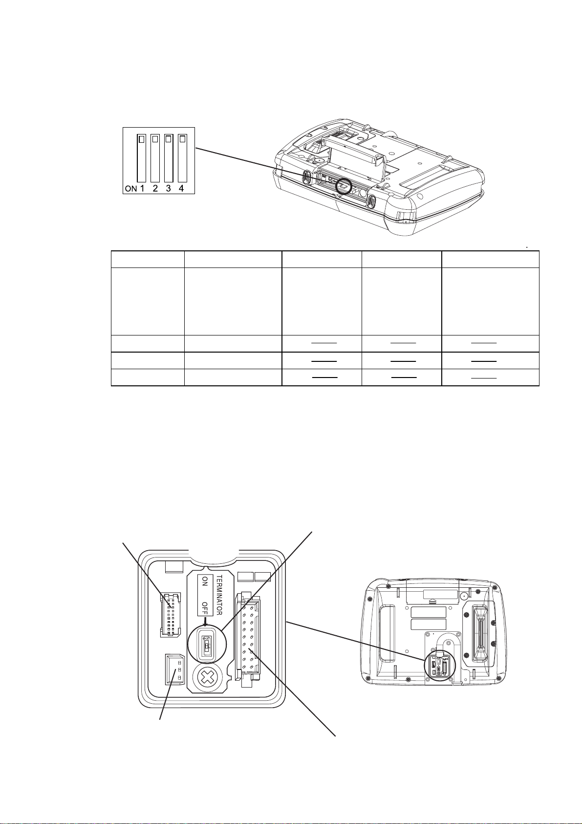
CF Card Access Switches
3Dip Switches
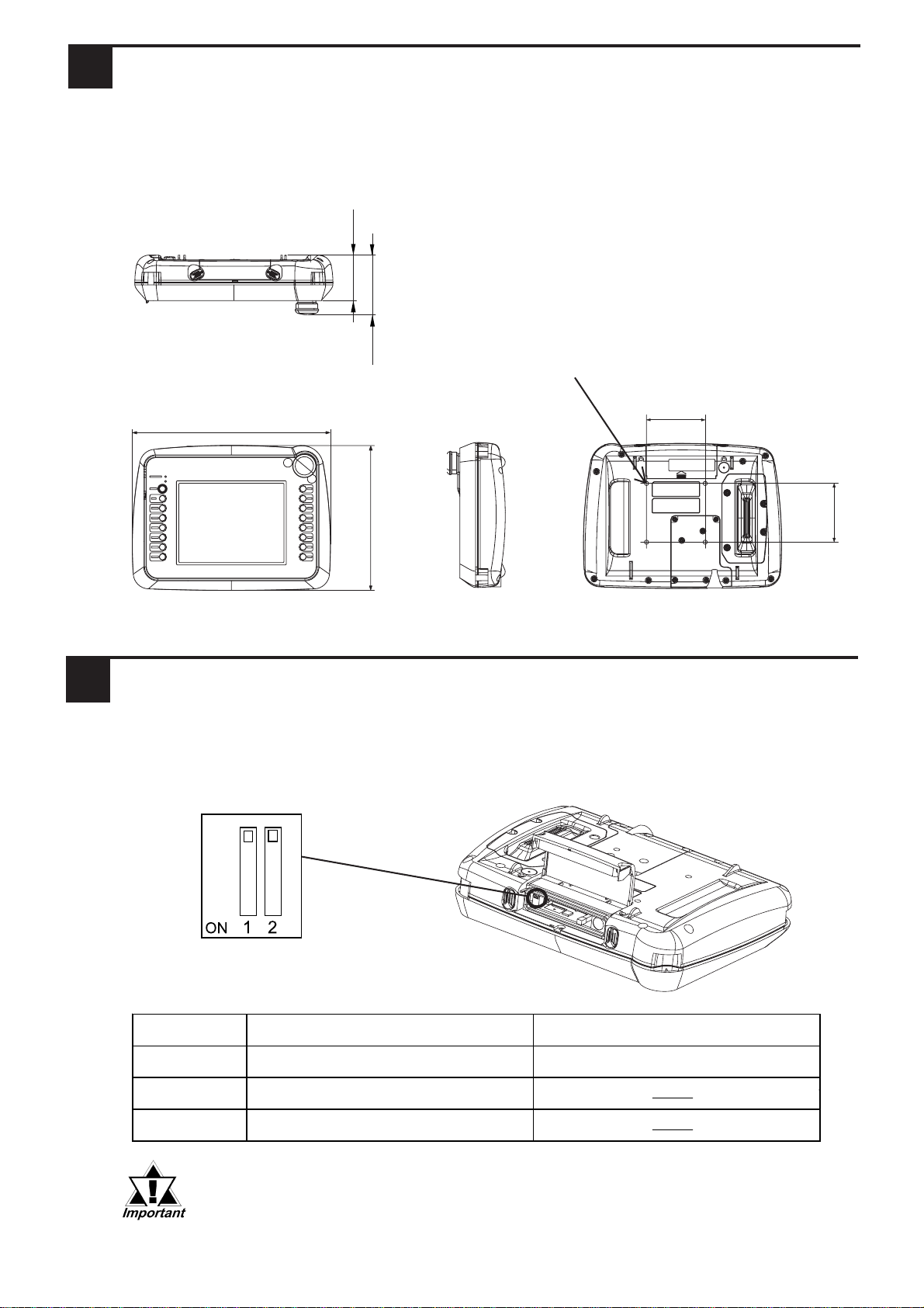
Unit:mm [in.]
2Dimensions
Even though only the GP2401H-TC41-24V is shown below, the dimensions of the
GP2301H-LG41-24V and the GP2301H-SC41-24V are the same.
Side
Top
Front
58 [2.28]
185 [7.28] 76 [2.99]
253 [9.96]
DIP SWITCH 1 2
Description Controls CF Card access Reserved
ON Allows CF Card access
OFF Does not allow CF Card access
Dip Switches
(Factory Settings)
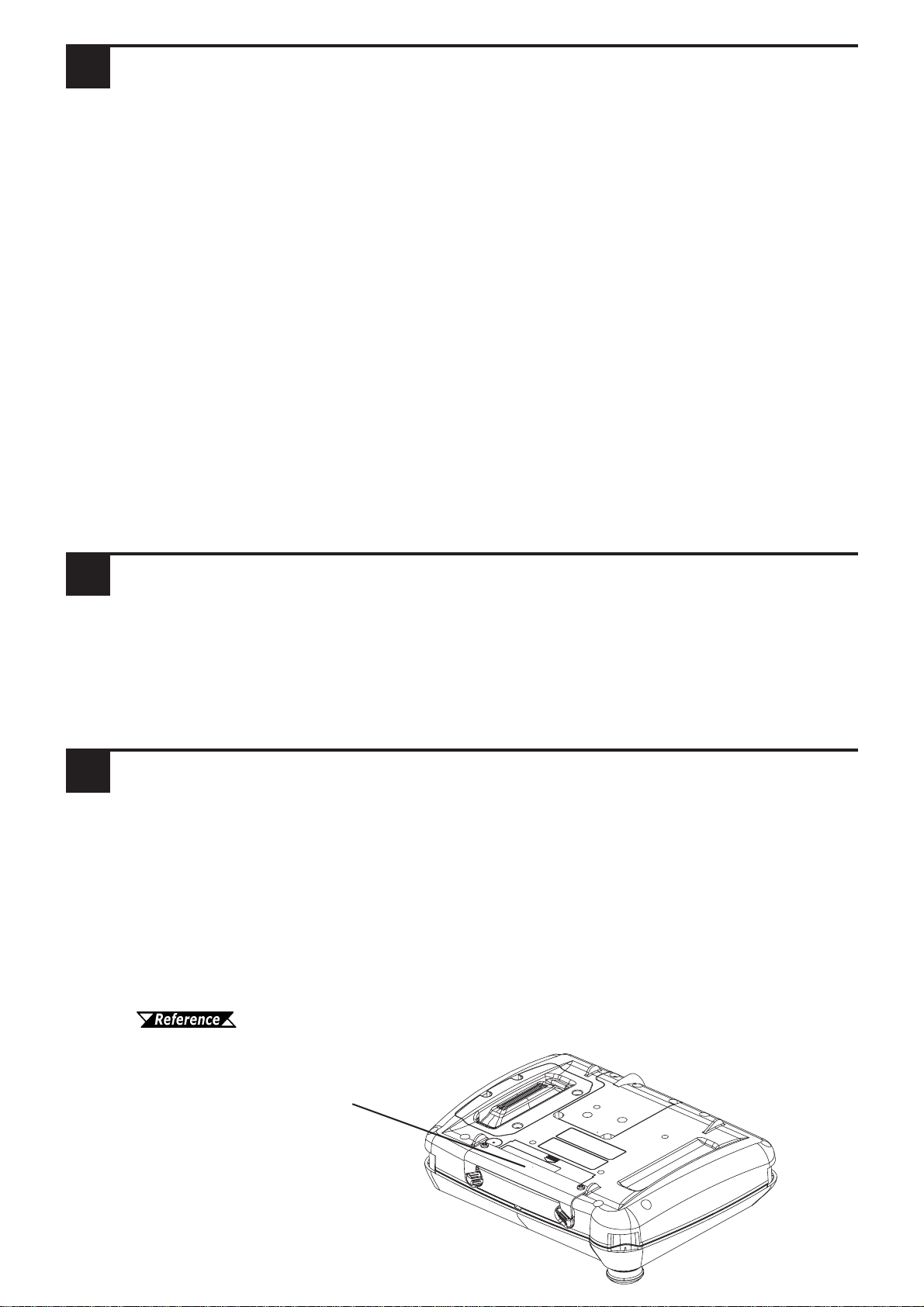
Before removing the CF Card, confirm that the CF Card Ac-
cess Switch is turned OFF and the CF Card Access LED is
not lit. If the switch is ON or the LED is lit, removal of the CF
Card may result in data loss.
The CF Card Access Switches are located inside the rear face CF Card Cover, on
the left side of the CF Card insertion slot.
Rear
75[2.95]
75
[2.95]
4-M4 Depth:8
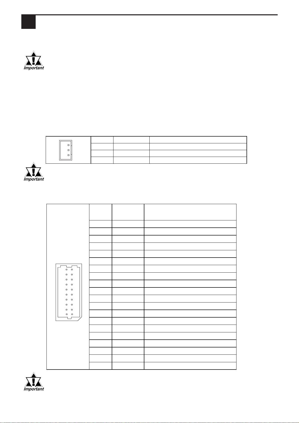
Dip Switch Description ON OFF Note
1
This Dip switch
setting controls the
startup from a CF
Card.
Startup from CF
Card is enabled. Startup from CF
Card is
disabled.
CF Card with startup
data required.
2Reserved
3Reserved
4Reserved
Dip Switches
(Factory Settings)
CF Card Startup Switches
The CF Card Startup Switches are located inside the rear face CF Card Cover, just
below the CF Card insertion slot.
Termination Resistance Switch
When you need to set the GP unit's termination resistance, this dip switch is used. It is
located next to the External Output Interface Connector. Setting it to ON will insert
100Ωof resistance. The factory setting is OFF.
DC24V I/F Connector
Serial I/F Connector
External Output I/F Connector
Termination Resistance Switch
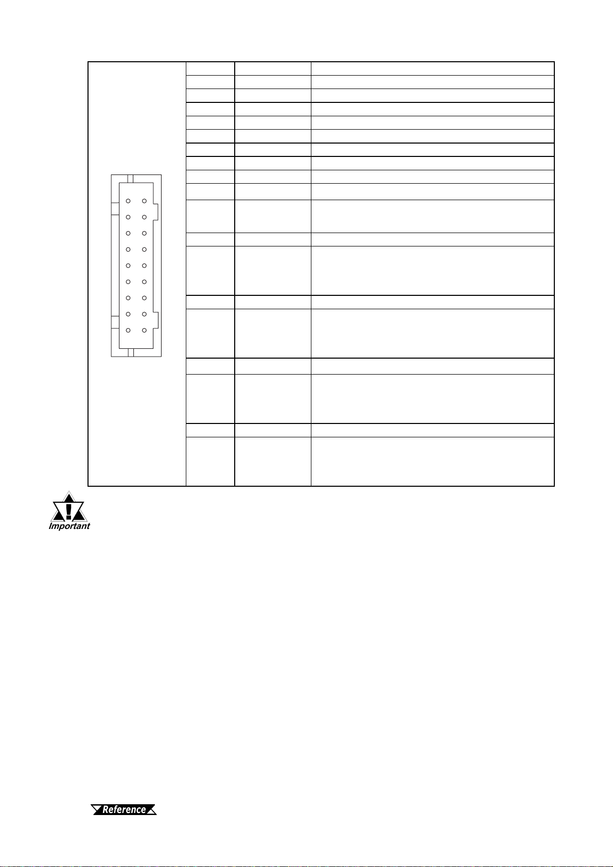
Pin # Signal Name Meaning
1 DC24V Power input+24V
2 0V Power input 0V
3 FG Frame ground
Pin # Signal
Name Condition
1 RS Requestto Send(RS-232C)
2 SD Send Data(RS-232C)
3 CS Clearto Send(RS-232C)
4 RD Receive Data (RS-232C)
5 CD CarrierDetect(RS-232C)
6 ER EnableReceive (RS-232C)
7 VCC 5V±5%Output0.25A
8 SG SignalGround
9 NC NoConnection(Reserved)
10 NC NoConnection(Reserved)
11 NC NoConnection(Reserved)
12 NC NoConnection(Reserved)
13 RDA Receive Data A(RS-422)
14 RDB Receive Data B(RS-422)
15 SDA Send Data A(RS-422)
16 SDB Send Data B(RS-422)
17 CSA CleartoSendA(RS-422)
18 CSB CleartoSendB(RS-422)
19 ERA Enable ReceiveA(RS-422)
20 ERB Enable ReceiveB(RS-422)
When connecting the FG terminal, the unit will be more suscep-
tible to noise. Be sure to earth (ground) the unit.
DC24V I/F
This interface is for DC24V input.
• Since Pin#7's (VCC) DC5V output is unprotected, be sure to
keep the output current within the rated range.
• This unit's serial port is not isolated, therefore, it is important
that you connect the SG (#8) terminals. If this is not done, the
RS422 circuit may be damaged.
This interface is used to connect the GP to the host (PLC), via an RS-232C or RS-
422 cable. The connector is located inside the Cable Cover, on the circuit board.
4External Interfaces
• When connecting the GP2000H to an external device, be sure to use a
Digital Electronic Corporation GP2000H Option Cable.
• When attaching the optional Cable Cover, to ensure a water-resistant
seal, be sure to tighten all attachment screws to 0.5N•m.
• The SG and FG terminals are connected internally in the GP unit.
• When connecting the SG line to another device, be sure that the de-
sign of the system/connection does not produce a shorting loop.
Serial I/F
This RS-232C/RS-422 interface is used to connect the GP2000H with a Host unit.
20
2
19
1
1
2
3
Pin # Signal Name Meaning
1 NC No Connection(Reserved)
2 DOUT0.C DOUT0 outputOpen Collector DC24V 300mA
3 NC No Connection(Reserved)
4 DOUT1.C DOUT1 outputOpen Collector DC24V 300mA
5 OP.GND OP. Ground
6 OP.C OP. OutputOpen Collector DC24V 300mA
7 DOUT.GND DOUT Ground
8 BUZZ OUT External buzzer output
9 EMG0B Emergency switch 0B (Operates like A contact)
10 EMG0A Emergency switch 0A (Operates like A contact)
Open Collector DC24V 300mA
11 EMG1B Emergency switch 1B (B contact)
12 EMG1A Emergency switch 1A (B contact)
Rated DC30V 1A (min. applicable load DC5V
1mA)
13 EMG2B Emergency switch 2B (B contact)
14 EMG2A Emergency switch 2A (B contact)
Rated DC30V 1A (min. applicable load DC5V
1mA)
15 ENB0B 3-Position Enable switch 0B(A contact)
16 ENB0A 3-Position Enable switch 0A (A contact)
Rated DC24V 300mA (min. applicable load
DC24V 4mA)
17 ENB1B 3-Position Enable switch 1B(A contact)
18 ENB1A 3-Position Enable switch 1A (A contact)
Rated DC24V 300mA (min. applicable load
DC24V 4mA)
External Output I/F
• #7 (DOUT.GND) is common for #2 (DOUT0.C), #4 (DOUT1.C),
and #8 (BUZZ OUT).
• When using GP-H70 compatible mode, #17 (ENB1B) and #18
(ENB1A) cannot be used.
CF Card Interface
This slot accepts a CF Card.
3-Position Enable Switch Interface
This switch/interface changes between GP2000H and GP-H70 compatible modes.
GP-H70 Compatible Mode:
This allows the 3-Position Enable switch on the rear face of the unit to be used as an
Operation switch.
When the GP2000H unit's OFFLINE mode is used to set the "Operation" feature to
"enable", this switch must be kept pressed in order to use the front face touch panel
and function switches.
For information about how to set this feature, see the "GP2000H
Series User Manual".
21
18 17
This unit can be attached to a wall or to a commercially available type of arm, if the
optional Wall Mount Adaptor is used. This adaptor can be used as follows.
When Attaching the GP2000H to a Wall
5About the GP2000H Unit
This unit can be attached to a wall, after the Wall Mount Adaptor is attached.
When Attaching the GP2000H to an Arm
This unit can be attached to a commercial type, VESA FPMPMI approved (75mm)
arm, either fixed or wall-mounted.
• VESA: Video Electronics Standard Association
• FPMPMI: Flat Panel Monitor Physical Mounting Interface (physical specification
designed by VESA for attachment of a display to either an arm or
stand.)
7CF Card Interface Guard
CF Card Interface Guard
When the GP unit's CF Card Interface Guard is attached to the GP unit, the GP
meets NEMA#250 TYPE4X/12 environment requirements.
(Even if the CF Card Interface Guard is not attached, if the CF Card Cover is
closed, the unit's protection level is maintained.)
For guard attachment details, refer to
GP2000H Series User Manual
CF Card Interface Guard
6DOUT/BUZZ Ouput Current Direction Change
To change the direction of the current from the GP unit's DOUT/BUZZ output (to
Output Source Type), refer to the GP2000H Series User Manual .
Factory settings are for Output Sink Type.

When connecting the GP2000H Series units to a Serial I/F, DC24V I/F, or External
I/F, be sure to use the Digital Electronics Corporation's GP2000H Series option
cables.
9Wiring
•To avoid an electric shock, prior to connecting the GP's power cord
terminals to the power terminal block, confirm that the GP's power
supply is completely turned OFF, via a breaker, or similar unit.
•The GP2000H Series units are designed to use only DC24V input.
Any other power level can damage both the GP and the power
supply.
•Since there is no power switch on the GP unit, be sure to attach a
breaker-type switch to its power cord.
WARNINGS
Digital's option cables are as follows.
Cable Name Model Number
RS-232C DSUB Connector 3m Cable GP2000H-D232-3M
RS-232C DSUB Connector 10m Cable GP2000H-D232-10M
RS-232C 3m Cable GP2000H-C232-3M
RS-232C 10m Cable GP2000H-C232-10M
RS-422 DSUB Connector 3m Cable GP2000H-D422-3M
RS-422 DSUB Connector 10m Cable GP2000H-D422-10M
RS-422 3m Cable GP2000H-C422-3M
RS-422 10m Cable GP2000H-C422-10M
8Emergency Switch Guard
Emergency Switch Guard
Emergency Switch Guard
This guard is used to prevent the accidental pressing of the Emergency Stop Switch
when the GP2000H unit is placed face down on a table, or is accidentally dropped.
This unit is factory equipped with two (2) Emergency Switch Guard Hole Covers
(Seals).
For guard attachment details, refer to
GP2000H Series User Manual

• When attaching a wire to the GP's rear face FG terminal, (on the Power Input
Terminal Block), be sure to create an exclusive ground.*1
• Inside the GP2301H-LG41-24V/GP2301H-SC41-24V/GP2401H-TC41-24V unit,
the SG(Signal Ground) and FG(Frame Ground) terminals are connected.
• When connecting the SG line to another device, be sure that the design of the
system/connection does not produce a shorting loop.
Please pay special attention to the following instructions when connecting the power
cord terminals to the GP unit.
•Between the line and the ground, be sure to use a low noise power supply.
•Input and Output signal lines must be separated from the power control cables
for operational circuits.
•To increase the noise resistance, be sure to twist the ends of the power cord
wires before connecting it to the GP unit.
•Connect a surge absorber to handle power surges.
•To reduce noise, make the power cord as short as possible.
*1 Use a grounding resistance of 100
Ω
, a wire of 2mm2or thicker, or your country's applicable
standard.
•All GP Input and Output signal lines must be separated from all operating circuit
(power) cables.
•If this is not possible, use a shielded cable and ground the shield.
13 Backlight Replacment
12 Input/Output Signal Line Cautions
11 Grounding Cautions
10 Power Supply Cautions
GP2000H unit backlights cannot be changed by the User. When a backlight must
be changed, please contact your local GP distributor.
Cable Name Model Number
RS-232C DSUB connector 3mCable GP2000H-AP70CB-D232-3M
RS-422 DSUB connector 3m Cable GP2000H-AP70CB-D422-3M
The following cables are used when using a GP-H70 Series Terminal Block Conver-
sion Adaptor. (GPH70-AP232-O/GPH70-AP422-O)
For unit connection information:
GP2000H Series User Manual
For Device/PLC connection information:
Device/PLC Connection Manual
This manual suits for next models
2
Table of contents
Other Pro-face Touch Terminal manuals

Pro-face
Pro-face GLC2300-LG41-24V User manual

Pro-face
Pro-face ST-3400 Series User manual

Pro-face
Pro-face AST-3501T User manual

Pro-face
Pro-face GP2500-TC41-24V User manual

Pro-face
Pro-face FP2500-T42-24V User manual

Pro-face
Pro-face GP2501-TC41-24V User manual

Pro-face
Pro-face HTB User manual

Pro-face
Pro-face GP2501-LG41-24V User manual

Pro-face
Pro-face GLC100-LG41-24V User manual


