manuals.online logo
Brands
  1. Home
  2. •
  3. Brands
  4. •
  5. Festo
  6. •
  7. Touch Terminal
  8. •
  9. Festo MPAC-V User manual

Festo MPAC-V User manual

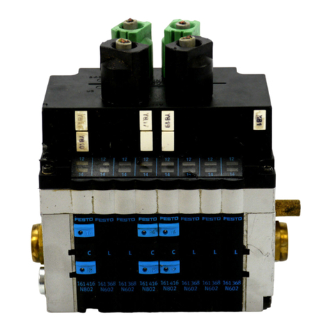
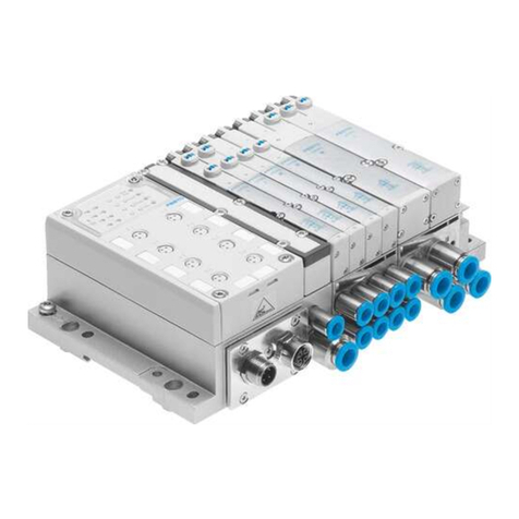
Valve terminal MPAC-VI
with I-Port/IO-Link interface
Festo AG & Co. KG
Ruiter Straße 82
73734 Esslingen
Germany
+49 711 347-0
www.festo.com
Brief description
(Original instructions)
8073671
2017-07a
[8073673]
Valve terminal MPAC-VI with I-Port/IO-Link interface English.................
IO-Link® is a registered trademark of the trademark holder in certain countries.
1 About this document
This document describes the I-Port/IO-Link interface of the valve terminal.
Additional aspects of use are described in other documents and must be observed
è1.1 Further applicable documents.
1.1 Further applicable documents
Document Table of contents
Description MPAC-VI Detailed description of installation, commis
sioning, maintenance and conversion of the
valve terminal
Description/brief description/operating in
structions CTEU-...
Detailed description of the bus node, which can
be connected in a decentralised way to the
valve terminal
Assembly instructions MPA-C Mounting methods of the valve terminal
Additional assembly instructions Mounting of valve terminal components
Fig. 1
For all available product documentation èwww.festo.com/pk
2 Safety
2.1 General safety information
Warning
Danger of injury through uncontrolled movements of connected devices. Make
sure that electrical and pneumatic equipment are in a de-energised and pressure
less status.
Before working on the pneumatics:
 Switch off the compressed air supply
 Exhaust the valve terminal
Before working on the electrical components, e.g. before installation or mainten
ance work:
 Switch power supply off
In this way, you avoid:
– sudden uncontrolled movements of loose tubing
– accidental and uncontrolled movements of the connected actuators
– undefined switching statuses of the electronics.
– functional damage.
Note
– Installation and commissioning must be carried out only by authorized quali
fied personnel.
– The components of the valve terminal include electrostatically sensitive ele
ments. The components could be damaged if you touch the contact surfaces
of the plug connectors or if you do not observe the handling specifications for
electrostatically sensitive devices.
 Do not exceed the specified limits in the technical data.
 Start up only a completely mounted and wired valve terminal in order to avoid
uncontrolled movements of detached tubing lines (whip effect) or impair
ments caused by unlocked pneumatic connections.
2.2 Use for intended purpose
The valve terminal has been designed exclusively for controlling pneumatic actuat
ors. It is intended for installation in machines or automation technology systems
and must be used exclusively as follows:
– in an industrial environment; outside of industrial environments, e.g. in commer
cial and mixed-residential areas, actions to suppress interference may have to
be taken.
– within the limits of the technical data,
– in the original status, without unauthorised modifications,
– in excellent technical status.
Use for intended purpose is described completely in the documentation. Every
other use is considered not intended.
2.3 Training of specialized personnel
The product may be commissioned only by an electrotechnically qualified person,
who is familiar with the following topics:
– installation and operation of control and automation systems
– applicable regulations for operating safety-engineering systems
– applicable regulations for accident prevention and occupational safety
– documentation for the product
3 Further information
– accessories èwww.festo.com/catalogue
– spare parts èwww.festo.com/spareparts
4 Service
Contact the regional Festo contact if you have technical questions
èwww.festo.com.
5 Product design
5.1 Display and control elements
There is an LED and a manual override (MO) for each solenoid coil. The LED and MO
for the corresponding solenoid coil are arrayed as follows:
1
2
2
1
1LED and manual override for valve
solenoid coil 14
2LED and manual override for solen
oid coil 12
Fig. 2
5.2 Power supply
Note
 Only use PELV circuits in accordance with IEC/EN 60204-1 for the electrical
power supply (protective extra-low voltage, PELV).
 Observe also the general requirements for PELV power circuits in accordance
with IEC/EN 60204-1.
 Only use voltage sources which ensure reliable electrical isolation of the oper
ating voltage in accordance with IEC/EN 60204-1.
 Always connect both circuits for operating and load voltage supply.
Through the use of PELV circuits, protection against electric shock (protection
against direct and indirect contact) is ensured in accordance with IEC/EN 60204-1.
5.3 Connecting cable
Note
– Long electric connecting cables reduce the resistance to interference. Use
connecting cables with a length of max. 30 m.
 Use the connecting cables NEBC-C-S1WA9-F-... for the valve terminal from the
Festo accessories. In this way, you ensure that protection class IP69k is ful
filled.
5.4 I-Port/IO-Link interface
The valve terminal can be connected as follows via the connecting cable:
– to an external I-Port interface
– to an IO-Link master (èChap. 7.1)
– to a decentralised CTEU bus node
Depending on the configuration of your valve terminal, the I-Port/IO-Link interface
(èFig. 3) is on the valve side (front side) or the connection side (reverse side) of
the left end plate.
Sub-D plug connector1), 9-pin Pin2) Allocation Function
1 C/Q Data communication
20 VVAL/OUT (PL) Load voltage supply
30 VEL/SEN (PS) Operating voltage supply
424 VVAL/OUT (PL) Load voltage supply
524 VEL/SEN (PS) Operating voltage supply
1) On the valve terminal
2) Pin 6 … 9 not allocated
Fig. 3
6 Addressing
Note
– Addresses may be shifted if the valve terminal is extended.
– If a monostable 5/2-way valve (requiring an address) is mounted on a valve
position that supports the actuation of 2 addresses, one address remains
unused.
6.1 Addressing rules:
– Address assignment is in ascending order without gaps, from left to right.
– Address assignment is independent of whether the manifold sub-base is
equipped with a valve or a cover plate.
– Depending on the integrated electronics module, a valve position, comprising a
manifold sub-base with electronics module, occupies the following number of
addresses:
Colour of the electronics module Number of occupied addresses/valve position
Grey 1
Black 2 – Less significant address for coils 14
– Higher-value address for coils 12
Fig. 4
– A supply plate does not occupy an address (blue electronics module).
6.2 Addressing example
The following example shows the address allocation of the valve terminal with
8 valve positions (top view).
1
2
0
35
4
7
68
10
11
9
12
4
3
1
2
5
66 7
1Less significant addresses of coils 14
2Higher-value addresses of coils 12
3Supply plate with blue electronics
module
4Manifold sub-bases with grey elec
tronics module and valve
5Manifold sub-base with black elec
tronics module, without valve
6Manifold sub-bases with black
electronics modules and valves
7Manifold sub-base with black elec
tronics module, valve and addi
tional supply
Fig. 5
7 Installation and commissioning
Installation and commissioning of the pneumatics as well as maintenance
and modification of the valve terminal can be found in the description
MPAC-VI-...
7.1 IO-Link mode
The valve terminal can also be operated as an IO-Link device. The IODD configura
tion file required for this can be downloaded at èwww.festo.com/sp.
7.2 Malfunction and error handling
Malfunctions and statuses are transmitted in the form of event codes to the master.
Event code Malfunction and error handling Type
MSB LSB
50h 00h Device errors
 Switch device off and back on. If the error is still present,
the device is defective and needs to be replaced.
Error
51h 12h Error in the load voltage supply
 Check the load voltage supply
Warning
Fig. 6
8 Technical data
Valve terminal with I-Port/IO-Link interface:
General technical data èDescription MPAC-VI-...
Ambient temperature [°C] -5 … +60
Storage temperature [°C] -20 … +40
Maximum number of valve posi
tions
32
Maximum number of controllable coils 32
Degree of protection1) IP65/IP67 in accordance with IEC/EN 60529
IP69k in accordance with DIN 40050 part 9
NEMA6 in accordance with NEMA 250
Protection against electric shock, protec
tion against direct and indirect contact in
accordance with IEC/EN 60204-1
By means of PELV power circuit
Power supply valve terminal4)
– Operating voltage (PS), polar
ity-safe nominal value (toler
ance range)
[V DC]
24 (18 … 30)
– Load voltage (PL) nominal
value (tolerance range)
[V DC]
24 (18 … 30)
Valve terminal intrinsic current consumption at 24 V DC
– Operating voltage supply
UEL/SEN (PS)
[mA] 30
– Load voltage supply
UVAL/OUT (PL)
[mA] 30
Current consumption (per coil, with LED) at 24 V DC
– Nominal pick-up current [mA] 50
– Pick-up duration [ms] 25
– Nominal current with current
reduction (holding current)
[mA] 10
Mains buffering time
(only operating voltage (PS))
[ms] 10
I-Port/IO-Link connecting cable
– Wire cross section, at least [mm²] 0.5
– Max. length, unshielded [m] 20
IO-Link characteristics
– Operating mode (data transfer rate) COM 3 (230.4 kBaud)
COM 2 (38.4 kBaud)
– Specification Revision 1.1 (backwards compatible)
– Data out 4 bytes (1 … 32 valves)
Electromagnetic compatibility (Emitted in
terference2), resistance to interference3))èDeclaration of conformity (www.festo.com)
Tightening torque
– Electrical connecting cable [Nm] 0.5 ± 10 %
1) Requirement: valve terminal completely mounted, plug connector inserted. Observe that connected
devices might only satisfy a lower degree of protection, a smaller temperature range, etc.
2) The valve terminal is intended for use in an industrial environment. Measures for interference suppres
sion may need to be implemented in residential areas.
3) Use connecting cables with a length of maximum 30 m.
4) The operating voltage supply is provided via the CTEU bus node or IO-Link master. The load voltage
supply is through the CTEU bus node or, for IO-Link, through a separate feed. Separate fuses are re
quired for operating and load voltage.
Fig. 7
Other Festo Touch Terminal manuals

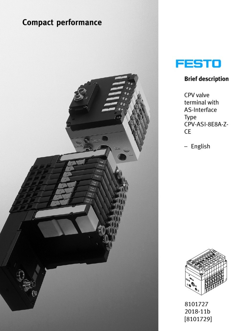
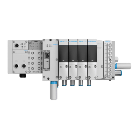
Festo CPV GEASI-4E4A Series Parts list manual

Festo

Festo CPV GEASI-4E4A Series Parts list manual

Festo CPV ASI-4E3A-Z Series Parts list manual

Festo

Festo CPV ASI-4E3A-Z Series Parts list manual

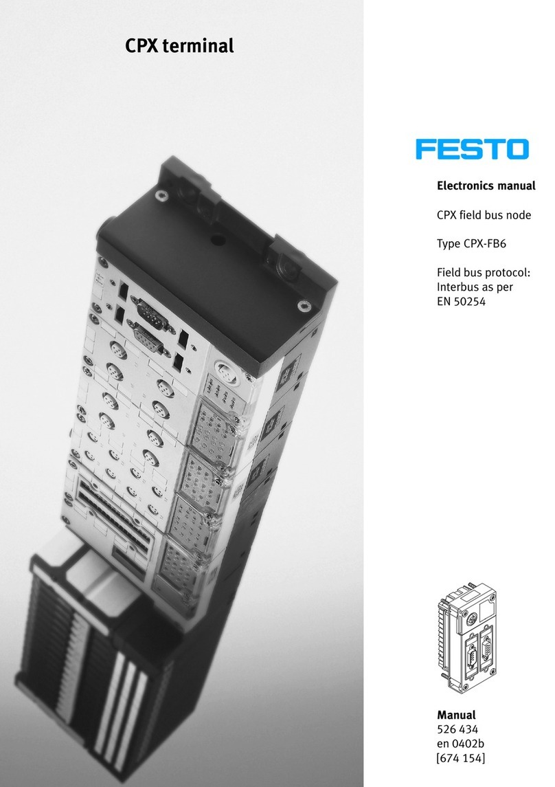
Festo CPX Series User manual

Festo

Festo CPX Series User manual

Festo CPX Series User manual

Festo

Festo CPX Series User manual

Festo CDVI Series User manual

Festo

Festo CDVI Series User manual

Festo CPX-FB14 User manual

Festo

Festo CPX-FB14 User manual

Festo CPX-FB37 User manual

Festo

Festo CPX-FB37 User manual

Festo CPX-FB13 User manual

Festo

Festo CPX-FB13 User manual

Festo VIFB11-02 Series User manual

Festo

Festo VIFB11-02 Series User manual

Festo CPX-CM-HPP User manual

Festo

Festo CPX-CM-HPP User manual

Festo CPX-M-FB20 User manual

Festo

Festo CPX-M-FB20 User manual

Festo CPV-GE-DN3-8 Series User manual

Festo

Festo CPV-GE-DN3-8 Series User manual

Festo CPV GE-ASI-8E8A-Z M8 Series Parts list manual

Festo

Festo CPV GE-ASI-8E8A-Z M8 Series Parts list manual

Festo VTOP User manual

Festo

Festo VTOP User manual

Festo CPX-FB13 User manual

Festo

Festo CPX-FB13 User manual

Festo CPV GE-ASI-8E6A-Z Series Parts list manual

Festo

Festo CPV GE-ASI-8E6A-Z Series Parts list manual

Festo CPX User guide

Festo

Festo CPX User guide

Festo VTEM Parts list manual

Festo

Festo VTEM Parts list manual

Festo CPV GE-ASI-4E3A-Z Series Parts list manual

Festo

Festo CPV GE-ASI-4E3A-Z Series Parts list manual

Festo CPV -VI Series User manual

Festo

Festo CPV -VI Series User manual

Festo CPX-P User manual

Festo

Festo CPX-P User manual

Festo CPV Series Parts list manual

Festo

Festo CPV Series Parts list manual

Festo NAW VDMA-02 Series Parts list manual

Festo

Festo NAW VDMA-02 Series Parts list manual

Festo CPX-FB33 User manual

Festo

Festo CPX-FB33 User manual

Popular Touch Terminal manuals by other brands

ZKTeco LockerPad-7B user manual

ZKTeco

ZKTeco LockerPad-7B user manual

First Data VeriFone VX 680 Quick setup guide

First Data

First Data VeriFone VX 680 Quick setup guide

Infinite Peripherals Infinea mPOS Plus user manual

Infinite Peripherals

Infinite Peripherals Infinea mPOS Plus user manual

Partner PT-9000 user manual

Partner

Partner PT-9000 user manual

AML M7220 quick start guide

AML

AML M7220 quick start guide

Digital Electronics Corporation Pro-face GLC2300 user manual

Digital Electronics Corporation

Digital Electronics Corporation Pro-face GLC2300 user manual

Toshiba ST-71 SERIES owner's manual

Toshiba

Toshiba ST-71 SERIES owner's manual

Newland NL-8510 POS user manual

Newland

Newland NL-8510 POS user manual

EMS Ingenico Desk/5000 manual

EMS

EMS Ingenico Desk/5000 manual

Poindus VariPOS 715S user manual

Poindus

Poindus VariPOS 715S user manual

Symbol PDT 7500 Series manual

Symbol

Symbol PDT 7500 Series manual

Bosch Rexroth IndraControl VCP 35.2 Project planning manual

Bosch

Bosch Rexroth IndraControl VCP 35.2 Project planning manual

Pidion BIP-5000 manual

Pidion

Pidion BIP-5000 manual

GAI-Tronics 9974 manual

GAI-Tronics

GAI-Tronics 9974 manual

Rockwell Automation Allen-Bradley PanelView 800 HMI installation instructions

Rockwell Automation

Rockwell Automation Allen-Bradley PanelView 800 HMI installation instructions

Feig Electronic ID MAX50.10-E Installation

Feig Electronic

Feig Electronic ID MAX50.10-E Installation

Hytera TETRA owner's manual

Hytera

Hytera TETRA owner's manual

FlexKom POS 4S Installation

FlexKom

FlexKom POS 4S Installation

manuals.online logo
manuals.online logoBrands
  • About & Mission
  • Contact us
  • Privacy Policy
  • Terms and Conditions

Copyright 2025 Manuals.Online. All Rights Reserved.