manuals.online logo
Brands
  1. Home
  2. •
  3. Brands
  4. •
  5. Pro-Form
  6. •
  7. Exercise Bike
  8. •
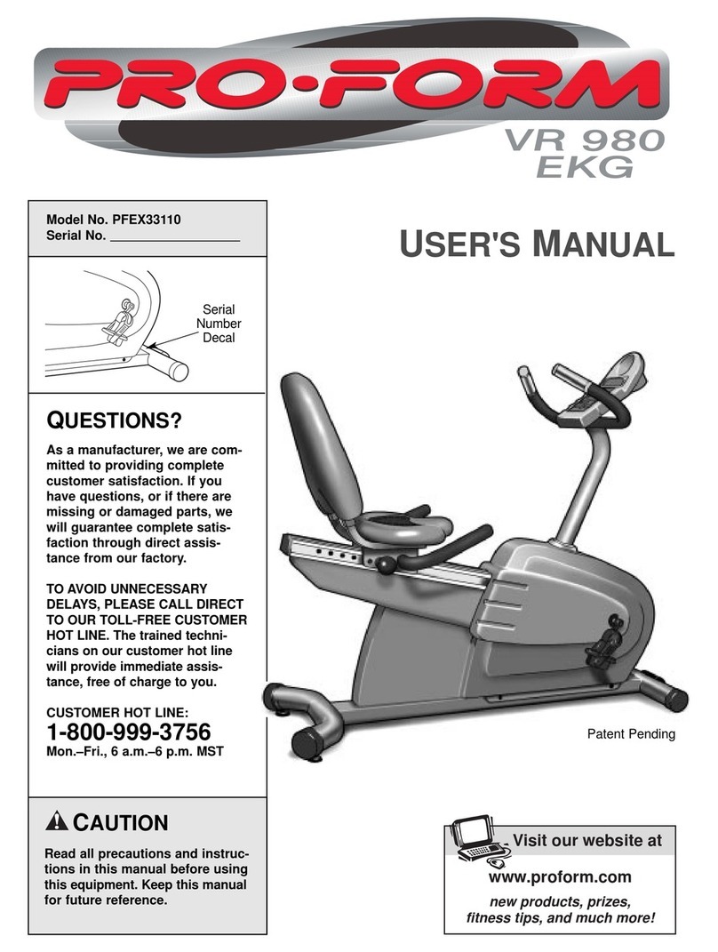
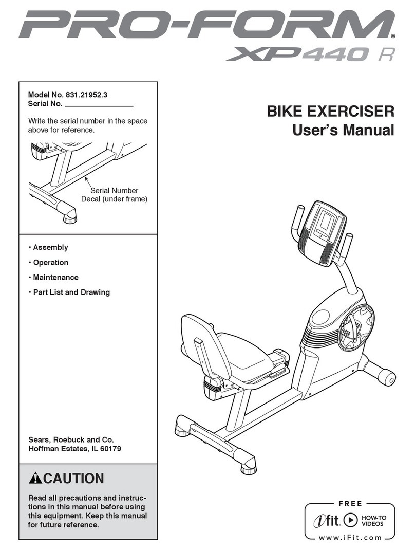
  9. Pro-Form PFCCEX34390 User manual

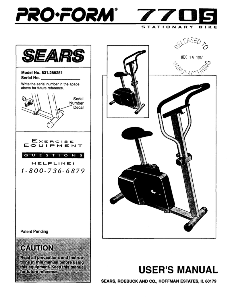
Pro-Form PFCCEX34390 User manual

This manual suits for next models

1

Other Pro-Form Exercise Bike manuals

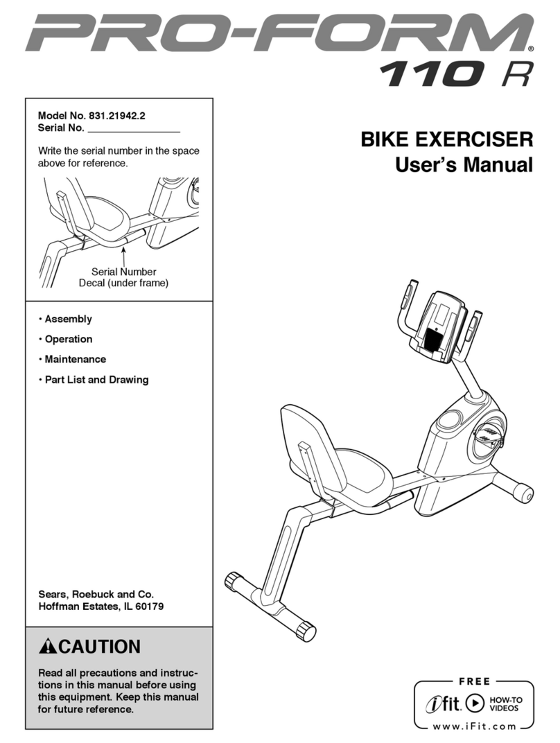
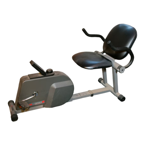
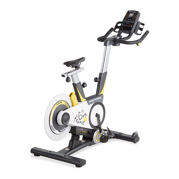
Pro-Form PFEVEX79911.0 User manual

Pro-Form

Pro-Form PFEVEX79911.0 User manual

Pro-Form 1550cwi User manual

Pro-Form

Pro-Form 1550cwi User manual

Pro-Form 740 Ekg Bike System manual

Pro-Form

Pro-Form 740 Ekg Bike System manual

Pro-Form 290 Csr Bike User manual

Pro-Form

Pro-Form 290 Csr Bike User manual

Pro-Form 120 R User manual

Pro-Form

Pro-Form 120 R User manual

Pro-Form 748 Ekg Bike Operating and maintenance manual

Pro-Form

Pro-Form 748 Ekg Bike Operating and maintenance manual

Pro-Form Carbon CX User manual

Pro-Form

Pro-Form Carbon CX User manual

Pro-Form 831.280441 User manual

Pro-Form

Pro-Form 831.280441 User manual

Pro-Form PFEX02210.0 User manual

Pro-Form

Pro-Form PFEX02210.0 User manual

Pro-Form 100 Zlx Bike Operating and maintenance manual

Pro-Form

Pro-Form 100 Zlx Bike Operating and maintenance manual

Pro-Form PFEX6976.0 GT 120 User manual

Pro-Form

Pro-Form PFEX6976.0 GT 120 User manual

Pro-Form c740 User manual

Pro-Form

Pro-Form c740 User manual

Pro-Form 740 Ekg Bike Quick start guide

Pro-Form

Pro-Form 740 Ekg Bike Quick start guide

Pro-Form PFEX16718.5 User manual

Pro-Form

Pro-Form PFEX16718.5 User manual

Pro-Form 385 Csx Bike User manual

Pro-Form

Pro-Form 385 Csx Bike User manual

Pro-Form 831.288221 User manual

Pro-Form

Pro-Form 831.288221 User manual

Pro-Form 750 Ekg Bike User manual

Pro-Form

Pro-Form 750 Ekg Bike User manual

Pro-Form 748 Ekg Bike Quick start guide

Pro-Form

Pro-Form 748 Ekg Bike Quick start guide

Pro-Form 350 CSX User manual

Pro-Form

Pro-Form 350 CSX User manual

Pro-Form 425 Zlx Bike User manual

Pro-Form

Pro-Form 425 Zlx Bike User manual

Pro-Form PFEX25122 User manual

Pro-Form

Pro-Form PFEX25122 User manual

Pro-Form 280 Zlx Bike Setup guide

Pro-Form

Pro-Form 280 Zlx Bike Setup guide

Pro-Form 455 Ekg Bike User manual

Pro-Form

Pro-Form 455 Ekg Bike User manual

Pro-Form PFEX31420 User manual

Pro-Form

Pro-Form PFEX31420 User manual

Popular Exercise Bike manuals by other brands

BH BLADEZ 200U owner's manual

BH

BH BLADEZ 200U owner's manual

Eco-De ECO-800 Instruction guide

Eco-De

Eco-De ECO-800 Instruction guide

Nautilus Be Strong Commercial Series U916 owner's manual

Nautilus

Nautilus Be Strong Commercial Series U916 owner's manual

NordicTrack Gx 3.1 Bike Manual Del Usuario

NordicTrack

NordicTrack Gx 3.1 Bike Manual Del Usuario

NordicTrack Gx 3.1 Bike Instrukcja obsŁugi

NordicTrack

NordicTrack Gx 3.1 Bike Instrukcja obsŁugi

Tomahawk IC3 manual

Tomahawk

Tomahawk IC3 manual

GPI Sports & Fitness BODYWORX ABX250M manual

GPI Sports & Fitness

GPI Sports & Fitness BODYWORX ABX250M manual

Trixter X-Bike user manual

Trixter

Trixter X-Bike user manual

TOORX BRX85 Instruction

TOORX

TOORX BRX85 Instruction

Matrix KranKcycle user manual

Matrix

Matrix KranKcycle user manual

Weslo Vector 302 Bedienungsanleitung

Weslo

Weslo Vector 302 Bedienungsanleitung

Matrix IC3 manual

Matrix

Matrix IC3 manual

Sunny Health & Fitness SF-B121021 user manual

Sunny Health & Fitness

Sunny Health & Fitness SF-B121021 user manual

Monark 827E instruction manual

Monark

Monark 827E instruction manual

Stamina 1310 owner's manual

Stamina

Stamina 1310 owner's manual

American Fitness SPR-BK1072A owner's manual

American Fitness

American Fitness SPR-BK1072A owner's manual

Cateye CS-1000 (CYCLO SIMULATOR) Service manual

Cateye

Cateye CS-1000 (CYCLO SIMULATOR) Service manual

BH FITNESS H9158H Instructions for assembly and use

BH FITNESS

BH FITNESS H9158H Instructions for assembly and use

manuals.online logo
manuals.online logoBrands
  • About & Mission
  • Contact us
  • Privacy Policy
  • Terms and Conditions

Copyright 2025 Manuals.Online. All Rights Reserved.

USER'S MANUAL
CAUTION
Read all precautions and instruc-
tions in this manual be ore using
this equipment. Keep this manual
or uture re erence.
Serial
Number
Decal
QUESTIONS?
As a manu acturer, we are com-
mitted to providing complete
customer satis action. I you
have questions, or i there are
missing parts, we will guarantee
complete satis action through
direct assistance rom our actory.
TO AVOID UNNECESSARY
DELAYS, PLEASE CALL
DIRECT TO OUR TOLL-FREE
CUSTOMER HOT LINE. The
trained technicians on our
customer hot line will provide
immediate assistance, ree o
charge to you.
CUSTOMER HOT LINE:
1-888-936-4266
Mon.–Fri., 8 a.m.–6:30 p.m.
Eastern Standard Time
Model No. PFCCEX34390
Serial No.
Patent Pending
Visit our website at
www.pro orm.com
new products, prizes,
fitness tips, and much more!
2
TABLE OF CONTENTS
IMPORTANT PRECAUTIONS . . . . . . . . . . . . . . . . . . . . . . . . . . . . . . . . . . . . . . . . . . . . . . . . . . . . . . . . . . . . .3
BEFORE OU BEGIN . . . . . . . . . . . . . . . . . . . . . . . . . . . . . . . . . . . . . . . . . . . . . . . . . . . . . . . . . . . . . . . . . . .4
ASSEMBL . . . . . . . . . . . . . . . . . . . . . . . . . . . . . . . . . . . . . . . . . . . . . . . . . . . . . . . . . . . . . . . . . . . . . . . . . . .5
HOW TO OPERATE THE RECUMBENT C CLE . . . . . . . . . . . . . . . . . . . . . . . . . . . . . . . . . . . . . . . . . . . . . . .9
MAINTENANCE AND TROUBLE-SHOOTING . . . . . . . . . . . . . . . . . . . . . . . . . . . . . . . . . . . . . . . . . . . . . . . .12
CONDITIONING GUIDELINES . . . . . . . . . . . . . . . . . . . . . . . . . . . . . . . . . . . . . . . . . . . . . . . . . . . . . . . . . . . .13
CUSTOMER RECORD . . . . . . . . . . . . . . . . . . . . . . . . . . . . . . . . . . . . . . . . . . . . . . . . . . . . . . . . . . . . . . . . .14
HOW TO ORDER REPLACEMENT PARTS . . . . . . . . . . . . . . . . . . . . . . . . . . . . . . . . . . . . . . . . . . . . . . . . . .15
LIMITED WARRANT . . . . . . . . . . . . . . . . . . . . . . . . . . . . . . . . . . . . . . . . . . . . . . . . . . . . . . . . . . .Back Cover
Note: An EXPLODED DRAWING and a PART LIST are attached in the centre of this manual. Save the
EXPLODED DRAWING and PART LIST for future reference.
3
1. Read all instructions in this manual be ore
using the recumbent cycle.
2. It is the responsibility o the owner to ensure
that all users o the recumbent cycle are ade-
quately in ormed o all precautions. Use the
recumbent cycle only as described in this
manual.
3. Use the recumbent cycle indoors on a level
sur ace. Keep the recumbent cycle away rom
moisture and dust. Place a mat under the
recumbent cycle to protect the loor.
4. Inspect and tighten all parts regularly.
Replace any worn parts immediately.
5. Keep children under the age o 12 and pets
away rom the recumbent cycle at all times.
6. Wear appropriate clothing when exercising;
do not wear loose clothing that could become
caught on the recumbent cycle. Always wear
athletic shoes when using the recumbent
cycle.
7. The cycle should not be used by persons
weighing more than 250 pounds (115 kg).
8. Always keep your back straight when using
the recumbent cycle; do not arch your back.
9. I you eel pain or dizziness while exercising,
stop immediately and cool down.
10. The recumbent cycle does not have a ree-
wheel; the pedals will continue to move until
the lywheel stops.
11. The pulse sensor is not a medical device.
Various actors, including the user's move-
ment, may a ect the accuracy o heart rate
readings. The pulse sensor is intended only
as an exercise aid in determining heart rate
trends in general.
12.The recumbent cycle is intended or home
use only. Do not use the recumbent cycle in
a commercial, rental, or institutional setting.
WARNING:Be ore beginning this or any exercise program, consult your physician. This
is especially important or persons over the age o 35 or persons with pre-existing health problems.
Read all instructions be ore using. ICON assumes no responsibility or personal injury or property
damage sustained by or through the use o this product.
IMPORTANT PRECAUTIONS
WARNING:To reduce the risk o serious injury, read the ollowing important precau-
tions be ore using the recumbent cycle.
4
Congratulations for selecting the new PROFORM®
985R recumbent cycle. Cycling is one of the most
effective exercises for increasing cardiovascular fit-
ness, building endurance, and toning the entire body.
The PROFORM®985R offers an impressive array of
features to let you enjoy this healthful exercise in the
convenience and privacy of your home.
For your bene it, read this manual care ully be ore
you use the PROFORM®985R. If you have questions,
please call our Customer Service
Department toll-free at 1-888-936-4266, Monday
through Friday, 8 a.m. until 6:30 p.m. Eastern
Standard Time (excluding holidays). To help us assist
you, please mention the product model number and
serial number when calling. The model number is
PFCCEX34390. The serial number can be found on a
decal attached to the recumbent cycle (see the front
cover of this manual).
Before reading further, please familiarize yourself with
the parts that are labeled in the drawing below.
Pulse Sensor
Handlebar
FRONT
BACK
Seat
Backrest
Side Shield
Wheel
Pedal
Pedal Strap
Console
Book Holder
Seat Handle
LEFT SIDE
BEFORE YOU BEGIN
5
ASSEMBLY
Assembly requires two persons. Place all parts of the recumbent cycle in a cleared area and remove the pack-
ing materials. Do not dispose of the packing materials until assembly is completed.
Assembly requires the included tools and your own adjustable wrench and Phillips screw-
driver .
Use the part drawings below to identify the small parts used in assembly. The number in parenthesis below
each drawing refers to the key number of the part, from the PART LIST in the center of this manual. The second
number refers to the quantity needed for assembly. Note: Some small parts may have been pre-attached or
shipping. I a part is not in the parts bag, check to see i it has been pre-attached.
M6 Nylon Locknut (15)–4
M6 x 38mm Button Bolt (14)–7
M10 Nylon Locknut (45)–2
M10 X 75mm Carriage Bolt (72)–2
M10 x 25mm Button
Head Screw (74)–10
M8 Washer (20)–7
M6 Washer (22)–3
M8 x 38mm
Button Bolt (24)–4
M6 x 22mm
Button Screw (29)–4
M8 x 100mm Button Bolt (63)–3
M10 Split Washer (17)–10
M4 x 16mm
Screw (21)–6
Ground Screw (82)–1
6
1. Attach the Front Stabilizer (2) to the front of the
Frame (1) with two M10 x 75mm Carriage Bolts (72)
and two M10 Nylon Locknuts (45). Make sure that
the Front Stabilizer is turned so the Wheels (75)
are not touching the loor.
2. Slide the Carriage Bar (7) onto the indicated tube on
the Frame (1). Attach the Carriage Bar to the Frame
with four M10 x 25mm Button Screws (74) and four
M10 Split Washers (17).
If the Seat Carriage (11) is not on the Carriage Bar
(7), pivot the Seat Handle (79) to the position shown
and slide the Seat Carriage onto the Carriage Bar.
Move the Seat Carriage to the desired position and
pivot the Seat Handle forward to secure the Seat.
3. Position the Rear Stabilizer (3) under the Carriage
Bar (7) as shown. Attach the Rear Stabilizer to the
Carriage Bar with three M8 x 100mm Button Bolts
(63) and three M8 Washers (20).
2
11 79
3
7
63 63
20
17
7
17
17
17
74
74
1
20
3
2
75
1
72
45
1
7
4. Insert the lower end of the Backrest Frame (8) into
the Seat Frame (27). Attach the Seat Frame and the
Backrest Frame to the Seat Carriage (11) with four
M8 x 38mm Button Bolts (24).
5. Slide a Seat Handle (61) onto one side of the
Backrest Frame (8). Attach the Seat Handle with
two M6 x 38mm Button Bolts (14) and two M6 Nylon
Locknuts (15).
Attach the other Seat Handle (not shown) to the
other side of the Backrest Frame (8).
14
13
8
22
4
7
8
24
24
27
11
20
20
12
27
61
8
29 29
15
6
14
7. Attach the Backrest (13) to the Backrest Frame (8)
with three M6 x 38mm Button Bolts (14) and three
M6 Washers (22).
6. Attach the Seat (12) to the Seat Frame (27) with
four M6 x 22mm Button Screws (29) and four M8
Washers (20).
5
8
9
21
21 6
10
11
18
Hole
9
71
Console
Wires
Console
Ground
Wire
82
71
16
74
17
6
6
17
9
9. While another person holds the Handlebar (16) near
the Upright (6), route the two Pulse Wires (71) into
the Upright and out of the hole at the top of the
Upright.
Next, attach the Handlebar (16) to the Upright (6)
with two M10 x 25mm Button Screws (74) and two
M10 Split Washers (17). Make sure that the Pulse
Wires (71) are not pinched between the Handle-
bar and the Upright.
11. Attach the Console (9) to the Upright (6) with the
four M4 x 16mm Screws (21). Make sure that no
wires are pinched between the Console and the
Upright.
10. Hold the Console (9) near the Upright (6) as shown.
Identify the green console ground wire and attach it
to the Upright with a Ground Screw (82). Make sure
that the console ground wire connector is point-
ed toward the center o the indicated hole as
shown.
Next, connect the Extension Wire (18) and the two
Pulse Wires (71) to the corresponding wires on the
Console (9). Make sure that the wires are not tan-
gled around each other.
8. While another person holds the Upright (6) in the
position shown, connect the Extension Wire (18) to
the Wire Harness (69).
Carefully slide the Upright (6) onto the Frame (1).
Be care ul to avoid pinching the wires. Loosely
thread four M10 x 25mm Button Screws (74) with
M10 Split Washers (17) into the Upright and the
Frame. Attach the tops of the Side Shields (4, 5)
with two M4 x 16mm Screws (21).
Firmly tighten the four M10 x 25mm Button Screws
(74) in the following order: front, rear, and then sides.
6
69
45
17
17
18
74
74
Front
Rear
121
21
8
9
HOW TO ADJUST THE POSITION OF THE SEAT
For effective exer-
cise, the seat
should be in the
proper position.
As you pedal,
there should be a
slight bend in
your knees when
the pedals are in
the farthest posi-
tion. IMPOR-
TANT: A ter you
adjust the seat, make sure that your knees will not
touch the handlebar or the console when you
pedal. To adjust the seat, first pivot the seat handle to
the position shown in the drawing. Next, slide the seat
forward or back to the desired position. To secure the
seat, pivot the seat handle forward.
HOW TO ADJUST THE PEDAL STRAPS
To adjust the pedal
straps, first pull the
straps off the tabs on
the pedals. Adjust the
straps to the desired
positions and press
the straps back onto
the tabs.
Seat
Seat
Handle Strap
Tab
HOW TO OPERATE THE RECUMBENT CYCLE
40
Tab
19
41
12
86
Jack
13
14. Make sure that all parts are properly tightened be ore you use the recumbent cycle. Note: After
assembly is completed, some extra parts may be left over. Place a mat beneath the recumbent cycle to protect
the floor.
13. Plug the Power Supply (86) into the jack at the rear
of the recumbent cycle. Note: Your Power Supply
may look di erent rom the one pictured.
IMPORTANT: When unplugging the Power
Supply (86), always unplug the Power Supply
rom the recumbent cycle irst and then rom the
wall outlet.
12. Identify the Left Pedal (40) (there is an “L” on the
Left Pedal for identification). Using an adjustable
wrench, irmly tighten the Left Pedal counterclock-
wise into the left arm of the Crank (19). Tighten the
Right Pedal (not shown) clockwise into the right arm
of the Crank. Tighten both Pedals as irmly as
possible. Important: A ter using the recumbent
cycle or one week, retighten the Pedals. For best
per ormance, the Pedals must be kept properly
tightened.
Adjust the Left Pedal Strap (41) to the desired posi-
tion and press the Pedal Strap onto the tab on the
Left Pedal (40). Adjust the Right Pedal Strap (not
shown) in the same way.
10
DESCRIPTION OF THE CONSOLE
The innovative console offers a manual mode and
three preset workout programs. When the manual
mode is selected, the pedaling resistance can be
changed with a touch of a button. When a preset pro-
grams is selected, the console will automatically con-
trol the pedaling resistance to give you an effective
workout. The console also features seven monitor
modes that provide instant exercise feedback:
Speed—When a mode arrow points to this sym-
bol, the console will show your pedaling speed,
in miles per hour.
Time—When a mode arrow points to this sym-
bol, the console will show the elapsed time.
Distance—When a mode arrow points to this
symbol, the console will show the distance you
have pedaled, in miles.
Fat Calorie—When a mode arrow points to this
symbol, the console will show the approximate
number of fat calories you have burned (see Fat
Burning on page 13).
Calorie—When a mode arrow points to this sym-
bol, the console will show the approximate num-
ber of calories you have burned.
Scan—When a mode arrow points to this sym-
bol, the console will show the speed, time, dis-
tance, fat calorie, and calorie modes, for 5 sec-
onds each, in a continuous cycle.
Pulse—The pulse window will show your heart
rate when the pulse monitor is used.
HOW TO USE THE MANUAL MODE
Plug in the power supply.
Plug the power supply into the recumbent cycle
(see assembly step 13 on page 9). Next, plug the
power supply into an electrical outlet. Note:
When you plug in the power supply, press the
on/reset button, or activate the console by
turning the pedals, the resistance motor will
automatically calibrate itsel . During calibra-
tion, you will hear the resistance motor turn-
ing. Wait until calibration is complete be ore
continuing.
Turn on the power.
Press the on/reset button or simply begin pedal-
ing to turn on the power. The entire display will
appear for a moment; the console will then be
ready for use. Note: If the power supply was just
plugged in, the power will already be on.
Select the manual mode.
When the power is
turned on, the manu-
al mode will be
selected and the
manual indicator will
light. If a preset pro-
gram has been
selected, press the
select button repeat-
edly until the manual
indicator lights.
3
2
1
Resistance
Buttons Mode
Button On/Reset
Button Select
Button
Program
Profiles
Mode Arrow
Manual
Indicator