manuals.online logo
Brands
  1. Home
  2. •
  3. Brands
  4. •
  5. Pro-Form
  6. •
  7. Treadmill
  8. •
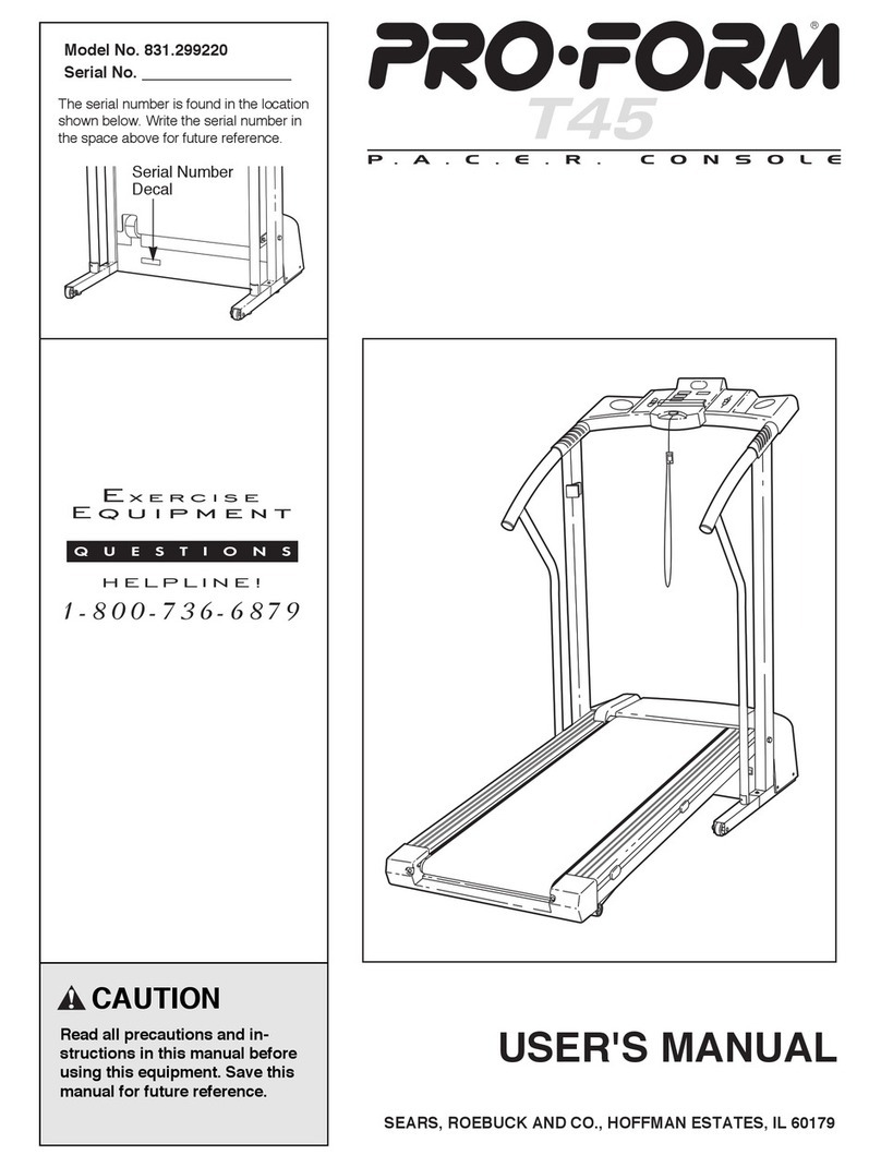
  9. Pro-Form 831.293062 User manual

Pro-Form 831.293062 User manual

This manual suits for next models

1

Other Pro-Form Treadmill manuals

Pro-Form 6.0 RT User manual

Pro-Form

Pro-Form 6.0 RT User manual

Pro-Form 730 Zlt Treadmill User manual

Pro-Form

Pro-Form 730 Zlt Treadmill User manual

Pro-Form PETL3013.5 User manual

Pro-Form

Pro-Form PETL3013.5 User manual

Pro-Form 400treadmill User manual

Pro-Form

Pro-Form 400treadmill User manual

Pro-Form 5.2 Treadmill

Pro-Form

Pro-Form 5.2 Treadmill

Pro-Form 5.0 Crosstrainer Treadmill User manual

Pro-Form

Pro-Form 5.0 Crosstrainer Treadmill User manual

Pro-Form 520 Trainer User manual

Pro-Form

Pro-Form 520 Trainer User manual

Pro-Form 8.5 Personal Fitness Trainer User manual

Pro-Form

Pro-Form 8.5 Personal Fitness Trainer User manual

Pro-Form 831.297780 User manual

Pro-Form

Pro-Form 831.297780 User manual

Pro-Form Ultimate LX DTL44941 User manual

Pro-Form

Pro-Form Ultimate LX DTL44941 User manual

Pro-Form DTL4495C.0 User manual

Pro-Form

Pro-Form DTL4495C.0 User manual

Pro-Form 600 Zlt Treadmill Reference guide

Pro-Form

Pro-Form 600 Zlt Treadmill Reference guide

Pro-Form 370p Treadmill User manual

Pro-Form

Pro-Form 370p Treadmill User manual

Pro-Form 745cs User manual

Pro-Form

Pro-Form 745cs User manual

Pro-Form 540 S Treadmill User manual

Pro-Form

Pro-Form 540 S Treadmill User manual

Pro-Form Cadence LT User manual

Pro-Form

Pro-Form Cadence LT User manual

Pro-Form PFTL39509.1 User manual

Pro-Form

Pro-Form PFTL39509.1 User manual

Pro-Form 810 Tr Treadmill User manual

Pro-Form

Pro-Form 810 Tr Treadmill User manual

Pro-Form 580 si User manual

Pro-Form

Pro-Form 580 si User manual

Pro-Form PFTL11716.0 User manual

Pro-Form

Pro-Form PFTL11716.0 User manual

Pro-Form PFTL11012.0 User manual

Pro-Form

Pro-Form PFTL11012.0 User manual

Pro-Form 780 Zlt Treadmill System manual

Pro-Form

Pro-Form 780 Zlt Treadmill System manual

Pro-Form TRAINER 8.7 User manual

Pro-Form

Pro-Form TRAINER 8.7 User manual

Pro-Form PFTL79022 User manual

Pro-Form

Pro-Form PFTL79022 User manual

Popular Treadmill manuals by other brands

Motus M990T Service manual

Motus

Motus M990T Service manual

NordicTrack APEX4100i NTTL18906 user manual

NordicTrack

NordicTrack APEX4100i NTTL18906 user manual

CAPITAL SPORTS Pacemaker Touch manual

CAPITAL SPORTS

CAPITAL SPORTS Pacemaker Touch manual

Insportline Hill Pro user manual

Insportline

Insportline Hill Pro user manual

Expondo Gymrex GR-MG31 user manual

Expondo

Expondo Gymrex GR-MG31 user manual

HEALTH ONE Walk Ro user manual

HEALTH ONE

HEALTH ONE Walk Ro user manual

NordicTrack T7.5 S user manual

NordicTrack

NordicTrack T7.5 S user manual

Gold's Gym ADVANTAGE GGTL12920 user manual

Gold's Gym

Gold's Gym ADVANTAGE GGTL12920 user manual

Merax MS282992 manual

Merax

Merax MS282992 manual

FitLogic freewill d225 owner's manual

FitLogic

FitLogic freewill d225 owner's manual

HOP-SPORT ESTIMA HS-3200LB instruction manual

HOP-SPORT

HOP-SPORT ESTIMA HS-3200LB instruction manual

Stamia InMotion II owner's manual

Stamia

Stamia InMotion II owner's manual

Smooth Fitness EVO 3i user manual

Smooth Fitness

Smooth Fitness EVO 3i user manual

NordicTrack NETL81810.0 user manual

NordicTrack

NordicTrack NETL81810.0 user manual

Schwinn 830/Journey 8.0 Assembly manual / owner's manual

Schwinn

Schwinn 830/Journey 8.0 Assembly manual / owner's manual

Keys Fitness HealthTrainer HT-740T owner's manual

Keys Fitness

Keys Fitness HealthTrainer HT-740T owner's manual

Spirit XT8 Service manual

Spirit

Spirit XT8 Service manual

NordicTrack T 14.0 Treadmill Manuel de l'utilisateur

NordicTrack

NordicTrack T 14.0 Treadmill Manuel de l'utilisateur

manuals.online logo
manuals.online logoBrands
  • About & Mission
  • Contact us
  • Privacy Policy
  • Terms and Conditions

Copyright 2025 Manuals.Online. All Rights Reserved.

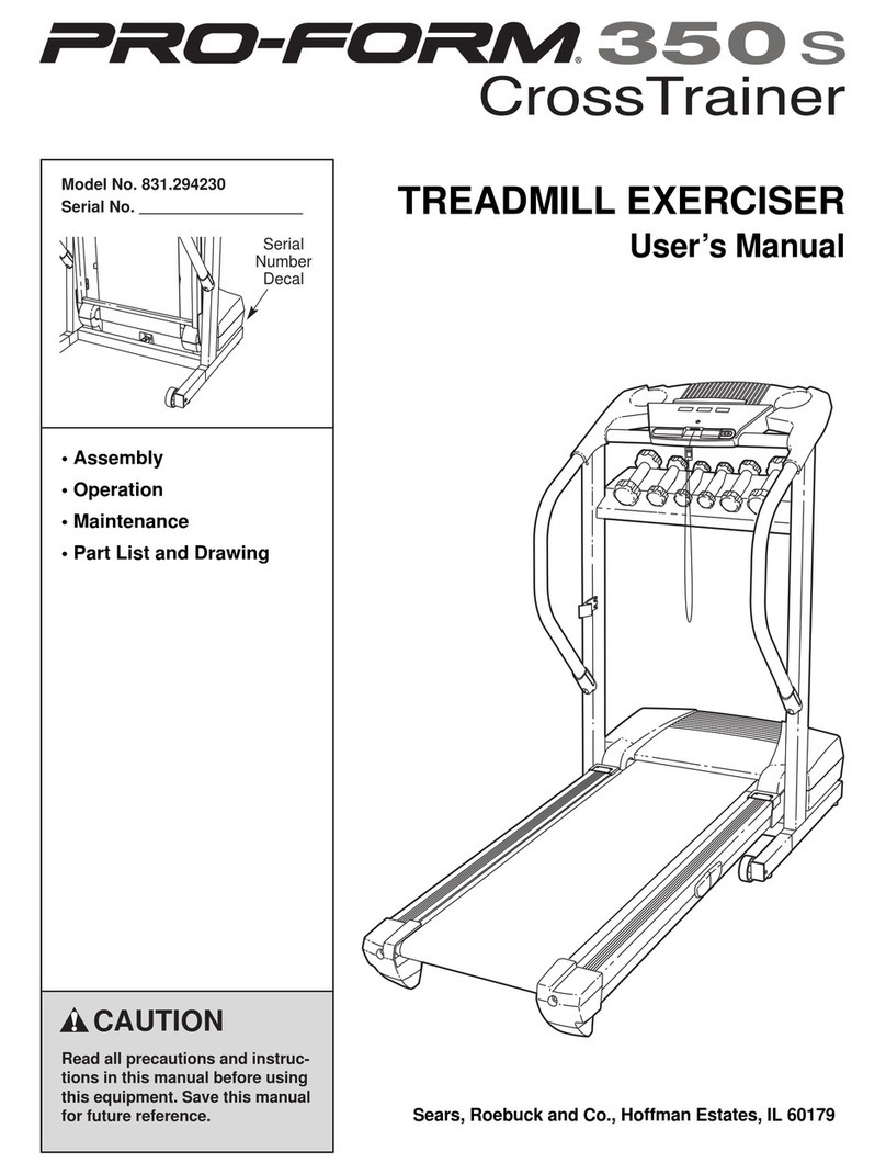
Serial Number Decal
Model No. 831.293062
Serial No.
CAUTION
Read all precaution and in truc-
tion in thi manual before u ing
thi equipment. Save thi manual
for future reference. Sear , Roebuck and Co., Hoffman E tate , IL 60179
TREADMILL EXERCISER
U er’ Manual
• A embly
• Operation
• Maintenance
• Part Li t and Drawing
TABLE OF CONTENTS
IMPORTANT PRECAUTIONS . . . . . . . . . . . . . . . . . . . . . . . . . . . . . . . . . . . . . . . . . . . . . . . . . . . . . . . . . . . . . . . .2
BEFORE YOU BEGIN . . . . . . . . . . . . . . . . . . . . . . . . . . . . . . . . . . . . . . . . . . . . . . . . . . . . . . . . . . . . . . . . . . . . . .4
ASSEMBLY . . . . . . . . . . . . . . . . . . . . . . . . . . . . . . . . . . . . . . . . . . . . . . . . . . . . . . . . . . . . . . . . . . . . . . . . . . . . . . .
OPERATION AND ADJUSTMENT . . . . . . . . . . . . . . . . . . . . . . . . . . . . . . . . . . . . . . . . . . . . . . . . . . . . . . . . . . . . .8
HOW TO FOLD AND MOVE THE TREADMILL . . . . . . . . . . . . . . . . . . . . . . . . . . . . . . . . . . . . . . . . . . . . . . . . . .21
TROUBLESHOOTING . . . . . . . . . . . . . . . . . . . . . . . . . . . . . . . . . . . . . . . . . . . . . . . . . . . . . . . . . . . . . . . . . . . . .22
CONDITIONING GUIDELINES . . . . . . . . . . . . . . . . . . . . . . . . . . . . . . . . . . . . . . . . . . . . . . . . . . . . . . . . . . . . . . .24
PART LIST . . . . . . . . . . . . . . . . . . . . . . . . . . . . . . . . . . . . . . . . . . . . . . . . . . . . . . . . . . . . . . . . . . . . . . . . . . . . . .26
PART IDENTIFICATION CHART . . . . . . . . . . . . . . . . . . . . . . . . . . . . . . . . . . . . . . . . . . . . . . . . . . . . . . . . . . . . .27
ORDERING REPLACEMENT PARTS . . . . . . . . . . . . . . . . . . . . . . . . . . . . . . . . . . . . . . . . . . . . . . . . . .Back Cover
FULL ONE YEAR WARRANTY . . . . . . . . . . . . . . . . . . . . . . . . . . . . . . . . . . . . . . . . . . . . . . . . . . . . . . .Back Cover
Note: An EXPLODED DRAWING is attached in the center of this manual.
1. It i the re pon ibility of the owner to en ure
that all u er of thi treadmill are adequately
informed of all warning and precaution .
2. U e the treadmill only a de cribed.
3. Place the treadmill on a level urface, with at
lea t eight feet of clearance behind it and two
feet on each ide. Do not place the treadmill
on any urface that block air opening . To
protect the floor or carpet from damage, place
a mat under the treadmill.
4. Keep the treadmill indoor , away from moi -
ture and du t. Do not put the treadmill in a
garage or covered patio, or near water.
5. Do not operate the treadmill where aero ol
product are u ed or where oxygen i being
admini tered.
6. Keep children under the age of 12 and pet
away from the treadmill at all time .
7. The treadmill hould be u ed only by per on
weighing 250 pound or le .
8. Never allow more than one per on on the
treadmill at a time.
9. Wear appropriate exerci e clothe when
u ing the treadmill. Do not wear loo e clothe
that could become caught in the treadmill.
Athletic upport clothe are recommended for
both men and women. Always wear athletic
shoes. Never use the treadmill with bare feet,
wearing only stockings, or in sandals.
10. When connecting the power cord ( ee page 8),
plug the power cord into a urge uppre or
(not included) and plug the urge uppre or
into a grounded circuit capable of carrying 15
or more amp . No other appliance hould be on
the ame circuit. Do not u e an exten ion cord.
11. U e only a ingle-outlet urge uppre or that
meet all of the pecification de cribed on
page 8. To purcha e a urge uppre or, ee
your local Sear or call 1-800-366-7278 and
order part number 146148.
12. Failure to u e a properly functioning urge
uppre or could re ult in damage to the con-
trol y tem of the treadmill. If the control y -
tem i damaged, the walking belt may change
peed or top unexpectedly, which may re ult
in a fall and eriou injury.
13. Keep the power cord and the urge uppre -
or away from heated urface .
14. Never move the walking belt while the power
i turned off. Do not operate the treadmill if
the power cord or plug i damaged, or if the
treadmill i not working properly. (See BE-
FORE YOU BEGIN on page 4 if the treadmill i
not working properly.)
WARNING:To reduce the ri k of burn , fire, electric hock, or injury to per on , read the
following important precaution and information before operating the treadmill.
IMPORTANT PRECAUTIONS
2
The decal hown have been placed on your treadmill. If a
decal i mi ing, or if it i not legible, plea e call toll-free
1-800-999-3756 to order a free replacement decal. Apply the
decal in the location hown. Note: The decal are not
hown at actual ize.
15. Never tart the treadmill while you are tand-
ing on the walking belt. Alway hold the
handrail while u ing the treadmill.
16. The treadmill i capable of high peed .
Adju t the peed in mall increment to
avoid udden jump in peed.
17. Never leave the treadmill unattended while it
i running. Alway remove the key, unplug
the power cord and move the on/off circuit
breaker to the off po ition when the treadmill
i not in u e. (See the drawing on page 4 for
the location of the on/off circuit breaker.)
18. Do not attempt to rai e, lower, or move the
treadmill until it i properly a embled. (See
ASSEMBLY on page 5, and HOW TO FOLD
AND MOVE THE TREADMILL on page 21.)
You mu t be able to afely lift 45 pound (20
kg) to rai e, lower, or move the treadmill.
19. When folding or moving the treadmill, make
ure that the torage latch i fully clo ed.
20. When u ing iFIT.com CD and video , an
electronic “chirping” ound will alert you
when the peed of the treadmill i about to
change. Alway li ten for the “chirp” and be
prepared for peed change . In ome in-
tance , the peed may change before the
per onal trainer de cribe the change.
21. When u ing iFIT.com CD and video , you
can manually override the peed etting at
any time by pre ing the peed button .
However, when the next “chirp” i heard, the
peed will change to the next etting for the
CD or video program.
22. Remove iFIT.com CD and video from your
CD player or VCR when you are not u ing
them.
23. In pect and properly tighten all part of the
treadmill regularly.
24. Never in ert any object into any opening.
25. DANGER:Alway unplug the power
cord immediately after u e, before cleaning the
treadmill, and before performing the mainte-
nance and adju tment procedure de cribed in
thi manual. Never remove the motor hood un-
le in tructed to do o by an authorized er-
vice repre entative. Servicing other than the
procedure in thi manual hould be performed
by an authorized ervice repre entative only.
26. Thi treadmill i intended for in-home u e
only. Do not u e thi treadmill in a commer-
cial, rental, or in titutional etting.
SAVE THESE INSTRUCTIONS
WARNING:Before beginning thi or any exerci e program, con ult your phy ician. Thi
i e pecially important for per on over the age of 35 or per on with pre-exi ting health problem .
Read all in truction before u ing. Sear a ume no re pon ibility for per onal injury or property
damage u tained by or through the u e of thi product.
3
Thank you for selecting the revolutionary PROFORM®
80X treadmill. The 80X treadmill combines ad-
vanced technology with innovative design to help you
get the most from your exercise program in the conve-
nience and privacy of your home. And when you’re not
exercising, the unique 80X treadmill can be folded up,
requiring less than half the floor space of other tread-
mills.
For your benefit, read thi manual carefully before
u ing the treadmill. If you have questions after read-
ing this manual, call 1-800-4-MY-HOME®(1-800-469-
4663).To help us assist you, please note the product
model number and serial number before calling. The
model number of the treadmill is 831.293062. The ser-
ial number can be found on a decal attached to the
treadmill (see the front cover of this manual for the lo-
cation).
Before reading further, please review the drawing
below and familiarize yourself with the labeled parts.
BEFORE YOU BEGIN
4
Handrail
Upright
Storage Latch
Accessory Tray
CD Holder
Fan
Key/Clip
On/Off
Circuit Breaker
Walking Belt
Cushioned Walking Platform
for maximum exercise comfort
Foot Rail
Power Cord
RIGHT SIDE
Rear Roller
Adjustment Bolts
Console
BACK
ASSEMBLY
A embly require two per on . Set the treadmill in a cleared area and remove all packing materials. Do not
dispose of the packing materials until assembly is completed. Note: The underside of the treadmill walking belt is
coated with high-performance lubricant. During shipping, a small amount of lubricant may be transferred to the
top of the walking belt or the shipping carton. This is a normal condition and does not affect treadmill perfor-
mance. If there is lubricant on top of the walking belt, simply wipe off the lubricant with a soft cloth and a mild,
non-abrasive cleaner.
A embly require the included allen wrenche and your own phillip crewdriver
and wire cutter .
1. Make ure that the power cord i unplugged.
To identify mall part , u e the PART IDENTIFICA-
TION CHART on page 27. Note: If a part is not in the
parts bag, check to see if it has been pre-assembled. If
a part i mi ing, call toll-free 1-800-999-3756.
With the help of a second person, carefully raise the
Upright Base (97) to the position shown. Insert one of
the Extension Legs (92) into the Upright Base. (Note: It
may be helpful to tip the Upright Base forward as you in-
sert the Extension Leg.) Make sure that the Warning
Decal (91) is in the location shown.
Insert the other Extension Leg (not shown) in the same
way.
5
2. With the help of a second person, carefully tip the
Upright Base (97) down as shown. (Note: It may be help-
ful to place your foot on one of the Extension Legs [92]
as you tip the Uprights.) Make ure that the Exten ion
Leg remain in the Upright .
Attach each Extension Leg (92) with two Extension Leg
Bolts (96) and two 1/4” Washers (39) as shown. Thread
a Leveling Foot (9 ) into each side of the Upright Base
(97); do not thread the Leveling Feet fully into the
Upright Base.
Attach the two Base Pads (99) to the Upright Base (97)
in the locations shown with two 1” Tek Screws (40).
With the help of a second person, raise the Upright Base
(97) to the vertical position.
96
40
40
99
39
96
92 9
9
96
92
96
97
39
39
97
2
92
97
91
1
99
6
3. Attach the Latch Assembly (82) to the Left Upright (84)
with the two Latch Screws (46). Start both Latch Screws
before tightening either of them. Note: The Latch Screws
may be preattached to the Left Upright.
46
84
82
. Set the Console Base (101) on the Uprights (80, 84). Be
careful not to pinch the Wire (not hown) in the
Upright . Attach the Console Base to each Upright with
two Console Bolts (76) and two Internal Star Washers
(77); start all four Console Bolts before tightening any of
them.
Make sure that the Left and Right Trays (109, 111) are
pressed into the Console Base (101).
76 77
101
76
77
111 109
80
84
3
4. Refer to step 6 and locate the four Upright Bolts (86).
Loosen the Upright Bolts two to three turns.
Refer to drawing 4c. With the help of a second person,
hold the Console Base (101) near the Uprights (80, 84).
Look under the Console Base and locate the wires on
the sides of the Console Base. Make sure that the wires
are not routed through the openings for the Trays (109,
111). Drawing 4a shows the correct route for the wires.
Drawing 4b shows an incorrect route.
Refer to drawing 4c. Cut the plastic ties holding the Wire
Harness (74) and the Pulse Wire in the Uprights (80, 84).
Connect the Wire Harness and the Pulse Wire to the
wires on the sides of the Console Base (101). Make ure
to connect the connector properly ( ee the in et
drawing ). IF THE CONNECTORS ARE NOT CON-
NECTED PROPERLY, THE CONSOLE MAY BE DAM-
AGED WHEN THE POWER IS TURNED ON. The con-
nector hould lide together ea ily and nap into
place. If the connectors do not slide together easily and
snap into place, turn one connector and try again. Insert
the excess Wire Harness and Pulse Wire up into the
Console Base.
Press the Right and Left Top Endcaps (7 , 81) into the
Uprights (80, 84) as shown.
101
111 109
80
7 81
84
77
4a 4b
4c
Correct Incorrect
Pulse
Wire
74
If you purcha e the optional che t pul e en or ( ee
page 20), follow the tep below to in tall the receiver
included with the che t pul e en or.
1. Make ure that the power cord i unplugged. Remove
the indicated Screw (108) and the Access Door (122).
2. Remove the paper from the adhesive pad on the back of
the receiver (A). Orient the receiver o the mall cylin-
der i near the lower edge of the receiver and i fac-
ing the Con ole (107) a hown. Firmly press the re-
ceiver onto the indicated corner of the Access Door
(122). Connect the wire on the receiver to the indicated
wire extending from the Console.
3. Make ure that no wire are pinched. Reattach the
Access Door (122) with the Screw (108). Note: The wires
included with the receiver may be discarded.
8. Make ure that all part are properly tightened before you u e the treadmill. Note: Extra hardware may
be included. Keep the included allen wrenches in a secure place. The large allen wrench is used to adjust the
walking belt (see page 23). To protect the floor or carpet, place a mat under the treadmill.
80
84
6. If the Wheels (not shown) are touching the floor, or if the
treadmill rocks slightly, see HOW TO LEVEL THE
TREADMILL on page 20.
If you wi h to adju t the height of the Upright (80,
84), go to step 7. If the Upright are at the de ired
height, tighten the four Upright Bolts (86) and go to step 8.
7. Note: The Uprights (80, 84) can be attached at three dif-
ferent heights. The Uprights are preattached in the mid-
dle position. Adjusting the Uprights requires two persons.
While a second person holds the Console Base (101) and
the Uprights (80, 84), loosen the four Upright Bolts (86).
Then, remove the two Upright Bolts and Upright Star
Washers (127) from the Right Upright (80). Raise or lower
the Right Upright to the desired height, being careful not
to damage the Wire Harness (74). If the Upright Spacer
(79) falls, press it back onto the Upright Base (97).
Loosely thread the two Upright Bolts and Upright Star
Washers back into the Right Upright and the Upright Base.
Adjust the Left Upright (84) in the same way. (Note: There
are no wires in the Left Upright.) Make ure that both
Upright are at the ame height. Lift the Walking
Platform (13) and make ure it i centered between
the Upright . Retighten all four Upright Bolt (86).
79 101
86 13
127
86
127 74
80
84
97
97
86
86
7
A
107
122 Cylinder
108
7
79
97
6
Wire
Wire
8
OPERATION AND ADJUSTMENT
THE PERFORMANT LUBETM WALKING BELT
Your treadmill features a walking belt coated with
PERFORMANT LUBETM, a high-performance lubricant.
IMPORTANT: Never apply ilicone pray or other
ub tance to the walking belt or the walking plat-
form. Such ub tance will deteriorate the walking
belt and cau e exce ive wear.
HOW TO PLUG IN THE POWER CORD
Your treadmill, like any other type of sophisticated
electronic equipment, can be seriously damaged by
sudden voltage changes in your home’s power.
Voltage surges, spikes, and noise interference can
result from weather conditions or from other appliances
being turned on or off. To decrea e the po ibility of
your treadmill being damaged, alway u e a urge
uppre or with your treadmill ( ee drawing 1 at
the right). To purcha e a urge uppre or, ee
your local Sear or call 1-800-366-7278 and order
part number 146148.
U e only a ingle-outlet urge uppre or that i
UL 1449 li ted a a tran ient voltage urge up-
pre or (TVSS). The urge uppre or mu t have a
UL uppre ed voltage rating of 400 volt or le
and a minimum urge di ipation of 450 joule .
The urge uppre or mu t be electrically rated
for 120 volt AC and 15 amp . There mu t be a
monitoring light on the urge uppre or to indi-
cate whether it i functioning properly. Failure to
u e a properly functioning urge uppre or could
re ult in damage to the control y tem of the
treadmill. If the control y tem i damaged, the
walking belt may change peed or top unexpect-
edly, which may re ult in a fall and eriou injury.
Thi product mu t be grounded. If it should malfunc-
tion or break down, grounding provides a path of least
resistance for electric current to reduce the risk of elec-
tric shock. This product is equipped with a cord having
an equipment-grounding conductor and a grounding
plug. Plug the power cord into a urge uppre or,
and plug the urge uppre or into an appropriate
outlet that i properly in talled and grounded in
accordance with all local code and ordinance .
Important: The treadmill i not compatible with
GFCI-equipped outlet .
This product is for use on a nominal 120-volt circuit,
and has a grounding plug that looks like the plug illus-
trated in drawing 1 below. A temporary adapter that
looks like the adapter illustrated in drawing 2 may be
used to connect the surge suppressor to a 2-pole
receptacle as shown in drawing 2 if a properly
grounded outlet is not available.
The temporary adapter should be used only until a
properly grounded outlet (drawing 1) can be installed
by a qualified electrician.
The green-colored rigid ear, lug, or the like extending
from the adapter must be connected to a permanent
ground such as a properly grounded outlet box cover.
Whenever the adapter is used it must be held in place
by a metal screw. Some 2-pole receptacle outlet box
cover are not grounded. Contact a qualified elec-
trician to determine if the outlet box cover i
grounded before u ing an adapter.
DANGER:Improper connection
of the equipment-grounding conductor can
re ult in an increa ed ri k of electric hock.
Check with a qualified electrician or ervice-
man if you are in doubt a to whether the
product i properly grounded. Do not modify
the plug provided with the product—if it will
not fit the outlet, have a proper outlet
in talled by a qualified electrician.
1
2
Grounded Outlet Box
Grounded Outlet Box
Grounding Plug
Surge Suppressor
Surge Suppressor
Grounding Pin
Adapter
Lug
Metal Screw
Grounded Outlet
Grounding Pin
9
FEATURES OF THE CONSOLE
The treadmill console offers an impressive array of
features that help you get the most from your workouts.
When the manual mode of the console is selected, the
speed and incline of the treadmill can be changed with
the touch of a button. As you exercise, the console will
display instant exercise feedback. You can even mea-
sure your heart rate using the handgrip pulse sensor or
the optional chest pulse sensor (see page 20).
In addition, the console offers six preset workout pro-
grams. Each program automatically controls the speed
and incline of the treadmill as it guides you through an
effective workout. Two pulse programs are also offered.
Each program automatically adjusts the speed and in-
cline of the treadmill to keep your heart rate within a tar-
get range while you exercise.
The console also features iFIT.com interactive technol-
ogy. Having iFIT.com technology is like having a per-
sonal trainer in your home. Using the included audio
cable, you can connect the treadmill to your home
stereo, portable stereo, or computer and play special
iFIT.com CD and video programs (one iFIT.com CD is
included; additional CDs and videocassettes are avail-
able separately). iFIT.com CD and video programs au-
tomatically control the speed and incline of the treadmill
as a personal trainer guides you through every step of
your workout. High-energy music provides added moti-
vation. To purcha e iFIT.com CD or videoca -
ette , call toll-free 1-800-735-0768.
With the treadmill connected to your computer, you
can also go to our Web site at www.iFIT.com and ac-
cess programs directly from the internet. Additional op-
tions are soon to be available. See www.iFIT.com for
more information.
To u e the manual mode of the con ole, follow the
steps beginning on page 10. To u e pre et program ,
see page 12. To u e heart rate program , see page
13. To u e an iFIT.com CD or video program, see
page 17. To u e iFIT.com program directly from
our Web ite, see page 19.
Note: If there are thin sheets of clear
plastic on the console, remove them. Clip
Key
10
HOW TO TURN ON THE POWER
Plug in the power cord (see page 8).
Locate the on/off cir-
cuit breaker near the
power cord. Make
sure that the circuit
breaker is in the on
position.
Stand on the foot rails of the treadmill. Find the clip
attached to the key (see the drawing on page 9)
and slide the clip onto the waistband of your
clothes. Next, route the cord attached to the clip
under the handgrip pul e en or, and insert the
key into the console. After a moment, the displays
and various indicators will light. Te t the clip by
carefully taking a few tep backward until the
key i pulled from the con ole. If the key i not
pulled from the con ole, adju t the po ition of
the clip.
HOW TO USE THE MANUAL MODE
In ert the key fully into the con ole.
See HOW TO TURN ON THE POWER above.
Select the manual mode.
When the key is in-
serted, the manual
mode will be selected.
To reselect the manual
mode, press the
Program Select button
repeatedly until a track
appears in the matrix. Make sure that the indicator
on the iFIT.com button is not lit.
Pre the Start button or the Speed
▲▲
button to
tart the walking belt.
A moment after the button is pressed, the walking
belt will begin to move at 1 mph. Hold the handrails
and begin walking.
As you exercise, change the speed of the walking
belt as desired by pressing the Speed
▼▼
and
▲▲
buttons. Each time a
button is pressed, the
speed setting will
change by 0.1 mph; if a
button is held down, the
speed setting will
change in increments of 0. mph. To change the
speed setting quickly, press the Quick Speed but-
tons. Note: The con ole can di play peed and
di tance in either mile or kilometer . For im-
plicity, all in truction in thi ection refer to
mile .
To stop the walking belt, press the Stop button.
The Time/Pace display will begin to flash. To
restart the walking belt, press the Start button or
the Speed
▲▲
button.
Note: The first time the treadmill is used, observe
the alignment of the walking belt, and align the
walking belt if necessary (see page 23).
Change the incline of the treadmill a de ired.
To change the incline of
the treadmill, press the
Incline
▼▼
and
▲▲
buttons.
Each time a button is
pressed, the incline will
change by 0. %.
Follow your progre with the matrix and the
di play .
The matrix—When the
manual mode or the
iFIT.com mode is se-
lected, the matrix will
display a 1/4-mile track.
As you exercise, the in-
dicators around the track
will light, one at a time, until the entire track is lit.
The track will then darken and begin to light again.
Speed di play—This
display shows the speed
of the walking belt. Note:
When the KM/H indica-
tor is lit, the console will
display speed and dis-
tance in kilometers; when the KM/H indicator is
not lit, the console will display speed and distance
in miles.
5
4
3
2
1
3
2
1
Reset
Position