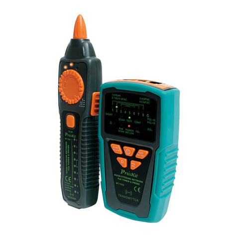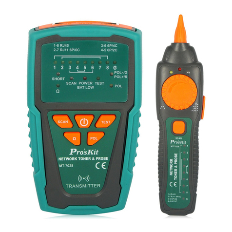
MT-7029N
Noise-Filtering Network PoE Toner & Probe
Thank you for purchasing and using the Pro'sKit MT-7029N
Noise-Filtering Network PoE Toner & Probe. Please read the
instruction manual carefully before using this product, and keep it
properly for future review.
OVERVIEW
MT-7029N is a new high-frequency filter circuit technology, with the
elimination of noise and anti-interference line tracker, Suitable for
ordinary network, PoE network, UTP / STP cable search and
positioning. The interface on the network can be located through the
port flashing function. Diagnosing the straight, short, open, and
crossover conditions of the RJ45 network cable, and RJ11 / 12
telephone cable. Use this instrument to check the cable plug crimping
and confirm the positive and negative polarity of the telephone line.
Accessory aligator clips that can be used to test coaxial cables, general
wiring, and telecommunications / network cables. This product is
suitable for telecommunications, network communication, monitoring,
CATV and other indoor and outdoor wiring construction or
maintenance projects.
INTRODUCTION
Figure1. MT-7029N Transmitter Diagram
1.「Crimping」: RJ45 plug crimping test socket.
2.「POL/Scan」: Scan & Telephone line test socket.
3.「Test/Scan」RJ45 cable map test & scan socket.
4.「1~8/G」Cable map & Shielded indicator
5.「1~8」RJ45 plug crimping test indicator
6.「POWER/BAT LOW」Power ON/OFF & Battery low indicator
7. Function indicator:
「Test」: Cable map & Shielded function indicator
「Scan」: Locating and isolating cables function indicator
「Flash」: Network port flashing function indicator
8. Function indicator
「Crimping」: RJ45 plug crimping test function indicator
「POL」: Telephone line + / - pole test function indicator
「POL-/G,POL+/R」: Phone line polarity indicator
9. 「 」:Power ON/OFF button
10.「Test/Scan」: Cable map test & Scan function button
11.「Flash」: Network port flashing function button
12.「Crimping」:RJ45 Plug crimping test button
13.「TEL/POL」: Phone line polarity function button
14. Battery cover
Figure 2. MT-7029N Receiver Diagram
1. Probe:Used for cable tracing and NCV detection.
2. LED light
3. Power ON/OFF indicator
4. NCV indicator
5. Signal status indicator
6. Volume control
7. Earphone socket (Φ3.5mm)
8. Function switch (LED light/NCV/OFF/SCAN mode)
9. Speaker
10.「 」 Locating and tracing cables function button
11.「1~8/G」Cable map & Shielded indicator
12. RJ45(8 pin)/ RJ11 (6/4/2 pin) cable mapping test socket.
13. Battery cover
SPECIFICATIONS
MT-7029N Transmitter specifications
for RJ45 Lan cable Cat5、5e、6、7(UTP/STP),
RJ11/12 telephone cable
RJ45 Test/Scan socket for RJ45 locating
Individual wire pairs
RJ11 POL/Scan socket for RJ11 locating
Individual wire pairs
Crimping socket for RJ45 、RJ11/RJ12 crystal
plug
1 dual color LED: POL-(Green)/ POL+(Red)
About 7.0V; Power LED flashing.
9V (NEDA 1604/6F22) x1pcs
Tracing/Cable map/Crimping <35mA; Port flash
<110mA
MT-7029N Receiver Specifications
1 LED indicator & speaker, anti-noise and
sensitivity adjustable
1 LED indicator & speaker (AC 90-1000V)
9V (NEDA 1604/6F22) x1pcs
Tracing <200mA; lighting<50mA
RJ45 cable patch cords x2 、RJ11 cable patch
cords x2、RJ11 to alligator clips patch cord x1,
earphone x1, storage bag, user manual
OPERATION
MT-7029N Transmitter:
Do not connect with DC 60V live circuit equipment or it will
result damage.
▲Cable map test:
This function is to check whether the network cable jumper connection
is normal. Network cable connection to the transmitter and receiver, by
viewing the transmitter and receiver 1-8 / G indicator light lit to judge
the network cable connection situation, can test the network cable
straight, short, open, crossover and other faults. You can also use the
transmitter to directly connect to the network switch or the computer
network card to test whether the RJ45 jumper connection is on or
broken. The specific operation is as follows:
1. Insert the pending network cable into the transmitter「Test/Scan」
socket and the other end into the receiver socket.
2. Press the “ ” button, the power indicator is on.
3. Press the「Test / Scan」button , the "Test" indicator will illuminate,
the line order / fault test starts, and the line order indicates of the
LED to start the scanning display.
4. Interpreting the results:
Straight: The LED of the transmitter and receiver will flash
one by one. The “G” indicates shield connection or no
connection.
T: 1-2-3-4-5-6-7-8 T: 1-2-3-4-5-6-7-8-G
R:1-2-3-4-5-6-7-8 R:1-2-3-4-5-6-7-8-G
Crossover: If pin2&5 is cross, when LED2 of the transmitter
lights. LED5 of the receiver light at the same.
T: 1-②-3-4-5-6-7-8 T: 1-2-3-4-⑤-6-7-8
R:1-2-3-4-⑤-6-7-8 R:1-②-3-4-5-6-7-8
Open: If pin 2 is open, the LED2 of the transmitter and the
receiver will not light;
T: 1-X-3-4-5-6-7-8
R:1-X-3-4-5-6-7-8
Short: If pin 4&5 is short, the transmitter 1~8/G LED light up
in order, The 4&5 led in 1-8 / G LED on the receiver are lit
simultaneously, but are dark.
T: 1-2-3-④-5-6-7-8 T: 1-2-3-4-⑤-6-7-8
R:1-2-3-④-⑤-6-7-8 R:1-2-3-④-⑤-6-7-8
The telecom cable map
6P6C: LED 2~7 must light up and the other LED are off.
6P4C: LED 3~6 must light up and the other LED are off.
6P2C: LED 4~5 must light up and the other LED are off.
For telecom cable status indication: crossover、open or short,
Fault display mode is the same as RJ45 network cable.
▲Cables tracking:
This function is used to transmit signals to the network cable through
the transmission signal from the audio transmitter, the receiver
receives the audio signal transmitted by the network cable to find the
target network cable, and can simultaneously check the network cable
connection or disconnection. This product has the characteristics of
signal anti-interference, clear audio sound. Specific operations are as
follows:
1. Connect one end of the target line to be found to the transmitter
「Test / Scan」/RJ45 or 「POL / Scan」/RJ11 socket.
2. Press the transmitter power button to turn on, the "Power / BAT
LOW" light is on, then press the "Test / Scan" button twice, the
"Scan" function light is on, the transmitter begins to transmit the
signal.
3. With the transmitter transmits signals, the line order indicator led
(1-8) will be scanned at the same time and lit in order to easily
determine the connection situation of the network cable. If the
indicator led in the 1-8 indicator lamp is not on, it indicates that the
line is open.
4. The receiver function switch is switched on to the "Scan" or
"lighting" position, and the receiver will "tick", and the receiver
power indicator lights on.
5. The receiver sensitivity adjustment knob rotates clockwise to the
maximum, and then hold down the receiver SCAN button, the
receiver probe close to the network cable, when the receiver
sounded, indicating that the receiver probe touched the network
cable is the target line to be found.
6. When tracing, you must hold the receiver“SCAN”button, release the
button to enter the standby state, and cannot receive the signal.
After work, please turn off in time to save the battery.
7. Maybe several cables near the network interface are ringing same
time (different by network switch) when tracing, this is because the
transmitter transmits audio signal to the internal circuit of the switch
at the same time. you can rotate the receiver sensitivity knob
counter clockwise, reduce the reception sensitivity to achieve to
find the target cable.
▲Plug crimping checking
This function can check whether the network plug quality, just plug in
the transmitter "Crimping" test socket can judge plug pass or fail.
1. Insert the pending network cable into the transmitter「Crimping」
socket.
2. Press the “ ” button then press the「Crimping」button , the "
Crimping " indicator will illuminate.
3. Insert the network cable plug into the transmitter「Crimping」socket,
the crimping "1-8" indicator will illuminated at the same time, if the
indicator light is not on, the plug pin corresponding to the indicator
is not connected to the network wire core. refer figure below, the 2
and 5 lights are not on, indicating that the PLUG second and fifth
pins are not connected to the network cable.
1-X-3-4-X-6-7-8
▲Port Flash
This function transmits the pulsing signal through the transmitter to
flashing the LED indicator of the network switch, then can locate the
interface of the network cable on the switch.
1. Insert the pending network cable into the transmitter「Test/Scan」
socket.
2. Press the “ ” button, then press the「Flash」button , the " Flash
" indicator will illuminate or flashing.
3. Check the indicators of the interface on the network switch, If the
indicator light flashing every about 3 seconds, the corresponding
network interface is the interface you want to find.
▲Telephone line POL +/-
This function is suitable for testing and determining the positive and
negative poles of a telephone line.
1. Insert the alligator clip patch RJ11 into transmitter “ POL / Scan”
socket.
2. Press the “ ” button, then press the「POL TEL」button , the "
POL " indicator will illuminate.
3. Put the red and black alligator clip to the core of the telephone line,
and the indicator light is lit.
4. When the indicator light is bright red, the red alligator is caught on
the positive pole of the telephone line, the black alligator is the
negative pole; when the indicator light is bright green, the red
alligator is caught on the negative and the black alligator is
positive.
▲Non-contact Voltage detection (NCV)
This function is used to determine whether the wire or equipment has
an AC voltage, the detection range AC90-1000V (50 / 60Hz).
Push the receiver function switch to the NCV position, put the
receiver probe close to the target body, if the AC voltage is
detected, the speaker emits an alarm sound of different frequency,
the speaker rapid sound indicates a high voltage or fire line, the
slow sound may be low voltage or zero line.
Note:
This function is for reference, the voltage may still remain even
there is no detection showed up. There are many possible factors
might block the detection.
There are external sources (like flashlight and motor) may trigger
non-contact voltage detection.


