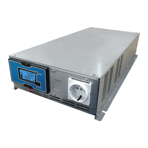
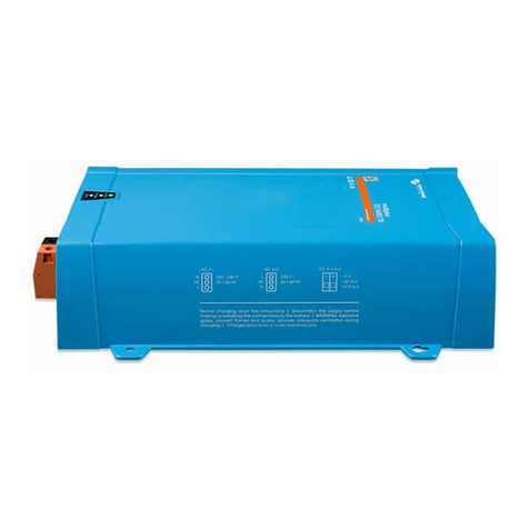
pro user PSI Series User manual

1
PSI-SERIES
PURE SINE WAVE INVERTER WWW.PRO-USER.COM
OPERATING MANUAL P.2
BEDIENUNGSANLEITUNG P.22
GEBRUIKSAANWIJZING P.42
MODE D’EMPLOI P.62
PURE SINE WAVE INVERTER
SINUS WECHSELRICHTER
ZUIVERE SINUS OMVORMER
CONVERTISSEUR DE TENSION PUR SINUS

2
Rea this manual before using this pro uct.
Rea this manual before using this pro uct. Rea this manual before using this pro uct.
Rea this manual before using this pro uct.
Failure to o so can result in serious injury.
Failure to o so can result in serious injury.Failure to o so can result in serious injury.
Failure to o so can result in serious injury.
Intro uction P.3
Important safety instructions P.3
General instructions P.6
Package contents P.6
Technical escription P.7
Remote control P.10
Dipswitch settings (Hybri only) P.11
ECO/UPS function P.11
Installation & operation P.12
Wiring scheme P.13
Troubleshooting P.15
Technical specifications P.19
Maintenance P.21
Warranty P.21
CONTENTS

3
INTRODUCTION
The pure sine wave inverters are a member of the family of a vance mobile power inverters
manufacture by Pro-User Electronics. Your Pro-User Electronics pure sine wave inverter
enables you to generate a pure sine wave 230V AC 50Hz voltage from a 12V DC battery
wherever your travels take you. As a bonus we built-in 1 USB-Port for powering or charging
e.g. your sat nav, cell phone, tablet or any other USB evice. Because of the high quality pure
sine wave voltage an the excellent overloa capabilities, even sensitive electronics will
work flawlessly.
The wire remote control enables you to monitor an control your inverter in a convenient
way.
We have taken numerous measures in quality control to ensure that your pro uct arrives in
top con ition an will perform to your satisfaction.
Please carefully rea an follow the safety an operating instructions. Not following
Please carefully rea an follow the safety an operating instructions. Not following Please carefully rea an follow the safety an operating instructions. Not following
Please carefully rea an follow the safety an operating instructions. Not following
these instructions may result in a serious acci ent, inclu ing amage property, serious
these instructions may result in a serious acci ent, inclu ing amage property, serious these instructions may result in a serious acci ent, inclu ing amage property, serious
these instructions may result in a serious acci ent, inclu ing amage property, serious
or even fatal injuries. If the evice is passe on to another person, this manual must
or even fatal injuries. If the evice is passe on to another person, this manual must or even fatal injuries. If the evice is passe on to another person, this manual must
or even fatal injuries. If the evice is passe on to another person, this manual must
also be han e over with it.
also be han e over with it.also be han e over with it.
also be han e over with it.
CAUTION: Please rea this instruction manual carefully before installing an
CAUTION: Please rea this instruction manual carefully before installing an CAUTION: Please rea this instruction manual carefully before installing an
CAUTION: Please rea this instruction manual carefully before installing an
starting up the evice. Do not operate the inverter unless you have fully rea
starting up the evice. Do not operate the inverter unless you have fully rea starting up the evice. Do not operate the inverter unless you have fully rea
starting up the evice. Do not operate the inverter unless you have fully rea
an un erstoo all the provi e information. If you are not confi ent working
an un erstoo all the provi e information. If you are not confi ent working an un erstoo all the provi e information. If you are not confi ent working
an un erstoo all the provi e information. If you are not confi ent working
with 12V DC voltage or are unsure of what you are oing, consi er to seek for
with 12V DC voltage or are unsure of what you are oing, consi er to seek for with 12V DC voltage or are unsure of what you are oing, consi er to seek for
with 12V DC voltage or are unsure of what you are oing, consi er to seek for
help by a professional installation service or your vehicle´s manufacturer.
help by a professional installation service or your vehicle´s manufacturer. help by a professional installation service or your vehicle´s manufacturer.
help by a professional installation service or your vehicle´s manufacturer.
Failure to observe these instructions may cause an electrical shock, fatal or
Failure to observe these instructions may cause an electrical shock, fatal or Failure to observe these instructions may cause an electrical shock, fatal or
Failure to observe these instructions may cause an electrical shock, fatal or
serious injury, material amage or impair the function of the inverter.
serious injury, material amage or impair the function of the inverter.serious injury, material amage or impair the function of the inverter.
serious injury, material amage or impair the function of the inverter.
Pro-User Electronics accepts no liability for irect or in irect amage cause by faulty
assembly or connection, a usage of amage or altere pro ucts, a usage for purposes other
than escribe an especially cause by failure to follow these instructions.
General:
• Electrical evices are not toys. Keep the pro uct away from chil ren.
• Only use the pro uct as inten e an for purposes escribe in the manual.
• After opening the package, examine all parts for visible amage. If you have foun any
amage, please contact the company you purchase this unit from.
• Always isconnect the power supply (inclu ing the connection to the battery an an optional
solar panel) when working on the evice.
IMPORTANT SAFETY INSTRUCTIONS

4
• Use only approve accessories (especially all cables) or parts fully consistent with the
requirements. The installer is responsible for ensuring that the correct cable an fuse sizes
are use .
• The surface temperature can reach up to 65°C. Power-o an stop using the evice
imme iately, if the unit is smoking or is showing any abnormal behaviour.
• This appliance is not inten e for use by persons (inclu ing chil ren) with re uce physical,
sensory or mental capabilities, or lack of experience an knowle ge, unless they are
supervise or have been instructe on how to use the appliance by a person responsible for
their safety. Chil ren shoul be supervise to ensure that they o not play with the
appliance.
• Installing the evice, maintenance an repair work may only be carrie out by qualifie
person who are familiar with the risks involve , the relevant regulations an with the
gui elines an safety precautions to be applie .
• Do not isassemble the inverter, the internal circuit contains hazar ous voltages.
Attempting to service the unit yourself may result in electric shock or fire an will voi the
unit warranty.
• Always keep metal objects or other materials that can short circuit the terminals of the
battery or the inverter securely away. A resulting spark or short-circuit may not only amage
the evice, but also cause an explosion an potentially pro uce a current high enough to
wel a ring or the like to metal. Remove personal metal items such as rings, bracelets,
necklaces an watches when working on the evice or the battery.
• Operate the inverter only, if all cables an the housing are un amage an all connections
are tight an clean. Loose or irty connections coul result in overheating, electrical sparks
an fire.
• Do not connect AC output terminals of the inverter to an incoming AC source (or the gri ).
• Do not connect DC input terminals of the inverter to an incoming AC source.
• Never use the inverter on vehicles where the positive terminal of the battery is connecte to
the chassis.
• Never connect cables in reverse polarity or short-circuit connecte cables. This may blow
internal fuses an may amage the inverter permanently.
• A fuse shoul be provi e at a istance of max. 30 cm from the battery´s positive terminal.
Failure to o so, may cause amage to the cabling or battery if a fault (e.g. over-current or
short circuit) occurs. Only use high quality copper cable an keep the cable length short.
• Do not operate appliances that may fee AC main power back into the inverter. This might
amage the inverter.
• Ensure the evice is stan ing firmly. The evice must be set up an fastene in such a way
that it cannot tip over or fall own.
• Never connect evices that have a higher power requirement than the peak output power of
the inverter. Note that some evices may require more starting current than the type plate of
the evice in icates.
Working with Batteries
Working with BatteriesWorking with Batteries
Working with Batteries
• Batteries can store large amounts of energy an improper han ling can be angerous. Never
connect to a battery with an unsuite voltage or other unsuitable or amage batteries.
• Keep chil ren away from batteries an aci .

5
• Avoi getting electrolyte on your skin or clothes. It is aci ic an can cause burns. If battery
aci contacts skin or clothing, wash imme iately with water. Baking so a neutralizes lea
aci battery electrolyte. If electrolyte gets into your eyes, imme iately floo your eyes with
running col water for at least 20 minutes an get me ical attention imme iately. Eye
protection is therefore recommen e .
• Always keep metal objects or other materials that can short circuit the terminals of the
battery or the inverter securely away.
• Power-o the evice before making or breaking the connections to the battery.
• Observe technical instructions of the seller or the manufacturer of your battery.
• Check if all connections are tight an clean. Loose or irty connections coul result in
overheating, electrical sparks an fire. Use terminal grease where require .
• Never smoke or allow a spark or flame in vicinity of the battery.
• Never try to charge a amage or frozen battery.
• Do not place the evice irectly on top of the battery or vice versa or on a surface
constructe from combustible material.
• Rea your car´s owner's manual. Some vehicle manufacturers may have special requirements
before charging or ischarging the vehicle´s battery (e.g. fuses that have to be remove or
certain security eman s).
Environment
EnvironmentEnvironment
Environment
• Only use the pro uct in environments from 0°C ~ 45°C.
• Do not operate the pro uct in amp, wet or usty environments: Never expose the inverter
to rain or snow. Doing so may result in amage to the inverter or other equipment installe in
the system or result in electric shock or fire. Do not operate the unit in explosive
atmospheres, such as in the presence of flammable liqui s, gases or ust. Do not put
batteries, or anything that shoul be protecte from sparks aroun the inverter. Doing so
may result in fire or explosion.
• To avoi heat accumulation, o not cover the evice. To prevent overheating , ensure that air
inlets an ventilation is not obstructe . Do not expose the evice to a heat source (such as
irect sunlight or heating). Avoi a itional heating of the evice in this way.
Electrical Cables
Electrical CablesElectrical Cables
Electrical Cables
• If cables have to be fe through metal holes or other walls with sharp e ges, use ucts or
cable bushings to prevent amage.
• Do not lay cables which are loose or bent next to electrically con uctive material (metal).
• Do not pull on the cables.
• Avoi to lay 230 V AC mains cable an 12 V DC cables in the same uct.
• Prevent all cables from being steppe on, trippe over, or being amage by e.g. sharp e ges
or hot surfaces.

6
GENERAL INSTRUCTIONS
Inten e use
Inten e useInten e use
Inten e use
The Pro-User Electronics pure sine wave inverter converts a 12V irect current voltage
(e.g. a battery or another 12V source that can eliver the require current) into 200-240V
50Hz AC pure sine wave voltage. The built-in USB-port is inten e to power or charge 5V
USB evices (the maximum current elivery has to be kept in min ). The wire remote control
enables the user to monitor an control the inverter in a convenient way.
Packaging materials
Packaging materialsPackaging materials
Packaging materials
To avoi anger of suocation, o not let chil ren play with foils or other packaging
materials. Remove all protective coverings before putting the evice in operation.
Storage
StorageStorage
Storage
When not in use, store the inverter in a ry environment. Store the evice in a safe place out
of the reach of chil ren. Protect the unit from irect sunlight, heat an moisture.
• 1x Pro-User Electronics pure sine wave inverter
• 1x Remote control (600/1000/1500/2000/3000W)
• 1x Remote control wiring (600/1000/1500/2000/3000W)
• 1x Remote control surface mounting frame (600/1000/1500/2000/3000W)
• 1x Battery wiring set
• 1x 230V connection cable (1000/1500/2000W)
• 1x Operating manual
PACKAGE CONTENTS

7
TECHNICAL DESCRIPTION
A
C
D
E
B
F
G
H
A) Incoming 230V AC connection (1000W / 1500W / 2000W)
B) Output 230V AC socket
C) ECO mo e in ication le (1000W / 1500W / 2000W / 3000W)
D) Power switch
E) Remote control wiring connection
F) UPS in ication le (1000W / 1500W / 2000W / 3000W)
G) Inverter function in ication le
H) Fault in ication le
I) AC incoming in ication le
J) USB output
K) BY-Pass in ication le
I
J
K

8
TECHNICAL DESCRIPTION
A B
A) Positive battery terminal ( re / + )
B) Negative battery terminal ( black / - )
C) Cooling vents
C

9
TECHNICAL DESCRIPTION 3000W & HYBRID PSI-SERIES
E
F
G
B C
A) Solar panel input (MC4 Hybri only)
B) Output 230V AC connections
C) Input 230V AC connection
D) Battery setup ipswitches (Hybri only)
E) ECO mo e in ication le
F) Power switch
G) Remote control wiring connection
H) UPS in ication le
I) Solar charge function in ication le (Hybri only)
J) Inverter function in ication le
K) 230V AC charge function in ication le (Hybri only)
L) Fault in ication le
M) AC incoming in ication le
N) USB output
O) BY-Pass in ication le
D
H
I
J
K
L
M
N
O
A

10
A
B
C
D
E
F
REMOTE CONTROL DISPLAY INVERTER MODE
A) Battery In ication
B) Battery voltage
C) AC output running
D) Power consumption
E) AC output voltage
F) Inverter operating
REMOTE CONTROL DISPLAY TRANSFERSWITCH MODE (1000W / 1500W /2000W /3000W)
D
E
F
A
B
C
A) Battery In ication
B) Battery voltage
C) AC output running
D) Power consumption
E) AC output voltage
F) Mains connecte (transferswitch/By-pass)

11
A
B
E
F
G
A) Battery In ication
B) Battery voltage
C) Solar panel connecte
D) AC output running
E) Power consumption
F) AC output voltage
G) Inverter operating
The inverter is equippe with ECO (energy saving) an UPS setting. In ECO mo e,
consumption from the battery is preferre . This way, no external incoming voltage is applie
as long as there is sucient capacity from the battery. If you choose the UPS mo e ( efault
setting) then external incoming 230V AC voltage is preferre (bypass). In UPS mo e, the
battery is selecte when no external incoming voltage is available.
To switch from UPS to ECO or vice versa, press an hol the power button for 2
2 2
2 secon s.
C D
DIPSWITCH SETTINGS (HYBRID ONLY)
The battery charger function is set using the ip switches on the si e of the inverter. The
iagram below shows how to set them. When in oubt about which setting you nee , please
contact your battery supplier.
ECO/UPS FUNCTION (1000/1500/2000/3000W)
REMOTE CONTROL DISPLAY MPPT SOLAR MODE (HYBRID ONLY)

12
INSTALLATION & OPERATION
WARNING: Please rea this instruction manual carefully before installing an
WARNING: Please rea this instruction manual carefully before installing an WARNING: Please rea this instruction manual carefully before installing an
WARNING: Please rea this instruction manual carefully before installing an
starting up the evice. Do not operate the inverter unless you have fully rea
starting up the evice. Do not operate the inverter unless you have fully rea starting up the evice. Do not operate the inverter unless you have fully rea
starting up the evice. Do not operate the inverter unless you have fully rea
an un erstoo all the provi e information. If you are not confi ent working
an un erstoo all the provi e information. If you are not confi ent working an un erstoo all the provi e information. If you are not confi ent working
an un erstoo all the provi e information. If you are not confi ent working
with 12V DC voltage or are unsure of what you are oing, consi er to seek for
with 12V DC voltage or are unsure of what you are oing, consi er to seek for with 12V DC voltage or are unsure of what you are oing, consi er to seek for
with 12V DC voltage or are unsure of what you are oing, consi er to seek for
help by a professional installation service or your vehicle´s manufacturer.
help by a professional installation service or your vehicle´s manufacturer. help by a professional installation service or your vehicle´s manufacturer.
help by a professional installation service or your vehicle´s manufacturer.
Failure to observe these instructions may cause an electrical shock, fatal or
Failure to observe these instructions may cause an electrical shock, fatal or Failure to observe these instructions may cause an electrical shock, fatal or
Failure to observe these instructions may cause an electrical shock, fatal or
serious injury, material amage or impair the function of the inverter.
serious injury, material amage or impair the function of the inverter.serious injury, material amage or impair the function of the inverter.
serious injury, material amage or impair the function of the inverter.
WARNING: Before installing the inverter, please ensure the main switch is set to
WARNING: Before installing the inverter, please ensure the main switch is set to WARNING: Before installing the inverter, please ensure the main switch is set to
WARNING: Before installing the inverter, please ensure the main switch is set to
position
position position
position “
““
“OFF
OFFOFF
OFF”.
”. ”.
”. Make sure the battery poles are clean when connecting the
Make sure the battery poles are clean when connecting the Make sure the battery poles are clean when connecting the
Make sure the battery poles are clean when connecting the
terminals. Tighten the nuts an bolts to a torque of 12
terminals. Tighten the nuts an bolts to a torque of 12terminals. Tighten the nuts an bolts to a torque of 12
terminals. Tighten the nuts an bolts to a torque of 12-
--
-13 Nm. Loose or irty
13 Nm. Loose or irty 13 Nm. Loose or irty
13 Nm. Loose or irty
connections may cause overheating.
connections may cause overheating.connections may cause overheating.
connections may cause overheating.
Risk of electrical shock: Operation of the inverter without a proper groun
Risk of electrical shock: Operation of the inverter without a proper groun Risk of electrical shock: Operation of the inverter without a proper groun
Risk of electrical shock: Operation of the inverter without a proper groun
connection may result in an electrical safety hazar . Ensure proper groun
connection may result in an electrical safety hazar . Ensure proper groun connection may result in an electrical safety hazar . Ensure proper groun
connection may result in an electrical safety hazar . Ensure proper groun
connection is ma e uring installation. Do not reverse the polarity. Reversing
connection is ma e uring installation. Do not reverse the polarity. Reversing connection is ma e uring installation. Do not reverse the polarity. Reversing
connection is ma e uring installation. Do not reverse the polarity. Reversing
the polarity of the connections may cause a spark an melt internal fuses.
the polarity of the connections may cause a spark an melt internal fuses.the polarity of the connections may cause a spark an melt internal fuses.
the polarity of the connections may cause a spark an melt internal fuses.
Observe the relevant regulations an irectives of your country! In some
Observe the relevant regulations an irectives of your country! In some Observe the relevant regulations an irectives of your country! In some
Observe the relevant regulations an irectives of your country! In some
country there might be legal regulations that require RCD protection of AC
country there might be legal regulations that require RCD protection of AC country there might be legal regulations that require RCD protection of AC
country there might be legal regulations that require RCD protection of AC
output connections of installations (Resi ual
output connections of installations (Resi ualoutput connections of installations (Resi ual
output connections of installations (Resi ual-
--
-current evice, also known as
current evice, also known as current evice, also known as
current evice, also known as
RCCB/GFCI). RCDs may be fitte by a licence electrician in installations.
RCCB/GFCI). RCDs may be fitte by a licence electrician in installations.RCCB/GFCI). RCDs may be fitte by a licence electrician in installations.
RCCB/GFCI). RCDs may be fitte by a licence electrician in installations.
Fastening the inverter
Fastening the inverterFastening the inverter
Fastening the inverter
When selecting the installation location, observe the following instructions:
• The inverter can be mounte horizontally or vertically.
• The installation surface must be level an suciently stur y.
• The inverter must be installe in a place that is protecte from irt, ust an moisture.
• The inverter may not be installe in the presence of flammable materials.
• The place of installation must be well-ventilate . A ventilation system must be present for
installations in small, close spaces.
• The minimum clearance aroun the inverter shoul be at least 25 cm.
• Do not block or cover the ventilation holes. Be sure to keep a istance (at least 1 inch) from
surroun ing objects.
Wiring & Cables
Wiring & CablesWiring & Cables
Wiring & Cables
A fuse shoul be provi e at a istance of max. 30 cm from the battery´s positive
terminal. Failure to o so, may cause amage to the cabling or battery if a fault
(e.g. over-current or short circuit) occurs.
Reverse polarity connection may blow the internal fuse an may amage the
inverter permantly.

13
+ -
Fuse
(not inclu e )
Input 230V AC Output 230V AC Remote control
(1000/1500/2000W) (600/1000/1500/2000W)
Groun
WIRING SCHEME

14
+ -
Fuse
(not inclu e )
Output 230V AC Input 230V AC Remote control
Groun
WIRING SCHEME 3000W & HYBRID PSI-SERIES
Solar Panel
(Hybri only)
-
--
-
+
++
+

15
Setting
SettingSetting
Setting-
--
-up the inverter
up the inverterup the inverter
up the inverter
To set up the inverter, use the appropriate cables to:
• connect the positive pole (usually marke with + or coloure in re ) of the battery an the
positive pole (coloure in re ) of the inverter.
• connect the negative pole (usually marke with - or coloure in black) of the battery an the
negative pole (coloure in black) of the inverter.
• Automatic Transfer Switch function (by-pass 1000/1500/2000/3000W only).
Connect the 230V AC incoming connection to the input connection using the supplie cable
(not inclu e with 3000W/Hybri ). The by-pass function will automatically take eect when
a 230V AC external source is connecte (UPS mo e). When the external source fails, the
inverter function switches on automatically.
Ensure to clamp all cables securely.
Ensure to clamp all cables securely.Ensure to clamp all cables securely.
Ensure to clamp all cables securely.
The Inverter is now rea y to use:
The Inverter is now rea y to use: The Inverter is now rea y to use:
The Inverter is now rea y to use: Push the main switch to power on the evice.
Please notice the evice functions escribe in chapter "TECHNICAL DESCRIPTION"
NOTE: You can operate the inverter with your vehicle´s engine running or switche o.
NOTE: You can operate the inverter with your vehicle´s engine running or switche o. NOTE: You can operate the inverter with your vehicle´s engine running or switche o.
NOTE: You can operate the inverter with your vehicle´s engine running or switche o.
However, it is recommen e to switch o the inverter while starting the engine.
However, it is recommen e to switch o the inverter while starting the engine.However, it is recommen e to switch o the inverter while starting the engine.
However, it is recommen e to switch o the inverter while starting the engine.
USB port
USB portUSB port
USB port
Connect the USB external appliance to the USB port an switch it on. The USB port on the
power inverter provi es a power supply of 5V DC for external USB evices.
Remote Port
Remote PortRemote Port
Remote Port
Connect the remote unit to the remote connection port.
Solar panel connection (MC4 connectors). Hybri PSI series only.
Solar panel connection (MC4 connectors). Hybri PSI series only.Solar panel connection (MC4 connectors). Hybri PSI series only.
Solar panel connection (MC4 connectors). Hybri PSI series only.
Install your solar panel on the MC4 connectors. The system itself recognizes the connection
an the charging function of the MPPT controller takes eect.
Battery ipswitches settings. Hybri PSI series only.
Battery ipswitches settings. Hybri PSI series only.Battery ipswitches settings. Hybri PSI series only.
Battery ipswitches settings. Hybri PSI series only.
To optimally charge your batteries, the Hybri inverter is equippe with ip switches. See
chapter ipswitch settings for the correct settings for your battery.
TROUBLESHOOTING
WARNING! Do not open or isassemble the Inverter. Attempting to service the
WARNING! Do not open or isassemble the Inverter. Attempting to service the WARNING! Do not open or isassemble the Inverter. Attempting to service the
WARNING! Do not open or isassemble the Inverter. Attempting to service the
unit yourself may cause the risk of electrical shock or fire. Please follow the
unit yourself may cause the risk of electrical shock or fire. Please follow the unit yourself may cause the risk of electrical shock or fire. Please follow the
unit yourself may cause the risk of electrical shock or fire. Please follow the
safety instructions when working on the evice.
safety instructions when working on the evice.safety instructions when working on the evice.
safety instructions when working on the evice.
If the evice oesn’t work at all, an internal fuse might be blown. This happens always for a
reason. Maybe there has been a short circuit, when connecting the inverter in wrong polarity.
Don´t try to replace internal fuses yourself. The inverter has to be checke by the
manufacturer or by an authorize service.

16
The main Switch is ON, but
there is no 230V AC out-
put or any LED in icator
lights on.
There is no voltage at
the DC input.
• Check that the battery
fuse is not blown an in-
tact.
• Check that all the DC input
connections are tight.
• Check the continuity of
the DC input circuit.
• If using a lithium battery,
check to see if it as gone
into protection/safe mo e,
if so, please follow your
battery manufacturer’s
instructions on how to
reset the battery.
The polarity of the DC
input has been reverse
an blown the internal
fuses.
(NOTE: This may have
cause permanent ama-
ge to the inverter, an
voi all warranty).
The inverter will nee to
be returne to Pro-User
Electronics for further
assessment.
The inverter beeps once,
Power LED in icator is
green. But the connecte
AC appliance oes not turn
on.
• Loose AC output
connections.
• Short circuit of AC output
wiring.
• The AC appliance is
faulty.
• The AC appliance is swit-
che o.
• Double check that all AC
output connections are
tight an not loose
(Consult a license
electrician).
• Check for short circuits
with your AC wiring.
• Test the AC appliance on a
230V AC socket.
• If there is still no output,
contact Pro-User
Electronics.
Symptom Possible Cause Solutions
TROUBLESHOOTING

17
The inverter beeps twice. Low DC input voltage
warning. The voltage at
the DC input is below
10.5 + 0.5V DC.
• Check that the battery is
not flat an fully charge ,
recharge if low.
• Check that the battery
cables are thick enough to
carry the require current
over the require length.
Use thicker cable if
require .
• Check for any loose
connections on the DC
input circuit.
The inverter beeps three
times, the re fault
in icator LED illuminates
an there is no AC output.
Low DC input voltage
protecte warning. The
voltage at the DC input is
below 10 + 0.5 V DC.
• Check that the battery is
not flat an fully charge ,
recharge if low.
• Check that the battery
cables are thick enough to
carry the require current
over the require length.
Use thicker cable if
require .
• Check for any loose
connections on the DC
input circuit.
The inverter beeps four
times, the re fault
in icator LED illuminates
an there is no AC output.
Overvoltage etecte on
the DC input. When the
voltage at the DC input is
higher than 16 +0.5V DC
the AC output will shut
own.
• Check that the voltage at
the DC input terminals o
not excee 16.0V DC if so,
attempt to lower the
voltage of the battery an
check battery charging
voltages.
• Ensure that maximum
charging voltage of any
chargers (e.g. solar
controller) connecte to
the battery are set below
16.0V DC.
Symptom Possible Cause Solutions
TROUBLESHOOTING

18
The inverter beeps five
times, the re fault
in icator LED Illuminates
an there is no AC output.
The inverter is
overheating. When the
internal temperature
excee s 75°C the AC
output will shut own.
• Reset the inverter by
turning it o an on again
an check to see if the
cooling fans are working
(fans automatically turn
on when the inverter is at
20% loa or internal
temperatures are at
45°C). If the cooling fans
are not functioning, the
inverter will nee further
assessment, please
contact Pro-User
Electronics.
• If the fans are
functioning, check that all
ventilation slots an fan
openings are not
obstructe . Also ensure
that cool air is being
circulate to the inverter
an make sure ambient
temperatures o not
excee 45°C.
The inverter beeps
eleven times, the re
fault in icator LED
illuminates an the
inverter shuts own.
The inverter has etecte
a short circuit at the AC
output.
Please check that the
connecte evice is not
faulty an check if there
are no short circuits in the
AC circuit.
The inverter is beeping
Continuously, the re
fault in icator LED
Illuminates an there is no
AC output.
The inverter has shut
own ue to overloa .
Connecte loa has
excee e the surge
rating of the inverter.
• Disconnect the connecte
loa .
• Re uce the connecte
loa .
Symptom Possible Cause Solutions
TROUBLESHOOTING

19
TECHNICAL SPECIFICATIONS
Mo el PSI300 PSI400 PSI600 PSI1000TX
Battery Voltage 10.5V — 16V 10.5V — 16V 10.5V — 16V 10.5V — 16V
Stan by Current <0.25A <0.35A <0.46A <0.56A
Recommen e
Battery Capacity
SLA/Gel/AGM:
>40Ah
SLA/Gel/AGM:
>50Ah
SLA/Gel/AGM:
> 100Ah
SLA/Gel/AGM:
>160Ah
AC Output Voltage 230V 230V 230V 230V
Frequency 50Hz 50Hz 50Hz 50Hz
Rate Output Power 300W 400W 600W 1000W
Surge Power 450W (10s) 600W (10s) 900W (10s) 1500W (10s)
Peak Power 600W (2s) 800W (2s) 1200W (2s) 2000W (2s)
Eciency >90% >90% >90% >90%
USB Output 5V / 2.1A 5V / 2.1A 5V / 2.1A 5V / 2.1A
Dimensions LxWxH 165x150x75mm
(housing)
215x150x75mm
(incl. terminals)
185x150x75mm
(housing)
235x150x75mm
(incl. terminals)
215x150x75mm
(housing)
265x150x75mm
(incl. terminals)
355x150x75mm
(housing)
405x150x75mm
(incl. terminals)
Weight 1.4kg 1.6kg 1.9kg 2.8kg
Operating -15°C — 40°C -15°C — 40°C -15°C — 40°C -15°C — 40°C
Storage Temperature -40°C — 85°C -40°C — 85°C -40°C — 85°C -40°C — 85°C
Cooling Air-Coole Air-Coole Air-Coole Air-Coole
Remote Control with
wiring
Optional Optional Inclu e Inclu e
Battery Wiring 4mm2 (80cm) 4mm2 (80cm) 6mm2 (80cm) 10mm2 (80cm)
Transferswitch No No No Yes

20
TECHNICAL SPECIFICATIONS
Mo el PSI1500TX PSI2000TX PSI3000TX PSI3000TX Hybri
Battery Voltage 10.5V — 16V 10.5V — 16V 10.5V — 16V 10.5V — 16V
Stan by Current <0.65A <0.7A <1.2A <1.2A
Recommen e
Battery Capacity
SLA/Gel/AGM:
>250Ah
SLA/Gel/AGM:
>320Ah
SLA/Gel/AGM:
> 480Ah
SLA/Gel/AGM:
>480Ah
AC Output Voltage 230V 230V 230V 230V
Frequency 50Hz 50Hz 50Hz 50Hz
Rate Output Power 1500W 2000W 3000W 3000W
Surge Power 2250W (10s) 3000W (10s) 4500W (10s) 4500W (10s)
Peak Power 3000W (2s) 4000W (2s) 6000W (2s) 6000W (2s)
Eciency >90% >90% >90% >90%
USB Output 5V / 2.1A 5V / 2.1A 5V / 2.1A 5V / 2.1A
Dimensions LxWxH 320x220x90mm
(housing)
380x220x85mm
(incl. terminals)
385x220x85mm
(housing)
440x220x85mm
(incl. terminals)
415x220x150mm
(housing)
510x220x150mm
(incl. terminals)
415x220x150mm
(housing)
515x220x150mm
(incl. terminals)
Weight 4.1kg 5.0kg 7.6kg 8.6kg
Operating
Temperature
-15°C — 40°C -15°C — 40°C -15°C — 40°C -15°C — 40°C
Storage Temperatu-
re
-40°C — 85°C -40°C — 85°C -40°C — 85°C -40°C — 85°C
Cooling Air-Coole Air-Coole Air-Coole Air-Coole
Remote Control with
wiring
Inclu e Inclu e Inclu e Inclu e
Battery Wiring 16mm2 (80cm) 25mm2 (80cm) 35mm2 (80cm) 35mm2 (80cm)
Transferswitch
(by-pass)
Yes Yes Yes Yes
Solar Connection
MC4
No No No Yes
MPPT Charger 20A No No No Yes
Battery Charger 20A No No No Yes
This manual suits for next models
8
Table of contents
Languages:
Other pro user Inverter manuals
