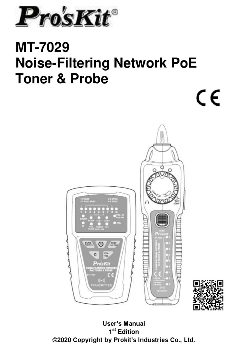
Procentec PROFINET User manual

Version 1.2.1 – June 2014
User Manual
PROFINET Cable Tester
4- and 8-wire industrial PROFINET cable
Straight and 90° metal or plastic PROFINET plugs
Regular Ethernet cable and plugs
Shielding
Wire breaks
Short circuits
Swaps
Miswiring
Split pairs
Can also test telephone and coax cable

Version 1.2.1 – June 2014
Copyright © 2014 PROCENTEC
All rights reserved. No part of this publication may be reproduced, stored in a retrieval system, or
transmitted, in any form or by any means, electronic, mechanical, photocopying, recording or
otherwise, without the prior written permission of the publisher.
Safety Guidelines
This manual contains notices which you should observe to ensure your own personal safety, as well
as to protect the product and connected equipment. These notices are highlighted in the manual by a
warning sign and are marked as follows according to the level of danger:
Draws your attention to important information on handling the product, a particular part of the
documentation or the correct functioning of the product.
Warning
This device and its components may only be used for the applications described in this manual and
only in connection with devices or components that comply with the Ethernet standard.
This product can only function correctly and safely if it is transported, stored, set up, installed,
operated and maintained as recommended.
Do NOT attach to AC power. The cable tester may be damaged and can cause a safety hazard for the
user.
Disclaimer of Liability
We have checked the contents of this manual as much as possible. Since deviations cannot be
precluded entirely, we cannot guarantee full agreement. However, the content in this manual is
reviewed regularly and any necessary corrections included in subsequent editions. Suggestions for
improvement are welcomed.
PROCENTEC
Klopperman 16
2292 JD WATERINGEN
The Netherlands
Tel.: +31-(0)174-671800
Fax: +31-(0)174-671801
Web: www.procentec.com

PROFINET Cable Tester – User Manual
_______________________________________________
Version 1.2.1 – June 2014 Page 1 / 32
PN1-Manual-EN.docx © PROCENTEC 2014 - Copyright - all rights reserved
User Manual
PROFINET Cable Tester
4- and 8-wire industrial PROFINET cable
Straight and 90° metal or plastic PROFINET plugs
Regular Ethernet cable and plugs
Shielding
Wire breaks
Short circuits
Swaps
Miswiring
Split pairs
Can also test telephone and coax cable

PROFINET Cable Tester – User Manual
_______________________________________________
Version 1.2.1 – June 2014 Page 2 / 32
PN1-Manual-EN.docx © PROCENTEC 2014 - Copyright - all rights reserved
Copyright © 2014 PROCENTEC
All rights reserved. No part of this publication may be reproduced, stored in a retrieval system, or
transmitted, in any form or by any means, electronic, mechanical, photocopying, recording or
otherwise, without the prior written permission of the publisher.
Safety Guidelines
This manual contains notices which you should observe to ensure your own personal safety, as well
as to protect the product and connected equipment. These notices are highlighted in the manual by a
warning sign and are marked as follows according to the level of danger:
Draws your attention to important information on handling the product, a particular part of the
documentation or the correct functioning of the product.
Warning
This device and its components may only be used for the applications described in this manual and
only in connection with devices or components that comply with the Ethernet standard.
This product can only function correctly and safely if it is transported, stored, set up, installed,
operated and maintained as recommended.
Do NOT attach to AC power. The cable tester may be damaged and can cause a safety hazard for the
user.
Disclaimer of Liability
We have checked the contents of this manual as much as possible. Since deviations cannot be
precluded entirely, we cannot guarantee full agreement. However, the content in this manual is
reviewed regularly and any necessary corrections included in subsequent editions. Suggestions for
improvement are welcomed.
PROCENTEC
Klopperman 16
2292 JD WATERINGEN
The Netherlands
Tel.: +31-(0)174-671800
Fax: +31-(0)174-671801
Web: www.procentec.com

PROFINET Cable Tester – User Manual
_______________________________________________
Version 1.2.1 – June 2014 Page 3 / 32
PN1-Manual-EN.docx © PROCENTEC 2014 - Copyright - all rights reserved
Important Information
Purpose of the Manual
This user manual provides information how to work with the PROFINET Cable Tester.
Recycling and Disposal
The parts of the PROFINET Cable Tester can be recycled. For further information about environment-
friendly recycling and the procedure for disposing of your old equipment, please contact:
PROCENTEC
Klopperman 16
2292 JD WATERINGEN
The Netherlands
Tel.: +31-(0)174-671800
Fax: +31-(0)174-671801
Document Updates
You can obtain constantly updated information on PROCENTEC products on the Internet at
www.procentec.com
You can also contact PROCENTEC Customer Support:
• By phone at +31-(0)174-671800
• By fax at +31-(0)174-671801

PROFINET Cable Tester – User Manual
_______________________________________________
Version 1.2.1 – June 2014 Page 4 / 32
PN1-Manual-EN.docx © PROCENTEC 2014 - Copyright - all rights reserved

PROFINET Cable Tester – User Manual
_______________________________________________
Version 1.2.1 – June 2014 Page 5 / 32
PN1-Manual-EN.docx © PROCENTEC 2014 - Copyright - all rights reserved
Contents
1Product Description.................................................................................................................... 7
1.1Features ........................................................................................................................................ 7
1.2Application areas........................................................................................................................... 7
2Operating modes......................................................................................................................... 8
2.1PROFINET/Ethernet test mode (DATA/SEL Button) .................................................................... 9
2.2Tone generator (TONE button) ..................................................................................................... 9
2.3Telephone test mode (VOICE button)......................................................................................... 10
2.4Coax test mode (VIDEO button) ................................................................................................. 10
2.5Split pair test................................................................................................................................ 10
2.6Voltage detection......................................................................................................................... 10
2.7Battery replacement .................................................................................................................... 10
3Testing PROFINET / Ethernet cable ........................................................................................ 11
3.1Interpreting PROFINET test results ............................................................................................ 13
3.1.1Correct wiring (with Shield).................................................................................................. 14
3.1.2Correct wiring (without Shield)............................................................................................. 14
3.1.3Wire break ........................................................................................................................... 14
3.1.4Short circuit.......................................................................................................................... 15
3.1.5Miswire................................................................................................................................. 15
4Testing other cable ................................................................................................................... 16
4.1Testing Video/Coax Cable .......................................................................................................... 16
4.2Testing Telephone cable............................................................................................................. 16
4.3Placing a tone on a cable............................................................................................................ 16
5Training ...................................................................................................................................... 17
6Technical Data ........................................................................................................................... 18
7Hot keys ..................................................................................................................................... 19
9Sales offices and Distributors ................................................................................................. 20
10Order Codes............................................................................................................................... 23
12Glossary ..................................................................................................................................... 24
13Certificates................................................................................................................................. 25
14Revision History ........................................................................................................................ 27
15Next version............................................................................................................................... 28
16Notes .......................................................................................................................................... 29

PROFINET Cable Tester – User Manual
_______________________________________________
Version 1.2.1 – June 2014 Page 6 / 32
PN1-Manual-EN.docx © PROCENTEC 2014 - Copyright - all rights reserved

PROFINET Cable Tester – User Manual
_______________________________________________
Version 1.2.1 – June 2014 Page 7 / 32
PN1-Manual-EN.docx © PROCENTEC 2014 - Copyright - all rights reserved
1 Product Description
PN1, the first handheld PROFINET cable tester is an
essential tool to verify the condition of the PROFINET
cable after assembly and installation.
It is a robust tester which has been especially designed for
PROFINET and suitable for industrial environments. With just
1 key-press the test result is directly displayed and
continuously updated.
If a cable did not pass the test, it will clearly indicate what the
problem is and which wires/pins are affected. This product
does not require special skills. It is easy to use and gives the
technician quick and understandable feedback about the
quality of the wiring. It can also be utilized on all other
Ethernet networks with 4-wire and 8-wire shielded cables.
This outstanding tool that fits in your pocket will boost the
efficiency of installers and maintenance technicians.
1.1 Features
Suitable for 4- and 8-wire PROFINET and regular
Ethernet cables (CAT6, CAT-5E, CAT-5, CAT-4 and CAT-3).
Suitable for straight and 90° metal or plastic PROFINET plugs.
Tests cable shielding!
Detects short circuits, wire breaks, swaps, miswiring and split pairs.
Large LCD clearly indicates the test results.
150 hours on one 9 V battery.
Operating temperature: 0 to 50 °C.
Just 1-key-press to start continuous testing.
It can also test telephone and coax cable.
1.2 Application areas
Cable testing during installation phase.
Commissioning.
Education.

PROFINET Cable Tester – User Manual
_______________________________________________
Version 1.2.1 – June 2014 Page 8 / 32
PN1-Manual-EN.docx © PROCENTEC 2014 - Copyright - all rights reserved
2 Operating modes
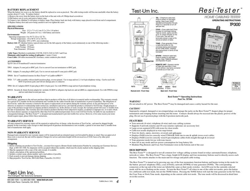
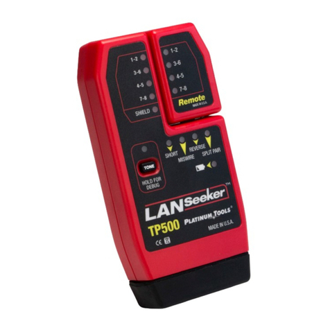
The PROFINET Cable Tester runs in 4-modes. The mode is selected with 4 buttons.
The cable tester is switched ON by pressing any of these buttons and it immediately starts testing in
the mode which is pressed. An LCD icon for the currently selected mode will be blinking.
Press any button except the selected mode button to switch the cable tester OFF.
Fig. 1 - Location of the buttons and Remote Unit

PROFINET Cable Tester – User Manual
_______________________________________________
Version 1.2.1 – June 2014 Page 9 / 32
PN1-Manual-EN.docx © PROCENTEC 2014 - Copyright - all rights reserved
Fig. 2 - LCD layout
2.1 PROFINET/Ethernet test mode (DATA/SEL Button)
In this mode the cable tester uses the RJ 45 Jack on the main unit and the “Remote Unit” to test a
cable.
The cable tester can switch between;
4 wires / 2-pairs (DATA2 mode)
PROFINET and other Industrial Ethernet networks with shielded cable.
8 wires / 4-pairs (DATA1 mode)
Regular Ethernet or 1Gbps Industrial Ethernet cable.
Press DATA/SEL for 2 seconds to switch between DATA1 and DATA2 mode.
The tester declares pins 1-2, 3-6, (4-5 and 7-8) as pairs and displays the “Pass” icon when all pins are
correctly wired in a one-to-one order. If the 1-2 and 3-6 pairs are crossed, the “Pass” icon will be
displayed along with a blinking “Uplink” icon. Uplink cables are also known as cross cables. For
shielded cable (PROFINET), the remote ID will flash alternately with “S” to indicate presence of
shielding.
2.2 Tone generator (TONE button)
The tone mode generates audio tones for use with tone tracers on selected pins.
The signal generated on a pair has the positive signal on one pin and the complement of the signal on
the other pin of the pair, yielding a nominal 10 volts peak-to-peak across the pair.
The pin number of the pin or the letters “P” (for pin) and “S”(for shield) being driven with tone and the
currently selected tone pattern is displayed on the screen along with the “Tone” icon and the icon for
the connector assumed to be used.
The TONE button steps to the next connector pin(s) drive option when pressed less than 2
seconds.

PROFINET Cable Tester – User Manual
_______________________________________________
Version 1.2.1 – June 2014 Page 10 / 32
PN1-Manual-EN.docx © PROCENTEC 2014 - Copyright - all rights reserved
When the TONE button is pressed and held down for longer than 2 seconds, another tone pattern
is selected until the button is released. The tone pattern options are Hi, Lo, HiLo1 and HiLo2. The HiLo
options are dual or warble tones of differing pattern duration.
Pressing any button other than TONE, switches OFF the cable tester. The tone will switch OFF
automatically after 2,4 hours.
2.3 Telephone test mode (VOICE button)
For this mode the cable tester uses the 6-position jack on the main unit and the remote unit to test a
cable. This mode uses the 3-pair USOC standard to define the pairs. Connector pins 1-6, 2-5 and 3-4
are the pairs defined by this standard. The tester will display the “Pass” icon when all 6 pins are
correctly wired in a one-to-one order.
If all 6 pins are correctly wired in the reverse order, the “Pass” icon along with a blinking “Rev” icon will
be displayed. Standard telephone cables used between a phone set and a wall jack are usually
reverse-pinned.
2.4 Coax test mode (VIDEO button)
The cable tester can test wire breaks and short circuits.
2.5 Split pair test
The cable tester has the ability to switch OFF the split pair test. Pressing the button for the current
cable test mode for more than 3 seconds, switches OFF the split pair testing. The “Split” icon and its
current state (ON or OFF) appear on the screen momentarily to indicate this. The split pair testing will
resume the next time the tester is switched ON, or can be toggled by another 3 second press of the
current test mode button.
2.6 Voltage detection
The cable tester monitors for voltage being present on the jacks during each test cycle. If voltage is
found, the “Volts!” icon is displayed and testing stops until the voltage is removed.
2.7 Battery replacement
When the battery low icon is ON, the battery should be replaced as soon as possible. The cable test
results will become unreliable when the battery reaches 4, 5 V. To replace the battery:
Remove the screw from the battery door on the back of the unit.
Pull the battery out of the cavity and remove the battery link.
Connect a new Alkaline 9 V battery to the battery link. Insert the battery back in the compartment
with the battery link placed towards the front-end.
Close the battery door and do NOT over tighten the screw.

PROFINET Cable Tester – User Manual
_______________________________________________
Version 1.2.1 – June 2014 Page 11 / 32
PN1-Manual-EN.docx © PROCENTEC 2014 - Copyright - all rights reserved
3 Testing PROFINET / Ethernet cable
BEFORE TESTING STARTS, INSPECT THE PLUGS OF THE CABLE.
Improperly crimped or damaged plugs can harm the jacks of the cable tester. Do NOT use 6-pin
(phone) plugs with the 8-pin RJ 45 jack.
Take out the Remote Unit of the main unit (squeeze remote at finger grip openings in main
unit to remove it).
Fig. 3 - Taking out the Remote Unit
The Remote Unit has to be placed on the other side of the cable. If the cable is short or both ends are
very close to each other, the Remote Unit can be left in the main unit.

PROFINET Cable Tester – User Manual
_______________________________________________
Version 1.2.1 – June 2014 Page 12 / 32
PN1-Manual-EN.docx © PROCENTEC 2014 - Copyright - all rights reserved
Plug one end of the cable into main unit and the other end of cable into the remote unit.
If PROFINET cable is tested, switch the split pair test OFF!!!
Press the DATA/SEL button for 3 seconds to switch split pair OFF (every time the button is pressed
for 3 seconds, split pair operation is toggled). By default the cable tester is set to split pair is ON!
To start testing press the DATA/SEL button.
Press DATA/SEL for 2 seconds to switch between DATA1: 8 wires (4 pairs) testing and DATA2: 4
wires (2 pairs) testing. By default the cable tester is set to DATA2!
Results are invalid if a cable is attached during a test in progress!
To switch the cable tester OFF, press the VIDEO button.
Fig. 4 - Cable attached to the Main and Remote Unit

PROFINET Cable Tester – User Manual
_______________________________________________
Version 1.2.1 – June 2014 Page 13 / 32
PN1-Manual-EN.docx © PROCENTEC 2014 - Copyright - all rights reserved
3.1 Interpreting PROFINET test results
Upon completion of a cable test, the wire map
display, ID and any faults are displayed.
- The top line pin numbers on the display
represent the connector pins on the main unit.
- The second line pin numbers represent the
connector pin numbers of the remote, normally
being the same as the top line for a one-to-one
wired cable.
The Pass icon will be ON if the cable has all
pins properly connected. The Fail, Short, Open
or Split icon will be on if there is a wiring error.
The wire map will display the end-to-end
connections measured whenever possible.
The Pass icon will also be on with a blinking
Uplink icon if a network cable has the 1-2 and
the 3-6 pairs transposed to indicate a properly
wired uplink/cross cable.
It is very important to check the
Shield icon if PROFINET or other Industrial
Ethernet cable is tested. IT SHOULD BE ON.
If there are multiple errors to display, there will
be a combination of the above error displays.
The ID icon will have a number directly to the
right of it, indicating the remote ID number
detected from the remote. A new test is in
progress whenever the “Voice” or “Data” icons
are ON.
If a split pair is detected, the detected pins and the “Split” icon will be blinking.

PROFINET Cable Tester – User Manual
_______________________________________________
Version 1.2.1 – June 2014 Page 14 / 32
PN1-Manual-EN.docx © PROCENTEC 2014 - Copyright - all rights reserved
3.1.1 Correct wiring (with Shield)
3.1.2 Correct wiring (without Shield)
When the shield has a break or is NOT connected, the Shield icon is NOT lit. This cable
seems to pass, but for PROFINET and other Industrial Ethernet systems, this cable should NOT be
approved!
3.1.3 Wire break
If a wire break is detected, the affected pins will be blank and the “Open” icon will be ON (blinking).

PROFINET Cable Tester – User Manual
_______________________________________________
Version 1.2.1 – June 2014 Page 15 / 32
PN1-Manual-EN.docx © PROCENTEC 2014 - Copyright - all rights reserved
3.1.4 Short circuit
If a short circuit is detected, the second line will have a ‘-’ in those positions along and the “Short” icon
will be ON (blinking).
3.1.5 Miswire
If a miswire is detected, the pin numbers will indicate the involved pin numbers and the “Miswire” icon
will be ON (blinking).

PROFINET Cable Tester – User Manual
_______________________________________________
Version 1.2.1 – June 2014 Page 16 / 32
PN1-Manual-EN.docx © PROCENTEC 2014 - Copyright - all rights reserved
4 Testing other cable
4.1 Testing Video/Coax Cable
Attach one end of coax cable to be tested to F-connector on main unit.
Remove remote unit from main unit by squeezing the remote lightly between the thumb and
forefinger through the openings provided in the main unit and pull it out of the main unit and attach
it to the other end of the cable to be tested.
Press the VIDEO button to switch ON the unit and begin testing. The results are updated once a
second.
To switch the cable tester OFF, press the VOICE or DATA button.
4.2 Testing Telephone cable
This is the same procedure as Ethernet cable.
The Rev icon will flash if all connected pins are in reverse order and the Pass icon will also be ON if all
6 connections are present. Telephone modular plug cables used between the wall jack and a phone
set are usually reverse pinned.
4.3 Placing a tone on a cable
Connect the cable to be traced to a main unit jack. For the best signal, do NOT connect a remote
to the other end. Due to the shielding effect of twisted pairs, the strongest signal is obtained by
having one wire of a pair carry tone. Selecting a single pin instead of a pair will do this. For video
coax cable, the Tone is best applied to the shield and the shield should NOT be additionally
grounded.
Switch ON the cable tester by pressing the button associated with the connector to be used
followed by pressing the TONE button. Short presses of the TONE button will select a different
pin. Holding down the TONE button for more than 2 seconds will select a different tone pattern.
To switch the cable tester OFF, press any button except TONE.
The tone will switch OFF automatically after 2,4 hours.

PROFINET Cable Tester – User Manual
_______________________________________________
Version 1.2.1 – June 2014 Page 17 / 32
PN1-Manual-EN.docx © PROCENTEC 2014 - Copyright - all rights reserved
5 Training
This chapter contains an exercise to enhance the practical knowledge of the PROFINET Cable Tester.
Try to recreate the schematic of a “Fault Box” below. It consists of six 2-channel switches which
generate faults in the wiring.
When the box is completed hit each switch and fill-out the fault table below.
S1 S2 S3 S4 S5 S6
1 or 2 = X
SH = X
1 = SH
2 = 3 3 = 2
2 or 6 = X
OK
1 = 6
SH = 1
1 = 3
3 = 1 1 = 3
3 or 6 = X
SH
WH
OG
YE
BU

PROFINET Cable Tester – User Manual
_______________________________________________
Version 1.2.1 – June 2014 Page 18 / 32
PN1-Manual-EN.docx © PROCENTEC 2014 - Copyright - all rights reserved
6 Technical Data
Dimensions and weight
Dimensions L x W x H (mm) with DB9
Weight
13,2 × 7,3 × 4,1 cm (5,2 × 2,9 × 1,6 inches)
242 g (8,5 oz.) with battery and Remote Unit
Ambient conditions
Operating temperature
Storage temperature
Humidity:
Isolation class
0 to 50 °C (32 to 122 °F)
-10 to 60 °C (14 to 140 °F)
10 % to 90 %, non-condensing
IP 20 (DIN 40 050)
Power supply and operating hours
Battery
Standby
Cable testing
Tone generator
Auto power OFF
9 V Alkaline battery
2,5 years
150 hours
250 hours
After 9 minutes the last button was pressed in cable
testing modes and after 2,4 hours in tone mode
Ethernet Test
Cable types
Pair resistance to pass test
Shield resistance to pass test
Cable length for split pair test
Data network cable, CAT6, CAT-5E, CAT-5, CAT-4, CAT-
3
Maximum 200 Ohm
Maximum 100 Ohm
Minimum 2 m cable for testing of split pairs
Coax Test
Resistance
Maximum 100 Ohm DC resistance, conductor plus shield
Other manuals for PROFINET
1
Table of contents
Other Procentec Cable Tester manuals
