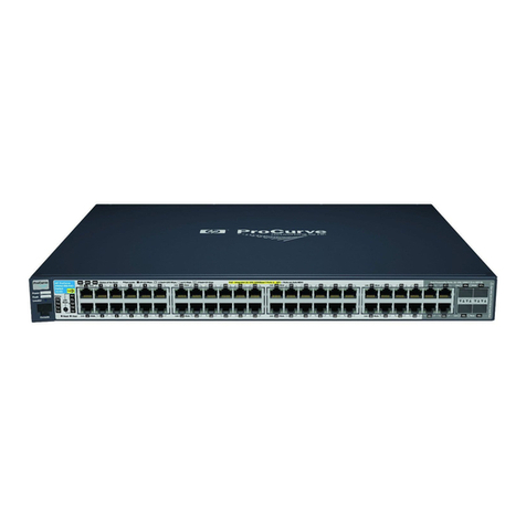
ProCurve 9408sl User manual

Less Work, More Network
http://www.procurve.com
Read Me First
for the ProCurve Routing Switch 9408sl
Covering Software Release 02.1.00c (July 2005)
The ProCurve 9408sl Routing Switch exceeds 100 lbs. (44 kg) without
modules and power supplies installed. To avoid personal injury, re-
duce weight of chassis by removing all modules and power supplies
from chassis prior to lifting or moving.
When handling, two or more people are required.
Contents:
■Important! Required Fan Threshold Settings . . . . . 1
■Software Updates Are Free! . . . . . . . . . . . . . . . . . . . 2
■Downloading Switch Software and Documentation
from the Web. . . . . . . . . . . . . . . . . . . . . . . . . . . . . . . . . 3
■Updating Software . . . . . . . . . . . . . . . . . . . . . . . . . . . 3
■Product Documentation Set. . . . . . . . . . 11
■Powering Up a Device Having Multiple
Power Supplies . . . . . . . . . . . . . . . . . . . . 13
■Included Components. . . . . . . . . . . . . . . 14
Important! Required Fan Threshold Settings
Users Must Change SFM Defaults in 02.1.00c
Although software version 02.1.00c corrected the default fan temperature thresholds for interface modules, it did not
correct the values for the Switch Fabric Module (SFM). Users are advised to modify the SFM fan temperature
thresholds and to save that setting in the config file. HP recommends the same thresholds for the SFM that are now
recommended (and are now defaults) for the interface modules. Use these commands to apply and save the new
recommended SFM fan temperature thresholds:
ProCurveRS(config)# fan-threshold switch-fabric low 50 med 46 55 med-hi 51 60 hi 56 85
ProCurveRS(config)# write mem

2
Explanation: Figure 1 below shows the recommended fan temperature thresholds, and visually demonstrates the
relationship between one speed's high threshold and the next higher speed's low threshold. (Some of the default
SFM thresholds in 02.1.00c violate the rule that the low temperature threshold of a higher fan speed must be lower
than the high temperature threshold of the lower fan speed.)
Figure 1 Fan temperature thresholds in the 9408sl
Software Updates Are Free!
Help Us Help You...Register Now To Keep Up-To-Date on the Latest
Software!
Hewlett-Packard periodically provides free software updates on the ProCurve website for various,
managed ProCurve networking products you may have in your network. To access the latest
software updates, go to the ProCurve website at http://www.procurve.com, then click on Software
updates to go to the ProCurve Networking software updates page.
Register for Automatic Notification of Updates. From the free software updates page you can
also register to automatically receive email notice of new updates for your managed ProCurve networking products.
Just follow the instructions on that page for how to receive the update notices.
To determine whether you have the latest software, compare the software version that is available on the website
with the version that is currently installed in the management module(s) in your routing switch.
HP periodically updates the software and documentation for your routing switch products. Refer to “Downloading
Switch Software and Documentation from the Web” on page 3.

3
Downloading Switch Software and Documentation from the Web
To Download a Software Version:
1. Go to the ProCurve website at http://www.procurve.com
2. Click on Software updates.
3. Under latest software, click on switches.
To Download Product Documentation: You will need the Adobe® Acrobat® Reader to view, print, and/or copy the
product documentation. You can download the latest version from Adobe at http://www.adobe.com.
1. Go to the ProCurve website at http://www.procurve.com
2. Click on Technical Support, then Product manuals.
3. Click on the name of the switch product for which you want documentation. (For a module, click on the name
of the switch product with which it is used.)
4. On the resulting web page, double-click on a document you want.
5. When the document file opens, click on the disk icon in the Acrobat toolbar and save a copy of the file.
Updating Software
This section explains how to upgrade the following software images on the management and interface modules:
• Monitor
• Boot
• ProCurve Software
• Field-Programmable Gate Array (FPGA) (interface modules only)
The sequence for a complete system upgrade is:
A. Upgrade the management module’s monitor and boot images
B. Upgrade the management module’s ProCurve software image
C. Upgrade the interface module’s monitor and boot images
D. Upgrade the interface module’s ProCurve software image
E. Upgrade the interface module’s FPGA images
F. Reboot using the boot system command
A. Upgrading the Management Module’s Monitor and Boot Images
Software releases 02.0.00a and later enable you to upgrade the management module’s monitor and boot images
simultaneously. Both images are contained in a single file, which is placed in both the boot flash and the code flash.
To upgrade the management module’s monitor and boot images simultaneously, perform the following steps:
1. Place the new monitor-and-boot-image file on a TFTP server to which the system has access or on a PCMCIA
flash card inserted in slot 1 or 2.

4
2. Copy the new monitor-and-boot-image file to the ProCurve 9408sl management module. Enter one of the
following commands at the Privileged EXEC level of the CLI:
For software version 02.1.00c, the "image-name" filename is "mb02100c.bin".
3. Verify that the new monitor and boot images have been successfully copied to flash by using the show flash
command. Check for the boot image, monitor image, and the date and time at which the new images were built.
B. Upgrading the Management Module’s ProCurve Software Image
To upgrade the management module’s ProCurve software image (primary or secondary), perform the following steps:
1. Place the new ProCurve software image on a TFTP server to which the ProCurve 9408sl system has access
or on a PCMCIA flash card inserted in slot 1 or 2.
2. Copy the new ProCurve software image from the TFTP server or a flash card in slot 1 or 2 to the management
module’s code flash. To perform this step, enter one of the following commands at the Privileged EXEC level
of the CLI:
•copy tftp flash <ip-addr> <image-name> primary | secondary
•copy slot1 | slot2 flash <image-name> primary | secondary
For software version 02.1.00c, the "image-name" filename is "mpr02100c.bin".
3. Verify that the new ProCurve software image has been successfully copied to the specified destination by using
the show flash command. Check for the primary or secondary image ("Application Image") and the time that
the image was built.
C. Upgrading the Interface Module’s Monitor and Boot Images
Software releases 02.0.00a and later enable you to upgrade an interface module’s monitor and boot images
simultaneously. Both images are contained in a single file, which is placed in both the boot flash and the code flash.
To upgrade an interface module’s monitor and boot images simultaneously, perform the following steps:
1. Place the new monitor-and-boot-image file on a TFTP server to which the system has access or on a PCMCIA
flash card inserted in slot 1 or 2.
Table 1: New Command Syntax for Upgrading Monitor and Boot Images
on the Management Module
Command Syntaxa
a.These commands are supported in software releases 02.0.00 and later.
Description
copy tftp flash <ip-addr> <image-name> mon copy-boot Copies the "image-name" file from a
TFTP server at "ip-addr" to both the
monitor file in code flash and the
boot file in boot flash.
copy slot1 | slot2 flash <image-name> mon copy-boot Copies the "image-name" file from a
flash card in slot 1 or 2 to both the
monitor file in code flash and the
boot file in boot flash.

5
2. Copy the new monitor-and-boot-image file to the interface module(s). Enter one of the following commands at
the Privileged EXEC level of the CLI:
For software version 02.1.00c, the "image-name" filename is "lb02100c.bin".
Note: If you copy the new monitor-and-boot image to all interface modules using the all keyword, the management
module makes a copy of the image (called lp-monitor-0) and stores it in its code flash. If you copy the new monitor-
and-boot image to a specified chassis slot, the management module does not make a copy of the image.
3. Verify that the new monitor and boot images were successfully copied to flash by using the show flash
command. Check for the monitor image, boot image, and the date and time at which the new images were built.
D. Upgrading the Interface Module’s ProCurve Software Image
To upgrade the ProCurve software image (primary or secondary) on all interface modules or an interface module in
a specified chassis slot, perform the following steps:
1. Place the new ProCurve software image on a TFTP server to which the system has access or on a PCMCIA
flash card inserted in slot 1 or 2.
2. Copy the new ProCurve software image from the TFTP server or a flash card in slot 1 or 2 to all interface
modules or an interface module in a specified chassis slot. To perform this step, enter one of the following
commands at the Privileged EXEC level of the CLI:
•copy tftp lp <ip-addr> <image-name> primary | secondary all | <chassis-slot-number>
•copy slot1 | slot2 lp <image-name> primary | secondary all | <chassis-slot-number>
For software version 02.1.00c, the "image-name" filename is "lp02100c.bin".
Table 2: New Command Syntax for Upgrading the Monitor and Boot Images
on the Interface Module
Command Syntaxa
a.These commands are supported in software releases 02.0.00 and later.
Description
copy tftp lp <ip-addr> <image-name> monitor copy-boot all | <slot-number> Copies the "image-
name" file from a TFTP
server at "ip-addr" to all
interface modules or to
the specified interface
module (slot-number),
placing it as both the
monitor file in code
flash and the boot file in
boot flash.
copy slot1 | slot2 lp <image-name> monitor copy-boot all | <slot-number> Copies the "image-
name" file from a flash
card in slot 1 or 2 to all
interface modules or to
the specified interface
module (slot-number),
placing it as both the
monitor file in code
flash and the boot file in
boot flash.

6
Note: If you copy the new ProCurve software image to all interface modules using the all keyword, the management
module makes a copy of the image (called lp-primary-0 or lp-secondary-0) and stores it in its code flash. If you copy
the new ProCurve software image to a specified chassis slot, the management module does not make a copy of the
image.
3. Verify that the new ProCurve software image has been successfully copied by entering the following command
at any level of the CLI:
show flash
Check for the ProCurve software image ("Application Image") and the date and time at which the image was built.
E. Upgrading an FPGA for a Gigabit Ethernet Module
The Gigabit Ethernet modules contain the following upgradable field-programmable gate array (FPGA) images:
• PBIF
•XTM
• XPP
• XBRIDGE (60-port module only)
When you upgrade the ProCurve 9408sl software to release 02.1.00, it is important to upgrade all FPGA images to
version 02.1.00 at the same time.
Determining the FPGA Image Versions
Normally, the show flash output identifies the currently-installed images, and the show version output identifies
the currently-running images. However, the FPGA versions that are currently installed and currently running on an
interface module are not correctly displayed until the interface module is power-cycled! The power-cycle of the
interface modules is accomplished by one of these procedures:
• reboot the 9408sl using the boot system command
• power-cycle each interface module using the lp power-off <slot> and lp power-on <slot> commands
• physically power-cycle the 9408sl routing switch
If you are not sure if the interface modules were power-cycled since installing FPGA images, you may want to perform
one of the listed procedures now. After that, you can use the show flash and show version commands to determine
the FPGA versions currently installed and currently running on the interface modules.
Note: Not all FPGA versions are necessarily updated with each new software release for the ProCurve 9408sl routing
switch. Also, FPGA versions are not necessarily the same for all interface modules. HP indicates the set of FPGA
files applicable for each software release by appending the software version to the filename. For example, filename
xpp02100c.bin has the XPP images for all interface modules for software version 02.1.00c, which installs these XPP
versions for these interface modules:
Module XPP Version
4-port 10-GbE Ver 88.6
40-port Mini-GBIC Ver 91.8
40-port 10/100/1000-T Ver 91.8
60-port 10/100/1000-T Ver 91.8
Upgrading the FPGA Images
To upgrade the FPGA images on a Gigabit Ethernet module, perform the following steps:
1. Place the new FPGA image(s) on a TFTP server to which the system has access or on a PCMCIA flash card
inserted in slot 1 or 2.

7
2. Copy the PBIF image from the TFTP server or a flash card in slot 1 or 2 to all interface modules or an interface
module in a specified chassis slot. To perform this step, enter one of the following commands at the Privileged
EXEC level of the CLI:
•copy tftp lp <ip-addr> <image-name> fpga-pbif all [<module-type>]
•copy tftp lp <ip-addr> <image-name> fpga-pbif <chassis-slot-number>
•copy slot1 | slot2 lp <image-name> fpga-pbif all [<module-type>]
•copy slot1 | slot2 lp <image-name> fpga-pbif <chassis-slot-number>
If you specify the module-type (e.g., 4x10g), the ProCurve 9408sl copies the PBIF images for that particular
module only. If you specify all without a module-type, the system copies the appropriate PBIF images to their
corresponding modules.
For software version 02.1.00c, the "image-name" filename is "pbif02100c.bin".
3. Copy the XTM image from the TFTP server or a flash card in slot 1 or 2 to all interface modules or an interface
module in a specified chassis slot. To perform this step, enter one of the following commands at the Privileged
EXEC level of the CLI:
•copy tftp lp <ip-addr> <image-name> fpga-xtm all
•copy tftp lp <ip-addr> <image-name> fpga-xtm <chassis-slot-number>
•copy slot1 | slot2 lp <image-name> fpga-xtm all
•copy slot1 | slot2 lp <image-name> fpga-xtm <chassis-slot-number>
For the XTM image, there is no option to specify "module-type".
For software version 02.1.00c, the "image-name" filename is "xtm02100c.bin".
4. Copy the XPP image from the TFTP server or a flash card in slot 1 or 2 to all interface modules or an interface
module in a specified chassis slot. To perform this step, enter one of the following commands at the Privileged
EXEC level of the CLI:
•copy tftp lp <ip-addr> <image-name> fpga-xpp all [<module-type>]
•copy tftp lp <ip-addr> <image-name> fpga-xpp <chassis-slot-number>
•copy slot1 | slot2 lp <image-name> fpga-xpp all [<module-type>]
•copy slot1 | slot2 lp <image-name> fpga-xpp <chassis-slot-number>
If you specify the module-type (e.g., 4x10g), the ProCurve 9408sl copies the XPP images for that particular
module only. If you specify all without a module-type, the ProCurve 9408sl copies the appropriate XPP images
to their corresponding modules.
For software version 02.1.00c, the "image-name" filename is "xpp02100c.bin".
5. Copy the XBRIDGE image from the TFTP server or a flash card in slot 1 or 2 to all interface modules or an
interface module in a specified chassis slot. To perform this step, enter one of the following commands at the
Privileged EXEC level of the CLI:
•copy tftp lp <ip-addr> <image-name> fpga-xbridge all [<module-type>]
•copy tftp lp <ip-addr> <image-name> fpga-xbridge <chassis-slot-number>
•copy slot1 | slot2 lp <image-name> fpga-xbridge all [<module-type>]
•copy slot1 | slot2 lp <image-name> fpga-xbridge <chassis-slot-number>
If you specify the module-type (e.g., 1gx60-gc-v6), the ProCurve 9408sl copies the xbridge images for that
particular module only. If you specify all without a module-type, the ProCurve 9408sl copies the appropriate
xbridge images to their corresponding modules.
For software version 02.1.00c, the "image-name" filename is "xbridge02100c.bin".
F. Rebooting the Management Module
After upgrading the software images on the management and interface modules, you must reboot the management
module. After the management module reboots, it in turn reboots the interface modules.

8
Furthermore, each interface module must be power-cycled in order for the new FPGA images to be loaded. Therefore,
you must reboot the system using the boot system command (not the reload command). Use this command to
reboot the management module, specifying primary or secondary to correspond with where you placed the new
software images:
•boot system flash primary | secondary
During the management module reboot, the following synchronization events occur:
• If you have a standby management module, the active management module compares the standby
module’s monitor, primary, and secondary images to its own. If you have updated these images on the
active module, the active module automatically synchronizes the standby module’s images with its own.
• If you copied the primary and/or secondary ProCurve software image and/or monitor-and-boot image
to all interface modules using the copy command with the all keyword, the management module made
a copy of the image and stored it in its code flash under the names lp-primary-0, lp-secondary-0 or lp-
monitor-0. By default, the system checks the interface modules’ ProCurve software images, which reside
in the code flash of the interface modules and the management module to make sure they are the same
in both locations. (The interface module images are retained on the management module for storage
only, and are not run by the management or interface modules.) If the images stored on the interface
and management modules are different, the system automatically enters "interactive mode" and prompts
you to do the following:
– If you want to update the ProCurve software images in the interface module’s code flash with the
images in the management module’s code flash, enter the lp cont-boot sync <slot-number> | all
command at the Privileged EXEC prompt.
– If you want to retain the ProCurve software images in the interface module’s code flash, enter the
lp cont-boot no-sync <slot-number> | all command at the Privileged EXEC prompt.
Note: If you do not enter a command within 60 seconds, the synchronization proceeds automatically.
After the management module finishes booting, do the following:
• Enter the show module command at any CLI level, and verify that the status of all interface modules
is CARD_STATE_UP.
• Enter the show version command at any CLI level, and verify that all management and interface
modules are running the new software image version.
If you find that an interface module is in a waiting state or is running an older software image, then you may have
forgotten to enter the lp cont-boot sync <slot-number> command at the Privileged EXEC prompt.
Downloading a New Image Using a Script
With software version 02.1.00c, you can create a script to download new software images to your ProCurve 9408sl.
Use this command to download an image using a script:
syntax: copy tftp system <ip_addr> <download_script>
The <ip_addr> variable is used to identify the IP address of the tftp server that holds the script.
The <download_script> variable is the name of the script containing download specifications.
The CLI command first copies the download script specified to the system's memory. It then parses the script to
perform the software download specified in the script.
The following section describes the download script syntax.
# download script syntax:
# <spec_line>
# ...
# <spec_line>
# where <spec_line> == KEYWORD:<val>;
#

9
# 1) Supported KEYWORD
# SRC // specify source of the images, optional
# DIR // image source directory, optional
# MP_MON // MP monitor image
# MP_APP // MP application image
# LP_MON // LP monitor image
# LP_APP // LP application image
# XPP // FPGA XPP
# XTM // FPGA XTM
# PBIF // FPGA PBIF
# XBRIDGE // FPGA XBRIDGE
# Note: If SRC is not specified, the images are taken from the server specified in the CLI
command line.
#
# 2) Syntax of <val>
#
# It depends on the KEYWORD preceding it:
#
# SRC:tftp:<ip_addr>;
#
# MP_MON:<image_name>:[boot]; // [boot] is the option to copy monitor to boot.
# MP_APP:pri:<image_name>;
# MP_APP:sec:<image_name>;
#
# LP_MON:all:<image_name>:[boot];
# LP_MON:<slot#>[[,-]<slot#>]:<image_name>:[boot];
#
# LP_APP:pri:all:<image_name>;
# LP_APP:pri:<slot#>[[,-]<slot#>]:<image_name>;
# LP_APP:sec:all:<image_name>;
# LP_APP:sec:<slot#>[[,-]<slot#>]:<image_name>;
#
# XPP:all:<image_name>;
# XPP:<slot#>[[,-]<slot#>]:<image_name>;
#
# XTM:all:<image_name>;
# XTM:<slot#>[[,-]<slot#>]:<image_name>;
#
# PBIF:all:<image_name>;
# PBIF:<slot#>[[,-]<slot#>]:<image_name>;
#
# XBRIDGE:all:<image_name>;
# XBRIDGE:<slot#>[[,-]<slot#>]:<image_name>;
#
# Note: If one <spec_line> fails to parse, or it fails to copy, the script is aborted.
Sample Install Script
The following example script installs software files on a ProCurve 9408sl using files previously stored on a TFTP
server.
The script must be stored in the same directory as the image files. Be sure to change the script to match your needs,
as noted in the script comments.
The script installs all files from the source area as follows:
1. Install file mb02100c.bin to MP in both the monitor area, and also boot flash.

10
2. Install file mpr02100c.bin to MP primary flash.
3. Install file lb02100c.bin to all LPs in both the monitor area, and also boot flash.
4. Install file lp02100c.bin to all LPs in the primary flash area.
5. Install FPGA file pbif02100c.bin to all LPs.
6. Install FPGA file xtm02100c.bin to all LPs.
7. Install FPGA file xpp02100c.bin to all LPs.
8. Install FPGA file xbridge02100c.bin to all LPs (error messages will indicate the slots that do not have 60-
port modules, and therefore do not need or accept the XBRIDGE image).
After the script completes, use the show flash command to verify successful transfer of boot image, monitor image,
and primary software image. (There is no command to verify successful FPGA file transfer until after the interface
modules have been power-cycled.)
Then use this command to reboot the management module (which will cause a power-cycle of the interface modules),
specifying primary to correspond with where the script placed the new software images:
• boot system flash primary
# Filename: 9408sl-Script-02100c-TFTP.txt
#
# Sample 9408sl install script for 02.1.00c.
#
# This version uses TFTP to install these
# images: boot-and-monitor, pri flash, FPGAs.
#
# CHANGES NEEDED TO USE THIS:
# 1) change IP address to be your TFTP server
#
# NOTES:
# i. Script must be stored in
# same directory as image files.
# ii. If any line fails, script aborts!
# Users MUST verify results!
# iii. After files are installed, 9408sl must be
# rebooted for the upgrade to take effect.
#
# SYNTAX:
# copy tftp system <ip-addr> <script-filename>
#
SRC:tftp:10.10.10.56;
MP_MON:mb02100c.bin:boot;
MP_APP:pri:mpr02100c.bin;
LP_MON:all:lb02100c.bin:boot;
LP_APP:pri:all:lp02100c.bin;
PBIF:all:pbif02100c.bin;
XTM:all:xtm02100c.bin;
XPP:all:xpp02100c.bin;
XBRIDGE:all:xbridge02100c.bin;

11
Product Documentation Set
Note: HP periodically updates the ProCurve 9300/9400 Series Routing Switch documentation. For the latest version
of any of these publications, visit the ProCurve website at:
http://www.procurve.com
Click on Technical Support, then Product manuals.
Read Me First
The "Read Me First" document, printed on bright yellow paper, is included with every chassis and module. It contains
an overview of software release information, an included parts list, and other information that is not included
elsewhere in the product documentation. It also includes:
• software update instructions
• operating notes for this release
Installation and Basic Configuration Guide for the ProCurve 9300 Series Routing Switches
This is an electronic (PDF) guide containing product safety and EMC regulatory statements as well as installation
and basic configuration information, and software and hardware specifications. This guide is included on the
Documentation CD shipped with your HP product. The latest version is also available on the ProCurve website.
Topics Specific to the 9300 Series Routing Switches
• Product mounting instructions
• Module installation
• Basic access and connectivity configuration (passwords, IP addresses)
• Redundant management module commands and file systems
• Cooling system commands and information
• Basic software feature configuration (SNMP, clock, mirror/monitor ports)
• Configuring for these features:
– Uni-Directional Link Detection (UDLD)
– Metro Ring Protocol (MRP)
– Virtual Switch Redundancy Protocol (VSRP)
– GVRP (dynamic VLANs)
• Software update instructions
• Hardware specs
• Software specs (e.g. RFC support, IEEE compliance)
Topics Covered for the 9300/9408sl Routing Switches
• Port settings
•VLANS
• Trunks
• Spanning Tree Protocol
•Syslog
Quick Start Guide for the ProCurve Series 9300 Routing Switches
This is a printed guide you can use as an easy reference to the installation and product safety information needed
for out-of-box setup, plus the general product safety and EMC regulatory statements of which you should be aware
when installing and using a Routing Switch. This guide is on the Documentation CD shipped with your HP product,
and the latest version is also available on the ProCurve web site.

12
Installation and Basic Configuration Guide for the ProCurve 9408sl Routing Switch
This is a printed guide that describes the ProCurve 9408sl and provides procedures for installing modules and AC
power supplies into the ProCurve 9408sl, cabling the 10 Gigabit Ethernet interface ports, and performing a basic
configuration of the software. The guide explains how to perform tasks using the CLI.
Topics Specific to the 9408sl Routing Switch
• Product overview and architecture
• Product mounting instructions
• Module installation
• Basic access and connectivity configuration (passwords, IP addresses)
• Management Module redundancy and file systems
• Interacting with the cooling system, switch fabric module, and interface modules
• Basic software feature configuration (SNMP, clock, mirror/monitor ports)
• Hardware maintenance instructions
• Software update instructions
• Hardware specs
• Safety and regulatory statements
• Software specs (e.g. RFC support, IEEE compliance)
Advanced Configuration and Management Guide for the ProCurve 9300/9400 Series
Routing Switches
This is an electronic (PDF) guide that contains advanced configuration information for routing protocols and Quality
of Service (QoS). In addition, appendixes in this guide contain reference information for network monitoring, policies,
and filters. This guide is included on the Documentation CD shipped with your HP product. The latest version is also
on the ProCurve website.
Information on Configuring Features
• Quality of Service (QoS)
• Access Control Lists (ACLs)
• Rate limiting
•IPv4routing
•RIP
•IPMulticast
• OSPF
•BGP4
• Mulitcast BGP (MBGP)
• Network Address Translation (NAT)
• VRRP and VRRPE (enhanced VRRP)
• IPX routing
• AppleTalk routing
• Rout health injection
• Standby Routing Protocol (SRP)
• RMON, Netflow, and Sflow monitoring
IPv6 Configuration Guide for the ProCurve Routing Switches
This is an electronic (PDF) guide that describes the IPv6 software and features. It provides conceptual information
about IPv6 addressing and explains how to configure basic IPv6 connectivity and the IPv6 routing protocols. The
software procedures explain how to perform tasks using the CLI. This reference is included on the Documentation
CD shipped with your HP product and is also available on the ProCurve website.

13
Command Line Interface Reference for ProCurve 9300/9400 Series Routing Switches
This is an electronic (PDF) guide that provides a dictionary of CLI commands and syntax. This reference is included
on the Documentation CD shipped with your HP product and is also available on the ProCurve website.
Security Guide for the ProCurve 9300/9400 Series Routing Switches
This is an electronic (PDF) guide that provides procedures for securing management access to HP devices and for
protecting against Denial of Service (DoS) attacks. This guide is included on the Documentation CD shipped with
your HP product. The latest version is also available on the ProCurve website.
Diagnostic Guide for the ProCurve 9300/9400 Series Routing Switches
This is an electronic (PDF) guide that describes the diagnostic commands available on HP devices. The software
procedures show how to perform tasks using the Command Line Interface (CLI). This guide is included on the
Documentation CD shipped with your HP product.The latest version is also available on the ProCurve website.
Removing and Installing XENPAK Optics
This is a printed instruction sheet describing the correct preparation and procedure for removing and installing
XENPAK optics on the J8174A 2-port 10 Gigabit Ethernet module. This sheet is shipped with the Procurve 9300M
Management modules and is also available on both the Documentation CD shipped with your HP product and on
the ProCurve website.
Release Notes
These documents describe features and other information that becomes available between revisions of the main
product guides. New releases of such documents will be available on HP's ProCurve website. To register to receive
email notice from HP when a new software release is available, visit:
http://www.procurve.com
Click on My software, and then click on Register Here.
Product Documentation CD: A Tool for Finding Specific Information and/or Printing
Selected Pages
This CD is shipped with your HP Routing Switch product and provides the following:
•AREADME file describing the CD contents and use, including easy instructions on how to search the
book files for specific information
•AContents file to give you easy access to the documentation on the CD
• Separate PDF files of the individual chapters and appendixes in the major guides, enabling you to easily
print individual chapters, appendixes, and selected pages
• Single PDF files for each of the major guides, enabling you to use the Adobe® Acrobat® Reader to
easily search for detailed information
• Additional files. These may include such items as additional Read Me files and release notes.
Powering-Up a Device Having Multiple Power Supplies
When you power-up a device that requires multiple power supplies, make sure you apply power to all the supplies
(or at least to the minimum number of supplies required for your configuration) at the same time. Otherwise, the
device either will not boot at all, or will boot and then repeatedly display a warning message stating that you need
to add more power supplies.

14
Included Components
Component Notes
Power Cords ProCurve 9408sl: Three power cords.
Caution: If the installation requires a different power cord than the one supplied with the switch or routing switch,
be sure to use a shielded power cord displaying the mark of the safety agency that defines the regulations for
power cords in your country. The mark is your assurance that the power cord can be used safely with the switch
or routing switch.
Console Cable Connects a terminal or PC to a serial port on a ProCurve 9408sl management module for direct-connect access
to management using the Command Line Interface (CLI).
CESD Grounding Tap Kit Use the Cable Electrostatic Discharge (CESD) Grounding Tap before connecting Category 5 or better UTP copper
networking cables to the routing switch. Refer to the documentation provided with the kit.
ESD Strap Helps to prevent electrostatic discharge between your body and routing switch modules or chassis.
Rack Mount Kit Contains two mounting brackets and the screws required to attach the brackets to the routing switch.
Product Documentation • Read Me First (this document): Updates are periodically posted on the ProCurve website.*
• Installation and Basic Configuration Guide for the ProCurve 9408sl Routing Switch.
Installation Guide for
XENPAK Optics
This single-sheet guide is included in the documentation set shipped with all ProCurve 9408sl modules.
Warranty and Support Included with routing switch chassis shipments.
Declaration of Conformity Included with routing switch chassis shipments.
* Go to http://www.procurve.com, click on Technical Support, then Product manuals. Click on ProCurve Routing Switch 9400 Series and
scroll to the publication you want to see.

15
-- The page left blank intentionally--

Techncial information in this document is subject
to change without notice.
© Copyright 2005 Hewlett-Packard
Development Company, L.P. All rights reserved.
Reproduction, adaptation, or translation without
prior written permision is prohibited except as
allowed under the copyright laws.
July 2005
Manual Part Number
5092-1797
Printed in USA
*5092-1797*
Table of contents
Other ProCurve Switch manuals
ProCurve
ProCurve 2610 Series User manual
ProCurve
ProCurve 9304m Setup guide
ProCurve
ProCurve ProCurve 1800-8G User manual

ProCurve
ProCurve ProCurve 1800-8G User manual

ProCurve
ProCurve zl Series User manual
ProCurve
ProCurve Series 8100fl Manual
ProCurve
ProCurve 6200yl Series User manual
ProCurve
ProCurve 2600 Series User manual
ProCurve
ProCurve 2610 Series User manual

ProCurve
ProCurve 2610 Series User manual
