N-3299-22958
(2014/11)
3299-22958
CZ Infrapasivní snímačpohybu vysílací
GB Passive Infrared Transmitting Switch
ABB s.r.o.
Elektro-Praga
Resslova 3
466 02 Jablonec n. N. Tel.: +420 483 364 111
Czech Republic Hotline: +420 800 800 104
http://www.abb.cz/elektropraga E-mail: epj.jablonec@cz.abb.com
CZ
POPIS FUNKCE
Přístroj slouží ve spolupráci s přijímači systému RF 868®
k dálkovému bezdrátovému ovládání elektrických spotře-
bičů (svítidel). Infrapasivní snímačpřijímá záření v infra-
červené části spektra, které je pro lidské oko neviditelné.
Zaregistruje-li snímačzměnu, kterou vyvolá např. pohyb
osoby v oblasti dosahu (obr. 1), dojde k vyslání kódova-
ného radiofrekvenčního (RF) signálu.
Snímačpracuje ve dvou režimech:
ON/OFF – snímačvysílá nejprve signál pro zapnutí. Po
uběhnutí nastavené časové prodlevy vyšle signál pro vy-
pnutí.
ON – snímačvysílá pouze signál pro zapnutí. Vypnutí za-
jistí funkce časovač, předem nastavená na přijímači.
Svítivá dioda (LED) umístěná pod čočkou infrapasivního
snímače indikuje vysílání a v případěvybité baterie
upozorňuje na potřebu její výměny krátkým
problikáváním.
Upozornění:
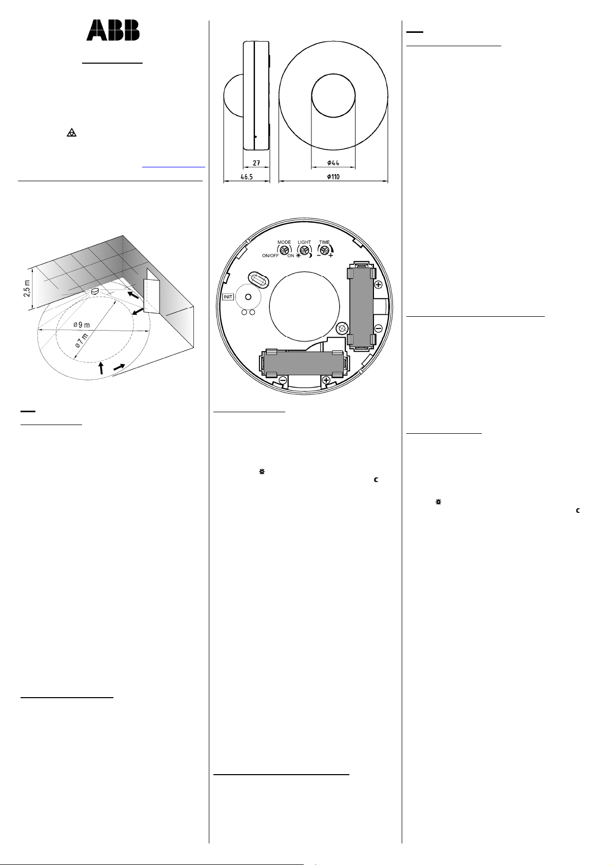
Velikost zóny, ve které infrapasivní snímačreaguje na
pohyb osob, závisí v případěstropní montáže především
na výšce umístění snímače. Kromětoho je velikost zóny
ovlivněna mnoha dalšími okolnostmi, jako je rychlost a
směr pohybu vzhledem ke snímači, teplota okolí,
přítomnost rušivých zdrojůtepla (topná tělesa, osvětlení
apod.). Informativní zóna dosahu v závislosti na směru
pohybu vzhledem k orientaci snímače je znázorněna na
obr. 1 (výška snímače nad podlahou je 2,5 m). Při
montáži do větší výšky se zóna dosahu úměrnězvětšuje
(až asi Ø16 m při výšce montáže 8 m).
MONTÁŽ A NASTAVENÍ
Infrapasivní snímač(obr. 2) je určen pro montáž na strop
buďpřímo, nebo na instalační krabici. Pootočením víčka
proti směru pohybu hodinových ruček se víčko sejme a
snímačse přišroubuje pomocí dvou šroubůvložených do
otvorůve snímači (rozteč60 mm) podle obr. 3.
Do snímače se vloží dvěbaterie – pozor na správnou po-
laritu!
Po ukončení nastavování a zápisu snímače do paměti
přijímače se víčko na snímačznovu nasadí a zajistí
pootočením ve směru pohybu hodinových ruček. Víčko se
může proti sejmutí pojistit zašroubováním dodávaného
šroubku 2,2×4 do otvoru mezi hranu víčka a pláště.
Nastavovací prvky
Na zadní straněsnímače jsou tři nastavovací prvky:
a) LIGHT (hladina okolního osvětlení)
Snímačreaguje na pohyb, je-li úroveňosvětlení v místě
instalace nižší než nastavená hodnota. Při vyšší úrovni
okolního osvětlení je přístroj deaktivován (signál se nevy-
sílá ani v případědetekce pohybu). Při nastavení do levé
krajní polohy ( ) přístroj signál pro zapnutí vysílá praktic-
ky za jakéhokoliv osvětlení, v pravé krajní poloze ( ) vysí-
lá pouze za tmy.
b) TIME (zpoždění vypnutí / potlačení vysílání)
V režimu ON/OFF se tímto nastavovacím prvkem nasta-
vuje zpoždění vypnutí, což je doba, po kterou bude svíti-
dlo zapnuto od okamžiku ukončení detekce pohybu. Do-
bu lze nastavit od asi 20 sekund do 30 minut. Poloha ve
středu rozsahu odpovídá asi 5 minutám.
V režimu ON se zpoždění vypnutí nastavuje na přijímači,
který musí být ve funkci časovač. Nastavovacím prvkem
na snímači se ve třech hodnotách nastavuje potlačení vy-
sílání, což je minimální doba mezi dvěma vysíláními sig-
nálu pro zapnutí při trvalém pohybu před snímačem.
V krajní poloze „–“ je nastavena hodnota 1 minuta, upro-
střed 5 minut a v krajní poloze „+“ 15 minut.
c) Nastavení režimu MODE
Funkce je z výroby nastavena na režim ON/OFF. Pokud
potřebujete změnit režim na ON, otočte nastavovací pr-
vek do označené krajní polohy.
Upozornění:
Doba potlačení vysílání by měla odpovídat minimálně
polovinědoby zpoždění nastavené na časovači přijímače.
To znamená, že např. pro dobu potlačení 1 min je vhodné
nastavení časovače na přijímači od 2 do 5 minut apod.
Změna v nastavení zpoždění vypnutí / potlačení vysílání
se projeví až po uplynutí původněnastavené doby nebo
okamžitěpo stisku vysílacího tlačítka INIT (obr. 3)!
Z důvodu dosažení maximální životnosti baterie je třeba
co nejvíce omezit počet vysílání. Proto je vhodné, pokud
to konkrétní provozní podmínky pro použití snímačů
umožňují, nenastavovat zbytečně krátkou dobu zpoždění
vypnutí v režimu ON/OFF a stejnětak nenastavovat
nejkratší dobu potlačení vysílání v režimu ON.
Zápis snímače do paměti přijímače
- Na přijímači nastavte požadovanou funkci (viz manuál
příslušného přijímače) podle režimu snímače –
ON/OFF pro režim snímačeON/OFF nebo časovačpro
režim snímačeON.
- Pro odvysílání kódu potřebného pro zápis do paměti
přijímače krátce stiskněte při zacloněné čočce vysílací
tlačítko INIT na snímači (obr. 3). Vysílání kódu je indi-
kováno blikáním LED pod čočkou snímače.
GB
OPERATING PRINCIPLE
Use this device along with receivers of the RF 868®
system for remote wireless control of electrical appliances
(luminaires). The PIR switch picks up invisible infrared
radiation. If it detects a change caused e.g. by the
movement of a person in the detection zone (fig. 1), a
coded radio-frequency (RF) signal is transmitted.
The PIR switch works in two modes:
ON/OFF - first, the switch transmits the ON signal. Once
the switch-off delay expires, it transmits the OFF signal.
ON - the switch transmits the ON signal only. The timer
function (preset on the receiver) will switch off the
appliance.
The light-emitting diode (LED) located under the lens of
the passive infrared switch indicates transmitting. Fast
flashing indicates a low battery.
Note:
The size of the area covered by a ceiling-mounted PIR
switch depends mainly on its installation height. In
general, the size of the movement detection zone is
affected by numerous other factors, too, e.g. speed and
direction of the person‘s movement with respect to the
switch, ambient temperature, or the presence of
interfering heat sources (heaters, lighting, etc.). The
informative detection zone depending on the movement
direction with reference to the switch orientation is
specified in fig. 1 (installation height of 2.5 m). If the
installation height is greater, the detection zone expands
proportionately (up to dia. 16 m at an installation height of
8 m).
INSTALLATION AND ADJUSTMENT
The passive infrared switch (fig. 2) is designed for direct
installation on the ceiling or an installation box. Turn the
cover counter clockwise to remove it and attach the
switch, using two screws in holes of the switch (pitch of
60 mm) as shown in fig. 3.
Insert two batteries in the switch - pay attention to correct
polarity!
Once adjustment and programming of the switch in the
memory is complete, re-attach the cover and lock it by
turning it clockwise. To secure the cover against removal,
you can lock it by screwing the supplied 2.2×4 screw into
the hole between the cover edge and the case.
Adjusting elements
There are three adjusting elements on the rear side:
a) LIGHT (response threshold)
The switch responses to movement if the illumination
level in the installation location is lower than the set value.
If the level of ambient illumination is higher, the device will
be deactivated (the signal will not be transmited even in
case of movement detection). If set to the left limit
position ( ), the device will transmit the ON signal in any
level of illumination, while in the right limit position ( ), it
will transmit only when it is dark.
b) TIME (switch-off delay/suppression of transmitting)
Use this adjustment in the ON/OFF mode to set the
switch-off delay, i.e. the duration of the ON status of the
luminary from the time of the last movement detection. A
period between 20 seconds and 30 minutes can be set.
The middle position represents a period of approximately
5 minutes.
In the ON mode, the switch-off delay is set on the
receiver, which must be set to the timer function. The
adjusting element on the switch is used to set
transmission suppression in three values. Transmission
suppression means the minimum period between two
switch-on signal transmissions in case of continual
movements in the detection zone of the switch. The "-"
limit position represents 1 minute, the middle position
5 minutes and the "+" limit position 15 minutes.
c) MODE setting
The factory setting of the function is the ON/OFF mode. If
you need to change the mode to ON, turn the adjustment
element to the marked limit position.
Note:
The duration of transmission suppression should
correspond to at least half of the switch-off delay period
set on the receiver timer. This means that for suppression
of a transmitting time of 1 minute, it is desirable to set the
receiver timer from 2 to 5 minutes, etc.
Change in setting of switch-off delay / suppression of
transmitting will be applied only after the previously set
time is pased or immediately after pressing the INIT
transmission button (fig. 3)!
In order to achieve maximum battery life, the number of
transmissions must be minimized. Therefore, it is better (if
the specific operating conditions permit it) not to set an
unnecessarily short switch-off delay in ON/OFF mode and
identicaly not to set the shortest duration of transmission
suppression in the ON mode.
Obr. 2
Obr. 1 Obr. 3


