PROEL M822USB User manual

M822USB
8-CH 4-BUS MIXER
WITH FX AND USB
USER MANUAL
MANUALE D'USO
BENUTZERHANDBUCH
NOTICE D'UTILISATION
MANUAL DE USO
ﻡﺍﺩﺧﺗﺳﻻﺍ ﻝﻳﻟﺩ

FCC COMPLIANCE NOTICE
This device complies with part 15 of the FCC rules. Operaon is subject to the following two condions:
(1) This device may not cause harmful interference, and
(2) this device must accept any interference received, including interference that may cause undesired operaon.
CAUTION: Changes or modificaons not expressly approved by the party responsible for compliance could void
the user’s authority to operate the equipment.
NOTE: This equipment has been tested and found to comply with the limits for a Class B digital device, pursuant to
part 15 of the FCC Rules. These limits are designed to provide reasonable protecon against harmful interference in
a residenal installaon. This equipment generates, uses, and can radiate radio frequency energy and, if not installed
and used in accordance with the instrucon manual, may cause harmful interference to radio communicaons.
However, there is no guarantee that interference will not occur in a parcular installaon. If this equipment does
cause harmful interference to radio or television recepon, which can be determined by turning the equipment off
and on, the user is encouraged to try to correct the interference by one or more of the following measures:
• Reorient or relocate the receiving antenna.
• Increase the separaon between the equipment and receiver.
• Connect the equipment into an outlet on a circuit different from that to which the receiver is connected.
• Consult the dealer or an experienced radio/TV technician for help.
This marking shown on the product or its literature, indicates that it should not be disposed with other household wastes at the end of
its working life. To prevent possible harm to the environment or human health from uncontrolled waste disposal, please separate this
from other types of wastes and recycle it responsibly to promote the sustainable reuse of material resources. Household users should
contact either the retailer where they purchased this product, or their local government office, for details of where and how they can
take this item for environmentally safe recycling. Business users should contact their supplier and check the terms and condions of the
purchase contract. This product should not be mixed with other commercial wastes for disposal.
The lightning flash with arrowhead symbol within an equilateral triangle is intended to alert the user to the presence of uninsulated
“dangerous voltage” within the product’s enclosure, that may be of sufficient magnitude to constute a risk of electric shock to persons.
The exclamaon point within an equilateral triangle is intended to alert the user to the presence of important operang and maintenance
(servicing) instrucons in the literature accompanying the appliance.
The informaon contained in this publicaon has been carefully prepared and checked. However no responsibility will be taken for any errors. All
rights are reserved and this document cannot be copied, photocopied or reproduced in part or completely without wrien consent being obtained
in advance from PROEL. PROEL reserves the right to make any aesthec, funconal or design modificaon to any of its products without any prior
noce. PROEL assumes no responsibility for the use or applicaon of the products or circuits described herein.
Il marchio riportato sul prodoo o sulla documentazione indica che il prodoo non deve essere smalto con altri rifiudomesci al
termine del ciclo di vita. Per evitare eventuali danni all’ambiente si invita l’utente a separare questo prodoo da altri pi di rifiue di
riciclarlo in maniera responsabile per favorire il riulizzo sostenibile delle risorse materiali. Gli utendomesci sono invitaa contaare
il rivenditore presso il quale è stato acquistato il prodoo o l’ufficio locale preposto per tue le informazioni relave alla raccolta
differenziata e al riciclaggio per questo po di prodoo. Gli uten
aziendali sono invitaa contaare il proprio fornitore e verificare i
termini e le condizioni del contrao di acquisto. Questo prodoo non deve essere smalto unitamente ad altri rifiucommerciali.
Il simbolo del lampo con freccia in un triangolo equilatero intende avverre l'ulizzatore per la presenza di "tensioni pericolose" non isolate
all'interno dell'involucro del prodoo, che possono avere una intensità sufficiente a costuire rischio di scossa elerica alle persone.
Il punto esclamavo in un triangolo equilatero intende avverre l'ulizzatore per la presenza di importanistruzioni per l'ulizzo e la
manutenzione nella documentazione che accompagna il prodoo.
Le informazioni contenute in questo documento sono state aentamente redae e controllate. Tuavia non è assunta alcuna responsabilità per
eventuali inesaezze. Tui dirisono riservae questo documento non può essere copiato, fotocopiato, riprodoo per intero o in parte senza
previo consenso scrio della PROEL. PROEL si riserva il dirio di apportare senza preavviso cambiamene modifiche esteche, funzionali o di
design a ciascun proprio prodoo. PROEL non assume alcuna responsabilità sull’uso o sul l’applicazione dei prodoo dei circuiqui descri.

Das Kennzeichen auf dem Gerät oder den beiliegenden Unterlagen zeigt an, dass das Gerät am Ende seiner Lebensdauer nicht im
Hausmüll entsorgt werden darf. Aus Umweltschutzgründen bien wir den Anwender, das Gerät von anderem Müll getrennt zu entsorgen
und dem Recycling zuzuführen, damit die Rohstoffe umweltverträglich wiederverwertet werden können. Private Anwender wenden sich
dazu bie an den Händler, bei dem sie das Produkt gekauhaben, oder an eine örtliche Behörde, die Informaonen zur Mülltrennung
und zum Recycling dieser Art von Geräten geben kann. Gewerbliche Anwender werden gebeten, sich an den Zulieferer zu wenden und
die Vertragsbedingungen des Kaufvertrags zu überprüfen. Das Gerät darf nicht zusammen mit anderem Gewerbemüll entsorgt werden.
Das Symbol mit einem Pfeilblitz in einem gleichseigen Dreieck warnt den Anwender vor „gefährlicher Spannung“ ohne Isolierung im
Gehäuse des Geräts. Diese kann hoch genug sein, um Stromschlaggefahr zu verursachen.
Das Ausrufezeichen in einem gleichseigen Dreieck weist den Anwender auf wichge Anweisungen zum Gebrauch und zur Instandhaltung
des Geräts in den beiligenden Unterlagen hin.
Die Angaben in diesem Dokument wurden sorgfälg zusammengestellt und kontrolliert. Für mögliche Ungenauigkeiten übernehmen wir dennoch
keine Haung. Alle Rechte vorbehalten. Das Dokument darf ohne vorherige schriliche Genehmigung von PROEL nicht ganz oder in Teilen kopiert
oder reproduziert werden. PROEL behält sich das Recht vor, ohne Vorankündigung Änderungen an der Gestaltung, an den Funkonen oder
am Design aller ihrer Produkte vorzunehmen. PROEL haet nicht für den Gebrauch oder die Verwendung der hier beschriebenen Geräte oder
elektrischen Systeme.
La marque reportée sur le produit ou sur la documentaon indique que l'appareil ne doit pas être éliminé avec d'autres déchets domesques au
terme du cycle de sa vie. Afin d'éviter tout dommage à l'environnement, l'ulisateur est invité à séparer cet appareil des autres types de déchets
et de le recycler de manière responsable pour favoriser la réulisaon durable des ressources matérielles. Les ulisateurs domesques sont invités
à contacter le revendeur où l'appareil a été acheté ou le service local préposé afin d'obtenir toutes les informaons relaves au tri sélecf et au
recyclage pour ce type de produit. Les ulisateurs des entreprises sont invités à contacter leur fournisseur et à vérifier les termes et les condions
du contrat d'achat. Cet appareil ne doit pas être éliminé avec d'autres déchets commerciaux.
Le symbole d'un éclair avec une flèche dans un triangle équilatéral est desné à averr l'ulisateur de la présence de « tensions dangereuses » non
isolées dans le boîer de l'appareil, lesquelles peuvent avoir une intensité suffisante pour constuer un risque de choc électrique pour les personnes.
Le point d'exclamaon dans un triangle équilatéral est desné à averr l'ulisateur de la présence d'instrucons importantes en vue de l'ulisaon
et de la maintenance de l'appareil dans la documentaon qui l'accompagne.
Les informaons contenues dans ce document ont été rédigées avec aenon et contrôlées. Toutefois, la société PROEL n'assume aucune responsabilité
en cas d'inexactude. Tous les droits sont réservés et ce document ne peut être copié, photocopié, reproduit en ener ou en pare, sans avoir obtenu au
préalable le consentement écrit de la société PROEL. PROEL se réserve le droit d'apporter, sans préavis, des changements et des modificaons esthéques,
fonconnelles ou de design à tous ses produits. PROEL n'assume aucune responsabilité quant à l'ulisaon ou l'applicaon des appareils ou des circuits
décrits dans cee noce.
La marca reproducida en el producto o en la documentación indica que el producto no se debe eliminar con otros desechos doméscos al final de su
ciclo de vida úl. Para evitar posibles daños al medio ambiente se invita al usuario a separar este producto de otros pos de desechos y reciclarlo de
forma responsable para favorecer el uso sostenible de los recursos materiales. Los usuarios doméscos deben ponerse en contacto con el revendedor
donde han comprado el producto o la oficina local encargada, para conocer todas las informaciones correspondientes a la recogida selecva y al
reciclaje para este po de producto. Se invita a las empresas a ponerse en contacto con su proveedor y controlar los términos y las condiciones del
contrato de compra. Este producto no se debe eliminar junto con otros desechos comerciales.
El símbolo del relámpago con flecha en un triángulo equilátero ene la intención de adverr al usuario respecto a la presencia de "tensiones peligrosas"
no aisladas dentro de la envoltura del producto, que pueden tener una intensidad suficiente para constuir riesgo de descarga eléctrica a las personas.
El punto exclamavo en un triángulo equilátero ene la intención de adverr al usuario respecto a la presencia de importantes instrucciones para el
uso y el mantenimiento en la documentación que acompaña el producto.
Las informaciones contenidas en este documento se han redactado y controlado atentamente. Sin embargo, el fabricante se exime de toda responsabilidad
por posibles inexactudes. Todos los derechos reservados; por tanto este documento no se puede copiar, fotocopiar, reproducir total o parcialmente sin la
autorización previa escrita por parte de PROEL. PROEL si reserva el derecho de realizar sin previo aviso cambios estécos, funcionales o de diseño a cualquier
producto suyo. PROEL no se asume ninguna responsabilidad por el uso o la aplicación de los productos o de los circuitos que se describen aquí.
ﻰﻠﻋ ﺭﺍﺭﺿﺃ ﺔﻳﺃ ﺏﻧﺟﺗﻟ .ﻲﺿﺍﺭﺗﻓﻻﺍ ﻩﺭﻣﻋ ﺔﻳﺎﻬﻧ ﻲﻓ ﻯﺭﺧﻷﺍ ﺔﻳﻟﺯﻧﻣﻟﺍ ﺕﺎﻳﺎﻔﻧﻟﺍ ﻊﻣ ﻪﻧﻣ ﺹﻠﺧﺗﻟﺍ ﻡﺗﻳ ﻻ ﻥﺃ ﺏﺟﻳ ﺞﺗﻧﻣﻟﺍ ﻥﺄﺑ ﻖﺋﺎﺛﻭﻟﺍ ﻰﻠﻋ ﻭﺃ ﺞﺗﻧﻣﻟﺍ ﻰﻠﻋ ﺓﺭﻭﻛﺫﻣﻟﺍ ﺔﻣﻼﻌﻟﺍ ﻝﺩﺗ
.ﺩﺍﻭﻣﻟﺍ ﺭﺩﺎﺻﻣﻟ ﺔﻣﺍﺩﺗﺳﻣﻟﺍ ﻡﺍﺩﺧﺗﺳﻻﺍ ﺓﺩﺎﻋﺇ ﻰﻠﻋ ﻊﻳﺟﺷﺗﻠﻟ ﺔﻟﻭﺅﺳﻣ ﺔﻘﻳﺭﻁﺑ ﻩﺭﻳﻭﺩﺗ ﺓﺩﺎﻋﺇﻭ ﺕﺎﻳﺎﻔﻧﻟﺍ ﻥﻣ ﻯﺭﺧﻷﺍ ﻉﺍﻭﻧﻷﺍ ﻥﻋ ﺞﺗﻧﻣﻟﺍ ﺍﺫﻫ ﻝﺻﻔﺑ ﻡﻭﻘﻳ ﻥﺃ ﻡﺩﺧﺗﺳﻣﻟﺍ ﻥﻣ ﻭﺟﺭﻧ ﺔﺋﻳﺑﻟﺍ
ﺓﺩﺎﻋﺇﻭ ﺕﺎﻳﺎﻔﻧﻠﻟ ﺯﻳﺎﻣﺗﻣﻟﺍ ﻊﻣﺟﻟﺎﺑ ﺔﻘﻠﻌﺗﻣﻟﺍ ﺕﺎﻣﻭﻠﻌﻣﻟﺍ ﻊﻳﻣﺟ ﻥﻋ ﻝﻭﺅﺳﻣﻟﺍ ﻲﻠﺣﻣﻟﺍ ﺏﺗﻛﻣﻟﺍ ﻭﺃ ﻪﻧﻣ ﺞﺗﻧﻣﻟﺍ ءﺍﺭﺷ ﻡﺗ ﻱﺫﻟﺍ ﺔﺋﺯﺟﺗﻟﺍ ﻊﺋﺎﺑﺑ ﺍﻭﻠﺻﺗﻳ ﻥﺃ ﻝﺯﺎﻧﻣﻟﺍ ﻲﻓ ﻥﻳﻣﺩﺧﺗﺳﻣﻟﺍ ﻥﻣ ﻭﺟﺭﻧ
ﻊﻣ ﺞﺗﻧﻣﻟﺍ ﺍﺫﻫ ﻥﻣ ﺹﻠﺧﺗﻟﺍ ﻡﺩﻋ ﺏﺟﻳ .ءﺍﺭﺷﻟﺍ ﺩﻘﻋ ﻁﻭﺭﺷﻭ ﺩﻭﻧﺑ ﻥﻣ ﻖﻘﺣﺗﻟﺍﻭ ﻡﻬﺗﺻﺎﺧ ﺩﺭﻭﻣﻟﺎﺑ ﺍﻭﻠﺻﺗﻳ ﻥﺃ ﺕﺎﻛﺭﺷﻟﺍ ﻲﻓ ﻥﻳﻣﺩﺧﺗﺳﻣﻟﺍ ﻥﻣ ﻭﺟﺭﻧ .ﺕﺎﺟﺗﻧﻣﻟﺍ ﻥﻣ ﻉﻭﻧﻟﺍ ﺍﺫﻫ ﺭﻳﻭﺩﺗ
.ﻯﺭﺧﻷﺍ ﺔﻳﺭﺎﺟﺗﻟﺍ ﺕﺎﻳﺎﻔﻧﻟﺍ
ﻝﻛﺷﻳﻟ ﺔﻳﻓﺎﻛ ﺓﻭﻘﺑ ﺩﻬﺟﻟﺍ ﺍﺫﻫ ﻥﻭﻛﻳ ﻥﺃ ﻥﻛﻣﻳﻭ ،ﺞﺗﻧﻣﻟﺍ ﺔﻳﻭﺎﺣ ﻝﺧﺍﺩ ﻝﻭﺯﻌﻣ ﺭﻳﻏ "ﺭﻳﻁﺧ ﺩﻬﺟ" ﺩﻭﺟﻭ ﻥﻣ ﻡﺩﺧﺗﺳﻣﻟﺍ ﺭﻳﺫﺣﺗ ﻲﻧﻌﻳ ﻉﻼﺿﻷﺍ ﻱﻭﺎﺳﺗﻣ ﺙﻠﺛﻣ ﻲﻓ ﻡﻬﺳﺑ ﻕﺭﺑﻟﺍ ﺯﻣﺭ ﻥﺇ
.ﺹﺎﺧﺷﻸﻟ ﺔﻳﺋﺎﺑﺭﻬﻛﻟﺍ ﺕﺎﻣﺩﺻﻟﺍ ﻲﻓ ﺏﺑﺳﺗﻠﻟ ﺍﺭﻁﺧ
.ﺞﺗﻧﻣﻟﺍ ﻊﻣ ﺔﻘﻓﺭﻣﻟﺍ ﻖﺋﺎﺛﻭﻟﺍ ﻲﻓ ﺔﻧﺎﻳﺻﻟﺍﻭ ﻡﺍﺩﺧﺗﺳﻼﻟ ﺔﻣﻬﻣ ﺕﺎﻣﻳﻠﻌﺗ ﺩﻭﺟﻭ ﻥﻣ ﻡﺩﺧﺗﺳﻣﻟﺍ ﺭﻳﺫﺣﺗ ﻉﻼﺿﻷﺍ ﻱﻭﺎﺳﺗﻣ ﺙﻠﺛﻣ ﻲﻓ ﺏﺟﻌﺗﻟﺍ ﺔﻣﻼﻋ ﻲﻧﻌﺗ
ﺭﻳﻭﺻﺗ ﻭﺃ ﺦﺳﻧ ﺯﻭﺟﻳ ﻻﻭ ،ﺔﻅﻭﻔﺣﻣ ﻕﻭﻘﺣﻟﺍ ﻊﻳﻣﺟ .ﺎﻬﻳﻓ ﺔﻗﺩﻠﻟ ﺹﻘﻧ ﻱﺃ ﻥﻋ ﺔﻳﻟﻭﺅﺳﻣ ﺔﻳﺃ ﺔﻛﺭﺷﻟﺍ ﻝﻣﺣﺗﺗ ﻻ ،ﻙﻟﺫ ﻊﻣﻭ .ﺔﻳﺎﻧﻌﺑ ﺎﻬﻧﻣ ﻖﻘﺣﺗﻟﺍﻭ ﺔﻘﻳﺛﻭﻟﺍ ﻩﺫﻫ ﻲﻓ ﺓﺩﺭﺍﻭﻟﺍ ﺕﺎﻣﻭﻠﻌﻣﻟﺍ ﺩﺍﺩﻋﺇ ﻡﺗ
ﻭﺃ ﺔﻳﻔﻳﻅﻭ ﻭﺃ ﺔﻳﻟﺎﻣﺟ ﺕﻼﻳﺩﻌﺗﻭ ﺕﺍﺭﻳﻳﻐﺗ ﺔﻳﺃ ءﺍﺭﺟﺇ ﻲﻓ ﻖﺣﻟﺎﺑ PROEL ﻅﻔﺗﺣﺗ .PROEL ﻥﻣ ﺏﻭﺗﻛﻣﻭ ﻖﺑﺳﻣ ﺢﻳﺭﺻﺗ ﻰﻠﻋ ﻝﻭﺻﺣﻟﺍ ﻥﻭﺩﺑ ﺎﻳﺋﺯﺟ ﻭﺃ ﺎﻳﻠﻛ ﺔﻘﻳﺛﻭﻟﺍ ﻩﺫﻫ ﺝﺎﺗﻧﺇ ﺓﺩﺎﻋﺇ ﻭﺃ
.ﺔﻘﻳﺛﻭﻟﺍ ﻩﺫﻫ ﻲﻓ ﺓﺭﻭﻛﺫﻣﻟﺍ ﺭﺋﺍﻭﺩﻟﺍ ﻭﺃ ﺕﺎﺟﺗﻧﻣﻟﺍ ﻝﺎﻣﻌﺗﺳﺍ ﻭﺃ ﻡﺍﺩﺧﺗﺳﺍ ﻥﻋ ﺔﻳﻟﻭﺅﺳﻣ ﺔﻳﺃ PROEL ﻝﻣﺣﺗﺗ ﻻ .ﻖﺑﺳﻣ ﺭﺍﺫﻧﺇ ﻥﻭﺩﺑ ﺎﻬﺗﺎﺟﺗﻧﻣ ﻥﻣ ﺞﺗﻧﻣ ﻱﺃ ﻰﻠﻋ ﺔﻳﻣﻳﻣﺻﺗ

4
INDEX
FCC COMPLIANCE NOTICE . . . . . . . . . . . . . . . . . . . . . . . 2
TECHNICAL SPECIFICATIONS . . . . . . . . . . . . . . . . . . . . . 4
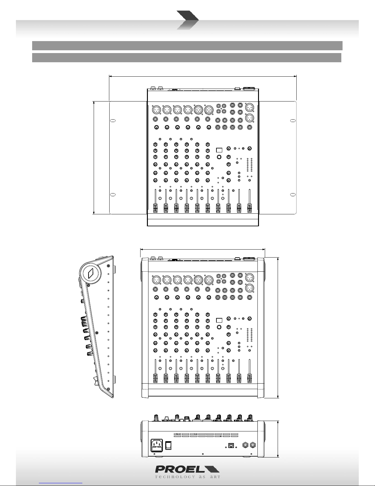
MECHANICAL DIMENSIONS . . . . . . . . . . . . . . . . . . . . . . 5
LAYOUT . . . . . . . . . . . . . . . . . . . . . . . . . . . . . . . . . . . . . . 6
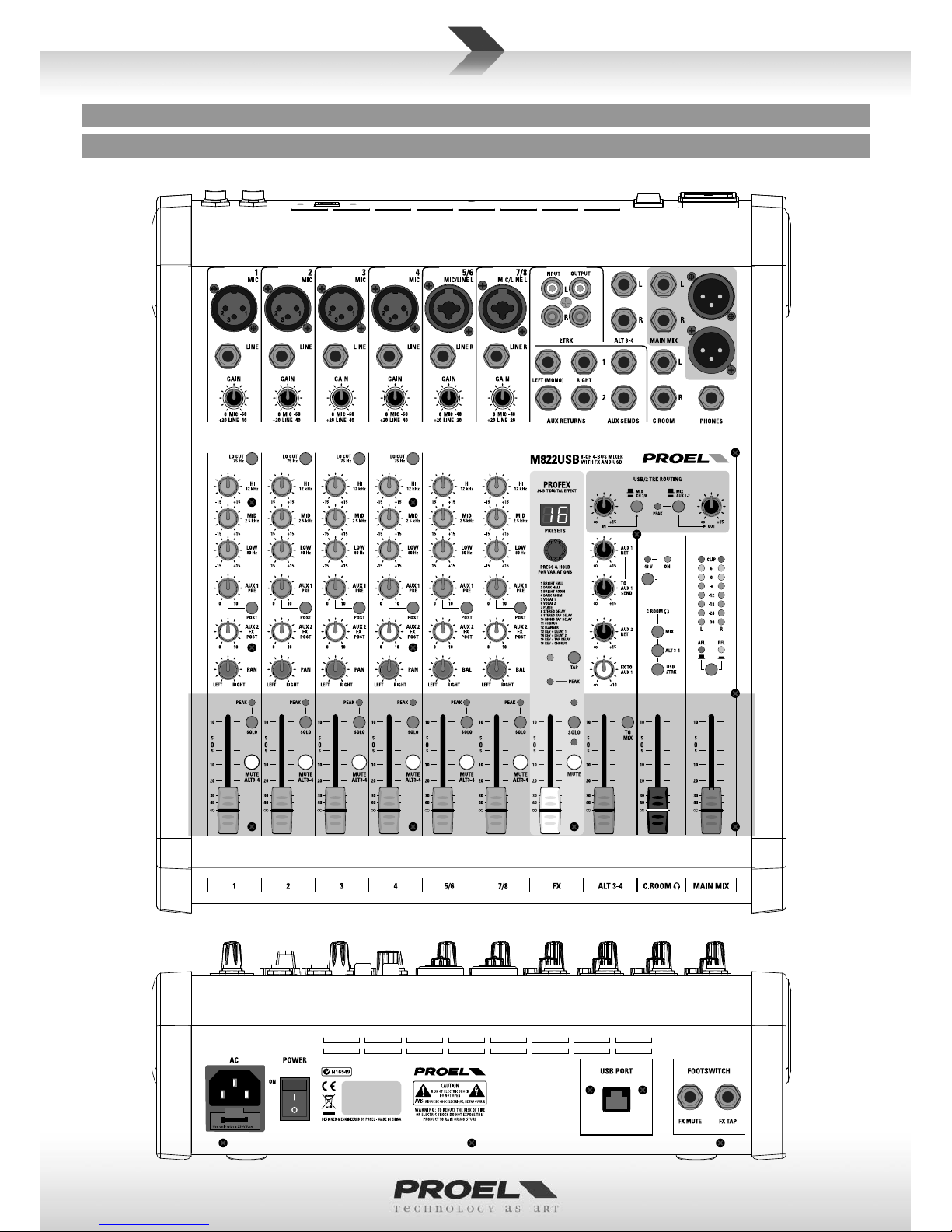
CONTROL PANEL (FIG.1). . . . . . . . . . . . . . . . . . . . . . . . . 7
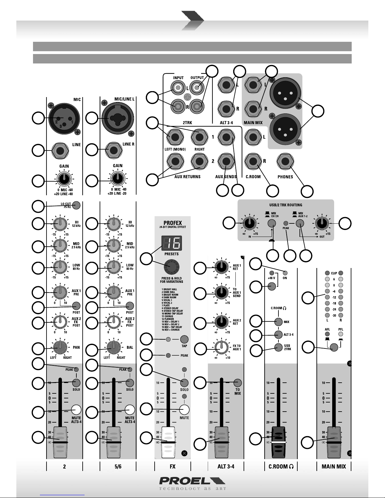
CONTROL PANEL (FIG.2). . . . . . . . . . . . . . . . . . . . . . . . . 8
CONNECTIONS . . . . . . . . . . . . . . . . . . . . . . . . . . . . . . . . 8
CONFIGURATION EXAMPLE . . . . . . . . . . . . . . . . . . . . . . 9
ENGLISH LANGUAGE. . . . . . . . . . . . . . . . . . . . . . . . . . . 10
SAFETY AND PRECAUTIONS . . . . . . . . . . . . . . . . . . . . . 10
IN CASE OF FAULT . . . . . . . . . . . . . . . . . . . . . . . . . . . . . 10
CE CONFORMITY. . . . . . . . . . . . . . . . . . . . . . . . . . . . . . 10
PACKAGING, SHIPPING AND COMPLAINT . . . . . . . . . . 10
WARRANTY AND PRODUCTS RETURN . . . . . . . . . . . . . 10
INSTALLATION AND DISCLAIMER . . . . . . . . . . . . . . . . . 10
POWER SUPPLY AND MAINTENANCE . . . . . . . . . . . . . 10
GENERAL INFORMATION . . . . . . . . . . . . . . . . . . . . . . . 11
OPERATING INSTRUCTIONS (FIG. 1 / 2). . . . . . . . . . . . 11
ÍNDICE
FCC COMPLIANCE NOTICE . . . . . . . . . . . . . . . . . . . . . . . 2
CARACTERÍSTICAS TÉCNICAS . . . . . . . . . . . . . . . . . . . . . 7
DIMENSIONES MECÁNICAS . . . . . . . . . . . . . . . . . . . . . . 8
LAY-OUT . . . . . . . . . . . . . . . . . . . . . . . . . . . . . . . . . . . . . 9
PANEL DE CONTROL (FIG.1) . . . . . . . . . . . . . . . . . . . . . 10
PANEL DE CONTROL (FIG.2) . . . . . . . . . . . . . . . . . . . . . 11
CONEXIONES. . . . . . . . . . . . . . . . . . . . . . . . . . . . . . . . . 11
EJEMPLO DE CONFIGURACION . . . . . . . . . . . . . . . . . . 12
IDIOMA ESPAÑOL . . . . . . . . . . . . . . . . . . . . . . . . . . . . . 41
ADVERTENCIAS PARA LA SEGURIDAD . . . . . . . . . . . . . 41
EN CASO DE AVERÍA . . . . . . . . . . . . . . . . . . . . . . . . . . . 41
CONFORMIDAD CE . . . . . . . . . . . . . . . . . . . . . . . . . . . . 41
EMBALAJE, TRANSPORTE Y RECLAMACIONES. . . . . . . 41
GARANTÍAS Y DEVOLUCIONES . . . . . . . . . . . . . . . . . . . 41
INSTALACIÓN Y LIMITACIONES DE USO . . . . . . . . . . . . 41
ALIMENTACIÓN Y MANTENIMIENTO . . . . . . . . . . . . . . 41
INFORMACIÓN GENERAL . . . . . . . . . . . . . . . . . . . . . . . 42
INSTRUCCIONES OPERATIVAS (FIG. 1 / 2) . . . . . . . . . . 42
INDICE
FCC COMPLIANCE NOTICE . . . . . . . . . . . . . . . . . . . . . . . 2
SPECIFICHE TECNICHE . . . . . . . . . . . . . . . . . . . . . . . . . . 4
DIMENSIONI MECCANICHE . . . . . . . . . . . . . . . . . . . . . . 5
LAY-OUT . . . . . . . . . . . . . . . . . . . . . . . . . . . . . . . . . . . . . 6
PANNELLO DI CONTROLLO (FIG.1) . . . . . . . . . . . . . . . . . 7
PANNELLO DI CONTROLLO (FIG.2) . . . . . . . . . . . . . . . . . 8
CONNESSIONI . . . . . . . . . . . . . . . . . . . . . . . . . . . . . . . . . 8
ESEMPIO CONFIGURAZIONE . . . . . . . . . . . . . . . . . . . . . 9
LINGUA ITALIANA . . . . . . . . . . . . . . . . . . . . . . . . . . . . . 17
AVVERTENZE PER LA SICUREZZA . . . . . . . . . . . . . . . . . 17
IN CASO DI GUASTO . . . . . . . . . . . . . . . . . . . . . . . . . . . 17
CONFORMITÀ CE. . . . . . . . . . . . . . . . . . . . . . . . . . . . . . 17
IMBALLAGGIO, TRASPORTO E RECLAMI . . . . . . . . . . . 17
GARANZIE E RESI . . . . . . . . . . . . . . . . . . . . . . . . . . . . . 17
INSTALLAZIONE E LIMITAZIONI D’USO. . . . . . . . . . . . . 17
ALIMENTAZIONE E MANUTENZIONE . . . . . . . . . . . . . . 17
INFORMAZIONI GENERALI . . . . . . . . . . . . . . . . . . . . . . 18
ISTRUZIONI OPERATIVE (FIG. 1 / 2) . . . . . . . . . . . . . . . 18
INDEX
FCC COMPLIANCE NOTICE . . . . . . . . . . . . . . . . . . . . . . . 2
SPÉCIFICATIONS TECHNIQUES . . . . . . . . . . . . . . . . . . . . 6
DIMENSIONS MÉCANIQUES. . . . . . . . . . . . . . . . . . . . . . 8
LAY-OUT . . . . . . . . . . . . . . . . . . . . . . . . . . . . . . . . . . . . . 9
PANNEAU DE COMMANDE (FIG.1). . . . . . . . . . . . . . . . 10
PANNEAU DE COMMANDE (FIG.2). . . . . . . . . . . . . . . . 11
CONNEXIONS . . . . . . . . . . . . . . . . . . . . . . . . . . . . . . . . 11
EXEMPLE DE CONFIGURATION. . . . . . . . . . . . . . . . . . . 12
LANGUE FRANÇAISE . . . . . . . . . . . . . . . . . . . . . . . . . . 34
MISES EN GARDE DE SÉCURITÉ . . . . . . . . . . . . . . . . . . 34
EN CAS DE PANNE. . . . . . . . . . . . . . . . . . . . . . . . . . . . . 34
CONFORMITÉ CE. . . . . . . . . . . . . . . . . . . . . . . . . . . . . . 34
EMBALLAGE, TRANSPORT ET RÉCLAMATIONS . . . . . . 34
GARANTIES ET RETOURS . . . . . . . . . . . . . . . . . . . . . . . 34
INSTALLATION ET LIMITES D'UTILISATION . . . . . . . . . . 34
ALIMENTATION ET MAINTENANCE . . . . . . . . . . . . . . . 34
INFORMATIONS GÉNÉRALES . . . . . . . . . . . . . . . . . . . . 35
INSTRUCTIONS DE FONCTIONNEMENT (FIG. 1 / 2) . . 35
ﺱﺭﻬﻔﻟﺍ
2 .................................... FCC COMPLIANCE NOTICE
7 ............................................................... ﺔﻳﻧﻘﺗﻟﺍ ﺕﺎﻔﺻﺍﻭﻣﻟﺍ
8 ................................................................ﺔﻳﻛﻳﻧﺎﻛﻳﻣﻟﺍ ﺩﺎﻌﺑﻷﺍ
9 .......................................................................... ﻡﻳﻣﺻﺗﻟﺍ
10 .......................................................(1 ﻝﻛﺷﻟﺍ) ﻡﻛﺣﺗﻟﺍ ﺔﺣﻭﻟ
11 .......................................................(2 ﻝﻛﺷﻟﺍ) ﻡﻛﺣﺗﻟﺍ ﺔﺣﻭﻟ
12 ................................................... ﺔﺋﻳﻬﺗﻟﺍ ﻭﺃ ﻥﻳﻭﻛﺗﻟﺍ ﻥﻋ ﻝﺎﺛﻣ
48 ..................................................................ﺔﻳﺑﺭﻌﻟﺍﺔﻳﺑﺭﻌﻟﺍ
48 ..................................................ﺔﻣﻼﺳﻟﺎﺑ ﺔﺻﺎﺧﻟﺍ ﺕﺍﺭﻳﺫﺣﺗﻟﺍ
48 .................................................................ﻝﻁﻌﻟﺍ ﺔﻟﺎﺣ ﻲﻓ
48 ....................................................................CE ﺔﻘﺑﺎﻁﻣ
48 ............................................ﻯﻭﺎﻛﺷﻟﺍﻭ ﻝﻘﻧﻟﺍﻭ ﻑﻳﻠﻐﺗﻟﺍﻭ ﺔﺋﺑﻌﺗﻟﺍ
48 ...............................................................ﺩﺋﺍﻭﻌﻟﺍﻭ ﻥﺎﻣﺿﻟﺍ
48 .............................................. ﻡﺍﺩﺧﺗﺳﻻﺍ ﻰﻠﻋ ﺩﻭﻳﻘﻟﺍﻭ ﺏﻳﻛﺭﺗﻟﺍ
48 ...............................................................ﺔﻧﺎﻳﺻﻟﺍﻭ ﺔﻳﺫﻐﺗﻟﺍ
49 .................................................................ﺔﻣﺎﻋ ﺕﺎﻣﻭﻠﻌﻣ
49 ............................................. (2 / 1 ﻝﻛﺷﻟﺍ) ﻝﻳﻐﺷﺗﻟﺍ ﺕﺎﻣﻳﻠﻌﺗ
INHALT
FCC COMPLIANCE NOTICE . . . . . . . . . . . . . . . . . . . . . . . 2
TECHNISCHE DATEN . . . . . . . . . . . . . . . . . . . . . . . . . . . . 6
MECHANISCHE ABMESSUNGEN. . . . . . . . . . . . . . . . . . . 8
LAYOUT . . . . . . . . . . . . . . . . . . . . . . . . . . . . . . . . . . . . . . 9
REGLER (ABB.1). . . . . . . . . . . . . . . . . . . . . . . . . . . . . . . 10
REGLER (ABB.2). . . . . . . . . . . . . . . . . . . . . . . . . . . . . . . 11
ANSCHLÜSSE. . . . . . . . . . . . . . . . . . . . . . . . . . . . . . . . . 11
KONFIGURATIONSBEISPIEL. . . . . . . . . . . . . . . . . . . . . . 12
DEUTSCHE SPRACHE. . . . . . . . . . . . . . . . . . . . . . . . . . . 27
SICHERHEITSHINWEISE. . . . . . . . . . . . . . . . . . . . . . . . . 27
BEI EINEM DEFEKT . . . . . . . . . . . . . . . . . . . . . . . . . . . . 27
EG-KONFORMITÄT. . . . . . . . . . . . . . . . . . . . . . . . . . . . . 27
VERPACKUNG, TRANSPORT UND REKLAMATIONEN . . 27
GARANTIE UND RÜCKGABE . . . . . . . . . . . . . . . . . . . . . 27
INSTALLATION UND VERWENDUNGSEINSCHRÄNKUNGEN
27
STROMVERSORGUNG UND INSTANDHALTUNG . . . . . 27
ALLGEMEINE INFORMATIONEN . . . . . . . . . . . . . . . . . . 28
GEBRAUCHSANLEITUNG (ABB. 1 / 2). . . . . . . . . . . . . . 28

5
MODEL M822USB Connectors MODELLO M822USB Conneori
MONO INPUT CHANNELS CANALI INGRESSO MONO
Mic Input Sensivity from 0 to -60 dBu Balanced XLR-F Sensibilità Ingresso Mic da 0 a -60 dBu XLR-F Bilanciato
Mic Input Impedance 2 Kohm Impedenza Ingresso Mic 2 Kohm
Line Input Sensivity from +20 to -40 dBu Balanced Jack Sensibilità Ingresso Line da +20 a -40 dBu Jack Bilanciato
Line Input Impedance 10 Kohm Impedenza Ingresso Line 10 Kohm
LO CUT 75Hz, 18dB/oct. FILTRO LO CUT 75Hz, 18dB/oct.
EQ HIGH (shelving) ±15 dB @ 12KHz EQ ALTI (shelving) ±15 dB @ 12KHz
EQ MID (peaking) ±15 dB @ 2.5KHz EQ MEDI (peaking) ±15 dB @ 2.5KHz
EQ LOW (shelving) ±15 dB @ 80Hz EQ BASSI (shelving) ±15 dB @ 80Hz
STEREO INPUT CHANNELS CANALI INGRESSO STEREO
Mic Input Sensivity from 0 to -40 dBu Balanced XLR-F Sensibilità Ingresso Mic da 0 a -40 dBu XLR-F Bilanciato
Mic Input Impedance 2 Kohm Impedenza Ingresso Mic 2 Kohm
Line Input Sensivity from +20 to -20 dBu Balanced Jack Sensibilità Ingresso Line da +20 a -20 dBu Jack Bilanciato
Line Input Impedance 10 Kohm Impedenza Ingresso Line 10 Kohm
EQ HIGH (shelving) ±15 dB @ 12KHz EQ ALTI (shelving) ±15 dB @ 12KHz
EQ MID (peaking) ±15 dB @ 2.5KHz EQ MEDI (peaking) ±15 dB @ 2.5KHz
EQ LOW (shelving) ±15 dB @ 80Hz EQ BASSI (shelving) ±15 dB @ 80Hz
MASTER SECTION SEZIONE MASTER
MAIN MIX nom. out level +4 dBu Balanced Jack / XLR-M Livello nom. MAIN MIX +4 dBu Jack Bilanciato / XLR-M
ALT 3-4 nom. out level 0 dBu Unbalanced Jack Livello nom. ALT 3-4 0 dBu Jack Sbilanciato
C.ROOM nom. out level 0 dBu Unbalanced Jack Livello nom. C.ROOM 0 dBu Jack Sbilanciato
AUX nom. out level 0 dBu Unbalanced Jack Livello nom. AUX 0 dBu Jack Sbilanciato
2 - TRK nom. out level 0 dBu Unbalanced Rca Livello nom. 2 - TRK OUT 0 dBu Rca Sbilanciato
2 - TRK nom. in level 0 dBu Unbalanced Rca Livello nom. 2 - TRK IN 0 dBu Rca Sbilanciato
PHONES min. impedance 32 ohm Stereo Jack Impedenza min. PHONES 32 ohm Jack Stereo
PHONES max. out level (2x) 193 mW Livello max. PHONES (2x) 193 mW
USB IN/OUT, 16bit / 48KHz Type B USB IN/OUT, 16bit / 48KHz Tipo B
DIGITAL EFFECT PROCESSOR - PROFEX DIGITAL EFFECT PROCESSOR - PROFEX
Presets 256 (16 presets x 16 variaons) Presets 256 (16 preset x 16 variazioni)
A/D and D/A converters 24 bit A/D and D/A converters 24 bit
DSP resoluon 24 bit DSP resoluon 24 bit
Controls 2-digit display, PRESET dial, PEAK LED, TAP DELAY
and MUTE with switch, footswitch and LED
Controlli 2 display LED, seleore PRESET, PEAK LED, TAP
DELAY e MUTE con tasto, pedale e LED
GENERAL SPECIFICATIONS SPECIFICHE GENERALI
Max level all outputs +22 dBu Livello Massimo Uscite +22 dBu
Crosstalk meas. at 1 KHz > 82 dB Diafonia mis. a 1 KHz > 82 dB
HUM & N unweighted < -93 dBu HUM & N non pesato < -93 dBu
THD+N at +4dB, 1kHz < 0,008 % THD+N a +4dB, 1kHz < 0,008 %
Dimensions (W x H x D) 315 x 91 x 363 mm Dimensioni (L x A x P) 315 x 91 x 363 mm
Weight 3.40 kg Peso 3,40 kg
POWER REQUIREMENTS ALIMENTAZIONE
Mains Supply Voltage: 110-240 VAC (±10%) 50 / 60 Hz
available with Europe mains cord (Shucko plug),
US mains cord (NEMA 5-15P plug),
UK mains cord (BS1363 plug)
Tensione di Rete: 110-240 VAC (±10%) 50 / 60 Hz
disponibile con cavo rete Europa (spina Shucko),
cavo rete StaUni(spina NEMA 5-15P),
cavo rete Regno Unito (spina BS1363)
Consumpon 45 W Assorbimento 45 W
TECHNICAL SPECIFICATIONS SPECIFICHE TECNICHE

6
TECHNISCHE DATEN SPÉCIFICATIONS TECHNIQUES
MODÈLE M822USB Connecteurs
CANAUX ENTRÉE MONO
Sensibilité Entrée Mic de 0 à -60 dBu XLR-F Symétrique
Impédance Entrée Mic 2 Kiloohms
Sensibilité Entrée Line de +20 à -40 dBu Jack Symétrique
Impédance Entrée Line 10 Kiloohms
FILTRE LO CUT 75 Hz, 18 dB/oct.
EQ HAUTES (shelving) ±15 dB @ 12 KHz
EQ MOYENNES (peaking) ±15 dB @ 2.5 KHz
EQ BASSES (shelving) ±15 dB @ 80 Hz
CANAUX ENTRÉE STÉRÉO
Sensibilité Entrée Mic de 0 à -40 dBu XLR-F Symétrique
Impédance Entrée Mic 2 Kiloohms
Sensibilité Entrée Line de +20 à -20 dBu Jack Symétrique
Impédance Entrée Line 10 Kiloohms
EQ HAUTES (shelving) ±15 dB @ 12 KHz
EQ MOYENNES (peaking) ±15 dB @ 2.5 KHz
EQ BASSES (shelving) ±15 dB @ 80 Hz
SECTION MASTER
Niveau nominal MAIN MIX
+4 dBu Jack Symétrique/ XLR-M
Niveau nominal ALT 3-4
0 dBu Jack Asymétrique
Niveau nominal C.ROOM
0 dBu Jack Asymétrique
Niveau nominal AUX
0 dBu Jack Asymétrique
Niveau nominal 2 - TRK OUT
0 dBu RCA Asymétrique
Niveau nominal 2 - TRK IN
0 dBu RCA Asymétrique
Impédance min. PHONES
32 ohms Jack Stéréo
Niveau max. PHONES
(2x) 193 mW
USB IN/OUT, 16bits /
48KHz Type B
DIGITAL EFFECT PROCESSOR - PROFEX
Presets 256 (16 preset x 16 variaons)
A/D and D/A converters 24 bits
DSP resoluon 24 bits
Commandes 2 écrans LED, sélecteur PRESET, PEAK LED, TAP
DELAY et MUTE avec touche, pédale et LED
SPÉCIFICATIONS GÉNÉRALES
Niveau maximal des
sores
+22 dBu
Diaphonie mesurée à
1 KHz
> 82 dB
HUM & N non pesé < -93 dBu
THD+N a +4 dB, 1 kHz < 0,008 %
Dimensions (L x H x P) 315 x 91 x 363 mm
Poids 3,40 kg
ALIMENTATION
Tension de réseau : 110-240 VAC (±10 %) 50 / 60 Hz
disponible avec câble de réseau Europe (fiche
Schuko), câble de réseau États-Unis (fiche NEMA
5-15P), câble de réseau Royaume-Uni (fiche
BS1363)
Absorpon 45 W
MODELL M822USB Anschlüsse
MONO-EINGANGSKANÄLE
Empfindlichkeit MIC-
Eingang von 0 bis -60 dBu
XLR-F symmetrisch
Impedanz MIC-Eingang 2 kOhm
Empfindlichkeit
Linieneingang von +20 bis -40 dBu
Klinkenstecker symmetrisch
Impedanz Linieneingang 10 kOhm
FILTER LO CUT 75Hz, 18dB/oct.
Hochfrequenz-EQ
(Kuhschwanzfilter) ±15 dB @ 12KHz
Mielfrequenz-EQ (Peak) ±15 dB @ 2.5KHz
Niederfrequenz-EQ
(Kuhschwanzfilter) ±15 dB @ 80Hz
STEREO-EINGANGSKANÄLE
Empfindlichkeit MIC-
Eingang von 0 bis -40 dBu
XLR-F symmetrisch
Impedanz MIC-Eingang 2 kOhm
Empfindlichkeit
Linieneingang von +20 bis -20 dBu
Klinkenstecker symmetrisch
Impedanz Linieneingang 10 kOhm
Hochfrequenz-EQ
(Kuhschwanzfilter) ±15 dB @ 12KHz
Mielfrequenz-EQ (Peak) ±15 dB @ 2.5KHz
Niederfrequenz-EQ
(Kuhschwanzfilter) ±15 dB @ 80Hz
MASTER-BEREICH
Nennpegel MAIN MIX +4 dBu Klinkenstecker symmetrisch /XLR-M
Nennpegel HOCH 3-4 0 dBu Klinkenstecker unsymmetrisch
Nennpegel C.ROOM 0 dBu Klinkenstecker unsymmetrisch
Nennpegel AUX 0 dBu Klinkenstecker unsymmetrisch
Nennpegel 2 - TRK OUT 0 dBu RCA unsymmetrisch
Nennpegel 2 - TRK IN 0 dBu RCA unsymmetrisch
Mindesmpedanz
PHONES 32 Ohm
Stereo-Klinkenstecker
Höchstpegel PHONES (2x) 193 mW
USB IN/OUT, 16bit /
48KHz Typ B
DIGITAL EFFECT PROCESSOR - PROFEX
Presets 256 (16 presets x 16 Variaonen)
A/D and D/A converters 24 bit
DSP resoluon 24 bit
Regler 2 LED-Displays, Wähler PRESET, PEAK LED, TAP DELAY und
MUTE mit Taste, Pedal und LED
ALLGEMEINE DATEN
Höchstpegel Ausgänge +22 dBu
Bei 1 kHz gemessenes
Übersprechen > 82 dB
Restrauschen, nicht
gewichtet < -93 dBu
THD+N bei +4dB, 1kHz < 0,008 %
Abmessungen (B x H x T) 315 x 91 x 363 mm
Gewicht 3,40 kg
STROMVERSORGUNG
Netzspannung 110-240 VAC (±10%) 50 / 60 Hz
verfügbar mit Netzkabel Europa (Stecker Schuko),
Netzkabel Vereinigte Staaten (Stecker NEMA 5-15P),
Netzkabel Großbritannien (Stecker BS1363)
Leistungsaufnahme 45 W

7
ﺔﻳﻧﻘﺗﻟﺍ ﺕﺎﻔﺻﺍﻭﻣﻟﺍ
CARACTERÍSTICAS TÉCNICAS
MODELO M822USB Conectores
CANALES DE ENTRADA MONO
Sensibilidad entrada Mic de 0 a -60 dBu XLR-F Balanceado
Impedancia entrada Mic 2 Kohm
Sensibilidad entrada Line de +20 a -40 dBu Jack balanceado
Impedancia entrada Line 10 Kohm
FILTRO LO CUT 75 Hz, 18 dB/oct.
EQ ALTOS (shelving) ±15 dB @ 12KHz
EQ MEDIOS (peaking) ±15 dB @ 2.5KHz
EQ BAJOS (shelving) ±15 dB @ 80Hz
CANALES DE ENTRADA ESTÉREO
Sensibilidad entrada Mic de 0 a -40 dBu XLR-F Balanceado
Impedancia entrada Mic 2 Kohm
Sensibilidad entrada Line de +20 a -20 dBu Jack balanceado
Impedancia entrada Line 10 Kohm
EQ ALTOS (shelving) ±15 dB @ 12KHz
EQ MEDIOS (peaking) ±15 dB @ 2.5KHz
EQ BAJOS (shelving) ±15 dB @ 80Hz
SECCIÓN MASTER
Nivel nom. MAIN MIX +4 dBu Jack Balanceado /
XLR-M
Nivel nom. ALT 3-4 0 dBu Jack Desbalanceado
Nivel nom. C.ROOM 0 dBu Jack Desbalanceado
Nivel nom. AUX 0 dBu Jack Desbalanceado
Nivel nom. 2 - TRK OUT 0 dBu Rca desbalanceado
Nivel nom. 2 - TRK IN 0 dBu Rca desbalanceado
Impedancia mín. PHONES 32 ohm Jack Estéreo
Nivel máx. PHONES (2x) 193 mW
USB IN/OUT, 16 bits / 48
kHz Tipo B
DIGITAL EFFECT PROCESSOR - PROFEX
Presets 256 (16 presets x 16 variaciones)
A/D and D/A converters 24 bit
DSP resoluon 24 bit
Controles 2 visualizadores de ledes, selector PRESET, PEAK
LED, TAP DELAY y MUTE con botón, pedal y ledes
CARACTERÍSTICAS GENERALES
Nivel máximo salidas +22 dBu
Diafonía mez. a 1 KHz > 82 dB
HUM & N no pesado < -93 dBu
THD+N a +4 dB, 1 kHz < 0,008 %
Dimensiones (L x A x P) 315 x 91 x 363 mm
Peso 3.40 kg
ALIMENTACIÓN
Tensión eléctrica: 110-240 VCA (±10%) 50 / 60 Hz
disponible con cable Europa (enchufe Schuko),
cable Estados Unidos (enchufe NEMA 5-15P),
cable Reino Unido (enchufe BS1363)
Consumo 45 W
ﻞﻳﺩﻮﻤﻟﺍ
M822USBﺕﻼﺻﻭﻣﻟﺍ
MONO ﻞﺧﺩ ﺕﺍﻮﻨﻗ
ﻥﻭﻓﻭﺭﻛﻳﻣﻟﺍ ﻝﺧﺩ ﺔﻳﺳﺎﺳﺣﻝﺑﻳﺳﻳﺩ ﺓﺩﺣﻭ -60 ﻰﻟﺇ 0 ﻥﻣ
ﻥﺯﺍﻭﺗﻣ XLR-F ﻥﻭﻓﻭﺭﻛﻳﻣﻟﺍ ﻝﺧﺩ ﺔﻗﻭﺎﻌﻣﻡﻭﺃ ﻭﻠﻳﻛ 2
ﻁﺧﻟﺍ ﻝﺧﺩ ﺔﻳﺳﺎﺳﺣﻝﺑﻳﺳﻳﺩ ﺓﺩﺣﻭ -40 ﻰﻟﺇ +20 ﻥﻣ
ﻥﺯﺍﻭﺗﻣ ﺱﺑﻘﻣ Line ﻝﺧﺩ ﺔﻗﻭﺎﻌﻣﻡﻭﺃ ﻭﻠﻳﻛ 10
LO CUT ﺭﺗﻠﻓ.ﻑﺎﺗﻛﻭﺃ/ﻝﺑﻳﺳﻳﺩ18 ,ﺯﺗﺭﻫ75
(EQ ALTI (shelvingﺯﺗﺭﻫ ﻭﻠﻳﻛ12 @ ﻝﺑﻳﺳﻳﺩ ±15
(EQ MEDI (peakingﺯﺗﺭﻫ ﻭﻠﻳﻛ2.5 @ ﻝﺑﻳﺳﻳﺩ ±15
(EQ BASSI (shelvingﺯﺗﺭﻫ80 @ ﻝﺑﻳﺳﻳﺩ ±15
STEREO ﻞﺧﺩ ﺕﺍﻮﻨﻗ
ﻥﻭﻓﻭﺭﻛﻳﻣﻟﺍ ﻝﺧﺩ ﺔﻳﺳﺎﺳﺣﻝﺑﻳﺳﻳﺩ ﺓﺩﺣﻭ -40 ﻰﻟﺇ 0 ﻥﻣ
ﻥﺯﺍﻭﺗﻣ XLR-F ﻥﻭﻓﻭﺭﻛﻳﻣﻟﺍ ﻝﺧﺩ ﺔﻗﻭﺎﻌﻣﻡﻭﺃ ﻭﻠﻳﻛ 2
ﻁﺧﻟﺍ ﻝﺧﺩ ﺔﻳﺳﺎﺳﺣﻝﺑﻳﺳﻳﺩ ﺓﺩﺣﻭ -20 ﻰﻟﺇ +20 ﻥﻣ
ﻥﺯﺍﻭﺗﻣ ﺱﺑﻘﻣ Line ﻝﺧﺩ ﺔﻗﻭﺎﻌﻣﻡﻭﺃ ﻭﻠﻳﻛ 10
(EQ ALTI (shelvingﺯﺗﺭﻫ ﻭﻠﻳﻛ12 @ ﻝﺑﻳﺳﻳﺩ ±15
(EQ MEDI (peakingﺯﺗﺭﻫ ﻭﻠﻳﻛ2.5 @ ﻝﺑﻳﺳﻳﺩ ±15
(EQ BASSI (shelvingﺯﺗﺭﻫ80 @ ﻝﺑﻳﺳﻳﺩ ±15
ﺮﺘﺳﺎﻣ ﻊﻄﻘﻣ
ﻲﺳﻳﺋﺭﻟﺍ ﻁﻳﻠﺧﻟﺍ ﻲﻣﺳﻻﺍ ﻯﻭﺗﺳﻣﻟﺍﻝﺑﻳﺳﻳﺩ ﺓﺩﺣﻭ +4XLR-M / ﻥﺯﺍﻭﺗﻣ ﺱﺑﻘﻣ
ALT 3-4 ﻲﻣﺳﻻﺍ ﻯﻭﺗﺳﻣﻟﺍﻝﺑﻳﺳﻳﺩ ﺓﺩﺣﻭ 0ﻥﺯﺍﻭﺗﻣ ﺭﻳﻏ ﺱﺑﻘﻣ
C.ROOM ﻲﻣﺳﻻﺍ ﻯﻭﺗﺳﻣﻟﺍﻝﺑﻳﺳﻳﺩ ﺓﺩﺣﻭ 0ﻥﺯﺍﻭﺗﻣ ﺭﻳﻏ ﺱﺑﻘﻣ
AUX ﻲﻣﺳﻻﺍ ﻯﻭﺗﺳﻣﻟﺍﻝﺑﻳﺳﻳﺩ ﺓﺩﺣﻭ 0ﻥﺯﺍﻭﺗﻣ ﺭﻳﻏ ﺱﺑﻘﻣ
TRK OUT - 2 ﻲﻣﺳﻻﺍ ﻯﻭﺗﺳﻣﻟﺍﻝﺑﻳﺳﻳﺩ ﺓﺩﺣﻭ 0ﻥﺯﺍﻭﺗﻣ ﺭﻳﻏ Rca
TRK IN - 2 ﻲﻣﺳﻻﺍ ﻯﻭﺗﺳﻣﻟﺍﻝﺑﻳﺳﻳﺩ ﺓﺩﺣﻭ 0ﻥﺯﺍﻭﺗﻣ ﺭﻳﻏ Rca
PHONES ـﻟ ﺔﻳﻣﺳﻻﺍ ﺔﻗﻭﺎﻌﻣﻟﺍﻡﻭﺃ 32
ﻭﻳﺭﺗﺳﺍ ﺱﺑﻘﻣ PHONES ـﻟ ﻰﺻﻗﻷﺍ ﻯﻭﺗﺳﻣﻟﺍ2x) 193 mW)
USB ﻭﻠﻳﻛ48 / ﺕﺑIN/OUT, 16
ﺯﺗﺭﻫ
B ﻉﻭﻧﻟﺍ
PROFEX - ﻲﻤﻗﺭ ﺮﻴﺛﺄﺘﺑ ﺞﻟﺎﻌﻣ
ﺔﻣﺩﻘﺗﻣﻟﺍ ﺕﺍﺩﺍﺩﻋﻹﺍ(ﻊﻳﻭﻧﺗ x 16 ﻡﺩﻘﺗﻣ ﺩﺍﺩﻋﺇ 16) 256
D/Aﻭ A/D ﺕﻻﻭﺣﻣﺕﺑ 24
DSP ﺔﻗﺩﺕﺑ 24
ﻡﻛﺣﺗﻟﺍ PRESET، PEAK LED, TAP ءﺎﻘﺗﻧﺍ ﺡﺎﺗﻔﻣ ،LED ﺔﺷﺎﺷ 1
LEDﻭ ﺔﺳﺍﻭﺩ ،ﺭﺯﺑ ،MUTEﻭ DELAY
ﺔﻣﺎﻌﻟﺍ ﺕﺎﻔﺻﺍﻮﻤﻟﺍ
ﺝﺭﺧﻠﻟ ﻰﺻﻗﺃ ﻯﻭﺗﺳﻣﻝﺑﻳﺳﻳﺩ ﺓﺩﺣﻭ +22
ﺯﺗﺭﻫ ﻭﻠﻳﻛ 1 ﻰﺗﺣ ﻉﻭﻧﺗﻣ ﺵﻳﻭﺷﺗﻝﺑﻳﺳﻳﺩ 82 <
ﻥﻭﺯﻭﻣ ﺭﻳﻏ HUM & Nﻝﺑﻳﺳﻳﺩ ﺓﺩﺣﻭ -93 >
ﻭﻠﻳﻛ1 ,ﻝﺑﻳﺳﻳﺩTHD+N a +4
ﺯﺗﺭﻫ
% 0,008 >
(ﻉﺎﻔﺗﺭﻻﺍ ×ﺽﺭﻌﻟﺍ ×ﻝﻭﻁﻟﺍ) ﺩﺎﻌﺑﻷﺍﻡﻠﻣ 363 × 91 × 315
ﻥﺯﻭﻟﺍﻡﺟﻛ 3,40
ﺔﻳﺬﻐﺘﻟﺍ
:ﺔﻛﺑﺷﻟﺍ ﺩﻬﺟ ﻙﻠﺳﺑ ﺭﻓﻭﺗﻣ ﺯﺗﺭﻫ 60 / 50 (±10%) ﺩﺩﺭﺗﻣ ﺭﺎﻳﺗ ﺕﻟﻭﻓ 110-240
NEMA ﺱﺑﺎﻗ) ﻲﻛﻳﺭﻣﺃ ﺔﻛﺑﺷ ﻙﻠﺳ (Shucko ﺱﺑﺎﻗ) ﻲﺑﻭﺭﻭﺃ ﺔﻛﺑﺷ
(BS1363 ﺱﺑﺎﻗ) ﻲﻧﺎﻁﻳﺭﺑ ﺔﻛﺑﺷ ﻙﻠﺳ ،(5-15P
ﻙﻼﻬﺗﺳﻻﺍﺕﺍﻭ 45

8
31.5 cm
12.4"
48.3 cm
19.0"
36.3 cm
14.3"
9.1 cm
3.60"
29.0 cm
11.5"
(7U RACK)
MECHANICAL DIMENSIONS DIMENSIONI MECCANICHE
DIMENSIONS MÉCANIQUES DIMENSIONES MECÁNICAS
MECHANISCHE ABMESSUNGEN
ﺔﻳﻛﻳﻧﺎﻛﻳﻣﻟﺍ ﺩﺎﻌﺑﻷﺍ

9
LAYOUT
LAYOUT
LAY-OUT
LAY-OUT
ﻡﻳﻣﺻﺗﻟﺍ
LAY-OUT

10
18
17
16
5
19
7
9
10
8
12
14
13
15
6
20
22
21
23
25
24
31
33
30
28
44
46
50
51
52
55
57
58
48
49
56
29
32
36
34
35 53 54
39 45 47
47
40
37
38 41 42
2
4
1
5
6
7
8
9
10
12
11
14
13
15
3
CONTROL PANEL (FIG.1)
REGLER (ABB.1)
PANNELLO DI CONTROLLO (FIG.1)
PANNEAU DE COMMANDE (FIG.1)
(1 ﻝﻛﺷﻟﺍ) ﻡﻛﺣﺗﻟﺍ ﺔﺣﻭﻟ
PANEL DE CONTROL (FIG.1)

11
LINE IN, OUT vari
Jack (bilanciato)
LINE IN, various OUT
Jack (balanced)
sleeve - ground
Ɵp - hot
ring - cold
LINE IN, OUT vari
Jack (sbilanciato)
LINE IN, various OUT
Jack (unbalanced)
ground
Ɵp - hot
cold
*nota: conneƩere insieme cold e ground
per cavi da bilanciato a sbilanciato
*note: connect both cold and ground
to make cable from balanced to unbalanced
PHONES
Jack stereo
PHONES
Stereo Jack
Ɵp - leŌ
ring - right
sleeve - ground
2TRK IN, OUT
Jack (sbilanciato)
2
TRK IN, OUT
J
ack (unbalanced)
ground
hot
cold
*nota: conneƩere insieme cold e ground
per cavi da bilanciato a sbilanciato
*note: connect both cold and ground to
make cable from balanced to unbalanced
MAIN MIX OUT
XLR bilanciato femmina
MAIN MIX OUT
Balanced female XLR
ground
hot
cold
MIC INPUT
XLR bilanciato maschio
MIC INPUT
Balanced male XLR
ground
hot
cold
61
60 59
43 26
27
62
CONTROL PANEL (FIG.2)
REGLER (ABB.2)
PANNELLO DI CONTROLLO (FIG.2)
PANNEAU DE COMMANDE (FIG.2)
(2 ﻝﻛﺷﻟﺍ) ﻡﻛﺣﺗﻟﺍ ﺔﺣﻭﻟ
PANEL DE CONTROL (FIG.2)
CONNECTIONS
ANSCHLÜSSE
CONNESSIONI
CONNEXIONS
ﺕﻼﻳﺻﻭﺗﻟﺍ
CONEXIONES
MAIN MIX OUT
Balanced female XLR
MAIN MIX OUT
XLR bilanciato femmina
MAIN MIX OUT
XLR symmetrisch, weiblich
MAIN MIX OUT
XLR symétrique femelle
MAIN MIX OUT
XLR balanceado hembra
ﻲﺳﻳﺋﺭﻟﺍ ﻲﺟﺭﺎﺧﻟﺍ ﺝﺯﻣﻟﺍ
ﻰﺛﻧﺃ ﻥﺯﺍﻭﺗﻣ XLR
LINE IN, various OUT
Jack (balanced)
LINE IN, OUT vari
Jack (bilanciato)
verschiedene LINE IN und OUT
Klinkenstecker (symmetrisch)
LINE IN, OUT divers
Jack (symétrique)
LINE IN, OUT varios
Jack (balanceado)
ﺓﺩﺩﻌﺗﻣ ﺝﻭﺭﺧ ﻁﺧ ،ﻝﻭﺧﺩ ﻁﺧ
(ﻥﺯﺍﻭﺗﻣ) ﺕﻭﺻ ﻝّﺻﻭﻣ
PHONES
Stereo Jack
PHONES
Jack stereo
PHONES
Stereo-Klinkenstecker
PHONES
Jack stéréo
PHONES
Jack estéreo
ﻑﺗﺍﻭﻫ
ﻭﻳﺭﻳﺗﺳ ﺕﻭﺻ ﻝّﺻﻭﻣ
LINE IN, various OUT
Jack (unbalanced)
*note: connect both cold and ground to
make cable from balanced to unbalanced
LINE IN, OUT vari
Jack (sbilanciato)
*nota: conneere insieme cold e ground
per cavi da bilanciato a sbilanciato
verschiedene LINE IN und OUT
Klinkenstecker (unsymmetrisch)
*hinweis: bei Verbindung von symmetrisch zu
unsymmetrisch Cold und Masse zusammen anschließen
LINE IN, OUT divers
Jack (asymétrique)
*note : brancher ensemble cold et ground
pour câbles de symétrique à asymétrique
LINE IN, OUT varios
Jack (desbalanceado)
*nota: conecte juntos cold y ground para
cables de balanceado a desbalanceado
ﺓﺩﺩﻌﺗﻣ ﺝﻭﺭﺧ ﻁﺧ ،ﻝﻭﺧﺩ ﻁﺧ
(ﻥﺯﺍﻭﺗﻣﺭﻳﻏ) ﺕﻭﺻﻠّﺻﻭﻣ
ًﺎﻌﻣ ﻲﺿﺭﻷﺍ ﻭ ﺩﺭﺎﺑﻟﺍ ﻁﺑﺭﺍ :*!ﻪﺑﺗﻧﺍ
ﻥﺯﺍﻭﺗﻣﻟﺍ ﺭﻳﻏ ﻰﺗﺣﻭ ﻥﺯﺍﻭﺗﻣﻟﺍ ﻥﻣ ﺔﻳﺍﺩﺑ ﺕﻼﺑﺎﻛﻠﻟ
2TRK IN, OUT
Jack (unbalanced)
*note: connect both cold e ground to
make cable from balanced to unbalanced
2TRK IN, OUT
Jack (sbilanciato)
*nota: conneere insieme cold e ground
per cavi da bilanciato a sbilanciato
2TRK IN, OUT
Klinkenstecker (unsymmetrisch)
*hinweis: bei Verbindung von symmetrisch zu
unsymmetrisch Cold und Masse zusammen anschließen
2TRK IN, OUT
Jack (asymétrique)
*note : brancher ensemble cold et ground
pour câbles de symétrique à asymétrique
2TRK IN, OUT
Jack (desbalanceado)
*nota: conecte juntos cold y ground para
cables de balanceado a desbalanceado
ﺝﺭﺧﻣ ،ﻝﺧﺩﻣ TRK 2
(ﻥﺯﺍﻭﺗﻣﺭﻳﻏ) ﺕﻭﺻﻠّﺻﻭﻣ
ًﺎﻌﻣ ﻲﺿﺭﻷﺍ ﻭ ﺩﺭﺎﺑﻟﺍ ﻁﺑﺭﺍ :*!ﻪﺑﺗﻧﺍ
ﻥﺯﺍﻭﺗﻣﻟﺍ ﺭﻳﻏ ﻰﺗﺣﻭ ﻥﺯﺍﻭﺗﻣﻟﺍ ﻥﻣ ﺔﻳﺍﺩﺑ ﺕﻼﺑﺎﻛﻠﻟ
MIC INPUT
Balanced male XLR
MIC INPUT
XLR bilanciato maschio
MIC INPUT
XLR symmetrisch, männlich
MIC INPUT
XLR symétrique mâle
MIC INPUT
XLR balanceado macho
ﻝﺎﺧﺩﺇ ﻥﻭﻓﻭﺭﻛﻳﻣ
ﺭﻛﺫ ﻥﺯﺍﻭﺗﻣ XLR

12
VOCAL MIC
SAX MIC
ACOUSTIC
GUITAR
with amplified
pickup
HEADPHONES
FLASH5A desktop monitors
or other AUDIO SYSTEM
CD / MP3 / DVD RECORDER
AND PLAYER WITH AUDIO IN/OUT
PERSONAL COMPUTER
WITH USB 2.0 PORT
KEYBOARD
FLASH12HDA
acƟve processed speaker
or other AUDIO SYSTEM
WEDGE MONITOR
or other AUDIO SYSTEM
DRUM MACHINE
ELECTRIC GUITAR ELECTRIC BASS
CONFIGURATION EXAMPLE
KONFIGURATIONSBEISPIEL
ESEMPIO DI CONFIGURAZIONE
EXEMPLE DE CONFIGURATION
ﺔﺋﻳﻬﺗﻟﺍ ﻭﺃ ﻥﻳﻭﻛﺗﻟﺍ ﻥﻋ ﻝﺎﺛﻣ
EJEMPLO DE CONFIGURACION

13
ENGLISH LANGUAGE
SAFETY AND PRECAUTIONS
• CAUTION: before using this product read carefully the following safety instrucons. Take a look of this manual enrely and preserve it for
future reference.
When using any electric product, basic precauons should always be taken, including the following:
– To reduce the risk, close supervision is necessary when the product is used near children.
– Protect the apparatus from atmospheric agents and keep it away from water, rain and high humidity places.
– This product should be site away from heat sources such as radiators, lamps and any other device that generate heat.
– Care should be taken so that objects and liquids do not go inside the product.
– The product should be connected to a power supply mains line only of the type described on the operang instrucons or as marked on the
product. Connect the apparatus to a power supply using only power cord included making always sure it is in good condions.
– WARNING: The mains plug is used as disconnect device, the disconnect device shall remain readily operable.
– Power supply cord should be unplugged from the outlet during strong thunderstorm or when leunused for a long period of me.
– Do not place objects on the product’s power cord or place it in a posion where anyone could trip over, walk on or roll anything over it. Do not
allow the product to rest on or to be installed over power cords of any type. Improper installaons of this type create the possibility of fire hazard
and/or personal injury.
IN CASE OF FAULT
• In case of fault or maintenance this product should be inspected only by qualified service personnel when:
– There is a flaw either in the connecons or in the supplied connecng cables.
– Liquids have spilled inside the product.
– The product has fallen and been damaged.
– The product does not appear to operate normally or exhibits a marked change in performance.
– The product has been lost liquids or gases or the enclosure is damaged.
• Do not operate on the product, it has no user-serviceable parts inside, refer servicing to an authorized maintenance centre.
CE CONFORMITY
• Proel products comply with direcve 2004/108/EC (EMC), as stated in EN 55013 standard and with direcve 2006/95/CE (LVD), as stated in EN
60065 standard.
• Under the EM disturbance, the rao of signal-noise will be changed above 10dB.
PACKAGING, SHIPPING AND COMPLAINT
• This unit package has been submied to ISTA 1A integrity tests. We suggest you control the unit condions immediately aer unpacking it.
• If any damage is found, immediately advise the dealer. Keep all unit packaging parts to allow inspecon.
• Proel is not responsible for any damage that occurs during shipment.
• Products are sold “delivered ex warehouse” and shipment is at charge and risk of the buyer.
• Possible damages to unit should be immediately nofied to forwarder. Each complaint for package tampered with should be done within eight
days from product receipt.
WARRANTY AND PRODUCTS RETURN
• Proel products have operang warranty and comply their specificaons, as stated by manufacturer.
• Proel warrants all materials, workmanship and proper operaon of this product for a period of two years from the original date of purchase. If
any defects are found in the materials or workmanship or if the product fails to funcon properly during the applicable warranty period, the owner
should inform about these defects the dealer or the distributor, providing receipt or invoice of date of purchase and defect detailed descripon.
This warranty does not extend to damage resulng from improper installaon, misuse, neglect or abuse. Proel S.p.A. will verify damage on returned
units, and when the unit has been properly used and warranty is sll valid, then the unit will be replaced or repaired. Proel S.p.A. is not responsible
for any "direct damage" or "indirect damage" caused by product defecveness.
INSTALLATION AND DISCLAIMER
• Proel products have been expressly designed for audio applicaon, with signals in audio range (20Hz to 20kHz). Proel has no liability for damages
caused in case of lack of maintenance, modificaons, improper use or improper installaon non-applying safety instrucons.
• Proel S.p.A. reserves the right to change these specificaons at any me without noce.
• Proel S.p.A. declines any liability for damages to objects or persons caused by lacks of maintenance, improper use, installaon not performed
with safety precauons and at the state of the art.
POWER SUPPLY AND MAINTENANCE
• Clean only with dry cloth.
• Before connecng the product to the mains outlet make certain that the mains line voltage matches that shown on the rear of the product, a
tolerance of up to ±10% is acceptable.
• CHECK THE CONDITION OF THE PROTECTION FUSE, ACCESSIBLE OUTWARD, ONLY WITH THE APPARATUS SWITCHED OFF AND
DISCONNECTED FROM THE MAINS LINE OUTLET.
• REPLACE THE PROTECTION FUSE ONLY WITH SAME TYPE AS SHOWN ON THE PRODUCT.
• IF AFTER THE SUBSTITUTION, THE FUSE INTERRUPTS AGAIN THE APPARATUS WORKING, DO NOT TRY AGAIN THEN CONTACT THE
PROEL SERVICE CENTER.

14
GENERAL INFORMATION
Thank you for having chosen a PROEL product.
The new models in the M Series have been updated with new and improved features, repacked into a new stylish
package. While keeping the superior audio quality, the full set of features and the highest number of MIC inputs in the
category that have been the hallmarks of the previous M Series, the M models feature the new PROEL 24bit PROFEX
DSP, one of the finest digital effect of its class, providing 256 studio-grade algorithms (including mono and stereo TAP
DELAY) and a convenient 2 digit LED display.
Designed and engineered in Italy by PROEL, M mixers are hosted in an ultra-rugged stylish metal case with ABS sides,
providing extended durability for a stage-proof use. As in the previous series, all the models include both a padded
carrying bag and metal brackets for 19” rack mounng.
The 8-in, 6-mic M822USB now includes a versale USB roung secon, for a complete control of the signals to and from
the PC and a built-in universal power supply.
OPERATING INSTRUCTIONS (FIG. 1 / 2)
1. MIC Input
This is a female XLR connector, which accepts a balanced microphone input from almost any type of microphone. The
XLR inputs are wire as follows:
Pin 1 = shield or ground
Pin 2 = + posive or “hot”
Pin 3 = - negave or “cold”
2. LINE Input
This is a ¼” (6.3mm) jack connector, which accepts a balanced or unbalanced line level input signal from almost any
source. When connecng a balanced signal, wire them as follows:
Tip = + posive or “hot”
Ring = - negave or “cold”
Sleeve = shield or ground
When connecng an unbalanced signal, wire them as follows:
Tip = + posive or “hot”
Sleeve = shield or ground
3. MONO CHANNEL GAIN Control
The gain control adjusts the input sensivity of the mic and line inputs. This allows the signal from mics and instruments
to be adjusted to opmal internal levels. If the signals are plugged into the XLR input there is a 0 dB of gain with the
knob turned all way down, rising up to 60 dB of gain fully up. When connected to the jack input of any channels, there
is 20 dB of aenuaon all way down and 40 dB of gain fully up, with a unity gain (0 dB) if centered.
4. LO CUT switch
This switch cuts bass frequencies below 75 Hz at a rate of 18 dB per octave. We recommend that you use the LO CUT
filter on every microphone applicaon except kick drum, bass guitar, bassy synth patches, or recordings. These aside,
there isn’t much down there that you want to hear, and filtering it out makes the low stuffyou do want much more
crisp and tasty. Not only that, but the LO CUT filter can help reduce the possibility of feedback in live situaons and
it helps to conserve the amplifier power. Another way to use the LO CUT filter is in combinaon with the LOW EQ on
vocals during live performances. Many mes, bass shelving EQ can really benefit voices. Trouble is, adding LOW EQ also
boosts stage rumble, mic handling clunks, and breath pops. LO CUT removes all those problems so you can add LOW
EQ without losing a woofer.
5. EQ secon HIGH control
This control gives you up to 15dB boost or cut at 12KHz with a “SHELVING” curve shape. Use it to increase or reduce
the sound “clarity” or “brightness”.
6. EQ secon MID control
This control gives you up to 15 dB boost or cut at 2.5 KHz with a “PEAKING” curve shape. Use it to add or reduce the
sound “presence”.
7. EQ secon LOW control
This control gives you up to 15dB boost or cut at 80Hz with a “SHELVING” curve shape. Use it to increase or reduce the
sound “punch”.
8. AUX 1 control (pre/post)
This control sends the signal to the AUX 1 output. This signal is normally pre-fader, but it could be set post-fader pressing
the POST switch: in this case the signal level depends on the posion of the channel FADER.

15
9. POST switch
Push this switch to set the AUX 1 control post-fader or release it to set the AUX 1 pre-fader. The pre-fader seng is
preferable if you want to use the AUX 1 send as stage monitor, in order to have your stage mix independent from MAIN
MIX.
10. AUX 2 control (send to FX post)
This control sends the signal to the AUX 2 output and to the internal DIGITAL EFFECT PROCESSOR. This signal is post-
fader, in other words it depends on the posion of the channel FADER.
11. PAN control
It adjusts the amount of channel signal sent to the leversus the right outputs. Use it to posion the sound origin in a
panoramic stereo scene.
12. PEAK detector and SOLO acve
This LED has two funcons:
If the PEAK LED lights permanently this means that you have acvated the SOLO switch of this channel.
If the PEAK LED flashes this means that the input signal is near to the CLIPPING point.
IMPORTANT: if the LED PEAK flashes reduce the level of the input signal using the GAIN control.
13. SOLO switch
This switch allows you to hear signals through your headphones or control room outputs and to display the level on LED
meters. Use the SOLO in live sets to pre-listen channels before they are fed into the mix or just to check out a parcular
channel anyme during a session. You can solo as many channels at a me as you like.
IMPORTANT: The solo signal is pre-fader if SOLO MODE is in PFL posion, so what you check is the signal entering the
channel. The solo signal is post-fader if SOLO MODE is in AFL posion, so what you check is the signal sent from the
channel fader to the MAIN MIX.
14. MUTE/ALT 3-4 switch
The dual-purpose MUTE/ALT 3-4 switch serves two funcons: mung and as an extra stereo bus:
If you want to mute the channel switch this buon, disengage the ALT 3-4 (51) switch and TO MIX (46) switch and don’t
use the ALT 3-4 outputs.
If you want to create an alternate mix switch this buon to assign the channels to the ALT 3-4 mix, connect the ALT3-
4 outputs (45) to whatever desnaon you desire, the ALT3-4 fader (44) will control the level of your alternate mix,
engaging the ALT 3-4 switch (51), the signals will appear also at the CONTROL ROOM and PHONES outputs.
If you want to create a subgroup with several channels (when doing live sound or mixdown, it’s oen handy to control
the level of several channels with one knob), switch this buon to simply assigning these channels to the ALT 3-4 mix
and engaging the TO MIX switch (46), the ALT3-4 fader (44) will control the level of your sub-group.
15. FADER LEVEL control
It adjusts the level of the channel signal and sends it to the MAIN MIX and to the CTRL ROOM/PHONES outputs.
16. MIC LINE L MONO Input
This is a female JACK/XLR combo connector that accepts a balanced microphone XLR input from almost any type of
microphone, or a line JACK input that accepts a balanced or unbalanced line level input signal from almost any line
source. If the LINE R jack is not inserted, this channel operates like a MONO channel with this input as a single signal
source. Wiring is the same of previous paragraphs.
17. LINE R Input
This is a ¼” (6.3mm) jack connector, which accepts a balanced or unbalanced line level input signal from almost any line
source. This is used only in presence of LINE L jack input to use the channel as STEREO.
18. STEREO CHANNEL GAIN Control
The gain control adjusts the input sensivity of the mic and line inputs. This allows the signal from mics and instruments
to be adjusted to opmal internal levels. If the signals are plugged into the XLR input there is a 0 dB of gain with the
knob turned all way down, rising up to 40 dB of gain fully up. When connected to the jack input of any channels, there
is 20 dB of aenuaon all way down and 20 dB of gain fully up, with a unity gain (0 dB) if centered.
19. BAL control
It adjusts the amount of channel signal sent to the leversus the right outputs if the channel is used as MONO, or it
fades the LEFT or RIGHT signal amount if the channel is used as STEREO.
20. PRESETS selector and display
The internal PROFEX digital effect processor is built around a powerful DSP and 24bit AD/DA converters. It includes 16
different presets of studio-grade effect algorithm, each one featuring 16 different variaons of the internal parameters,
for a total of 256 effects available.

16
HOW TO USE THE PROFEX EFFECT:
- rotate the SELECTOR knob to choose the type of effect (preset) you want to use;
- to select a variaon of the preset, press and hold the knob unl the display flashes;
- rotate the knob and choose one of the 16 variaons available;
- press and hold again the knob unl the display stops flashing to confirm the selecon and to return back to the
preset selecon;
- send the signal to the effect with the AUX control (10) of the channel you want to add the effect to;
- rotate the FX LEVEL (25) knob unl you hear the effect added to the original signal;
- adjust the AUX controls (10) just before the signal input clipping indicated by the peak led (22);
- re-adjust the FX LEVEL (25) knob to combine the wet effected signal with the natural dry signal.
NOTE: the preset and the variaon selected in the PROFEX effect are kept in the memory even if you turn offthe
mixer.
PRESET DESCRIPTION:
p 1. BRIGHT HALL - This type of reverb simulates the ambience of a grand concert hall. Dense, smooth reverb with
long pre delay and a lot of high frequency reflecons. Works well with vocals, electric and acousc guitars, strings.
The VARIATIONS vary the decay me and the hall size from bigger [1] to smallest [16].
p 2. DARK HALL - This type of reverb simulates the ambience of a grand concert hall. Dense, smooth reverb with long
pre delay and a few of high frequency reflecons. Works well with vocals, guitars, woodwinds.
The VARIATIONS vary the decay me and the hall size from bigger [1] to smallest [16].
p 3. BRIGHT ROOM - This type of reverb reproduces the more inmate ambience of natural room acouscs. Feature
a lot of early reflecons with a lot of high frequency. Works well with vocals, woodwinds, strings, drums.
The VARIATIONS vary the decay me and the room size from bigger [1] to smallest [16].
p 4. DARK ROOM - This type of reverb reproduces the more inmate ambience of natural room acouscs. Feature a
lot lot of early reflecons with a few of high frequency. Works well with vocals, fingered guitars, drums.
The VARIATIONS vary the decay me and the room size from bigger [1] to smallest [16].
p 5. VOCAL 1 (STAGE REVERB) - Amazing reverb designed for vocals with a long tail.
The VARIATIONS vary the decay me from long tail [1] to short tail [16], alternang plate, spring or hall types of
reverb.
p 6. VOCAL 2 (CLUB REVERB) - Amazing reverb designed for vocals with a dense tail.
The VARIATIONS vary the decay me from long tail [1] to short tail [16], alternang tape, hall or spring types of
reverb.
p 7. PLATE - This is a simulaon of metal plate reverb, as used on classic recordings from the ‘70s and ‘80s.
The VARIATIONS vary the decay me from long tail [1] to short tail [16].
p 8. STEREO DELAY - Echo effect with ping-pong of leand right channels.
The VARIATIONS vary from long delay mes [1] to short delay mes [16].
p 9. STEREO TAP DELAY - Like STEREO DELAY above with me set by the user TAP buon (22) just below.
The VARIATIONS vary from 5% [1] to 90% [16] of feedback quanty.
p 10. MONO TAP DELAY - Typical mono delay with me set by the user TAP buon (22) just below.
The VARIATIONS vary from 0% [1] to 75% [16] of feedback quanty.
p 11. CHORUS - Typical modulaon effect, provides a so, ethereal sweeping effect. Perfect for enhancement of
electric and acousc guitar and bass. Also adds a dramac effect to vocals, parcularly group harmonies and choirs.
The VARIATIONS increase the modulaon frequency from 0.5Hz [1] to 5Hz [16].
p 12. FLANGER - Typical modulaon effect, creates a strong sweeping effect, parcularly effecve on rock electric
guitar, lead and rhythm.
The VARIATIONS increases the modulaon frequency from 0.2Hz [1] to 3Hz [16].
p 13. REVERB+DELAY 1 - Typical vocal hall reverb and stereo delay combined together.
The VARIATIONS vary from long tail [1] to short tail [16].
p 14. REVERB+DELAY 2 - Typical vocal hall reverb and mono delay combined together.
The VARIATIONS vary from long tail [1] to short tail [16].
p 15. REVERB+TAP DELAY - Typical vocal hall reverb and mono TAP delay combined together.
The mono delay me is set by the user TAP buon (22) just below.
The VARIATIONS vary from long tail [1] to short tail [16] and from 0% to 75% of feedback quanty [1-16].
p 16. REV+CHORUS - Typical vocal reverb and chorus effect combined together.
The VARIATIONS vary from long tail [1] to short tail [16] and increases the modulaon frequency from 0.5Hz to 5Hz
[1-16].
21. TAP buon and LED
When “TAP DELAY” effects (p 9, 10, 15) are selected, by pushing at least two mes this buon it’s possible to set the
desired delay me, according to music rhythm. The TAP LED flashes in sync with the delay me set.

17
22. PEAK detector
If the peak LED flashes this means that the signal is too high, near to the clipping of the effect input stage. In this case,
reduce the level of the AUX / FX sends.
23. FX SOLO switch and LED
This switch allows you to hear the signals of FX send (PFL) or FX return (AFL) through your headphones or control room
outputs and to display the level on LED meters.
24. MUTE buon
Engage this switch if you want to mute the signal from the internal effect.
NOTE: the effect can be turned on/offalso by means of a footswitch connected to the FX MUTE jack socket.
25. FX LEVEL control
It adjusts the level of the internal effect signal sent to the MAIN MIX outputs.
26. FX TAP jack input
¼” (6.3mm) unbalanced (TS) jack for temporary, normally open footswitch (not supplied - suggested footswitch is the
PROEL model GF29). When “TAP DELAY” effects (p 9, 10, 15) are selected, by pressing at least two mes the footswitch
it’s possible to set the desired delay me, according to music rhythm.
27. FX MUTE jack input
You can connect a footswitch to MUTE the mixer internal effect (suggested footswitch is PROEL model GF29).
28. FX TO AUX1 level control
It adjusts the level of the internal effect signal sent to the AUX 1 output.
29. AUX RET 1 jack input
Unbalanced jack connectors of the auxiliary stereo input (note: the L input can be used as MONO if R input is le
unconnected). This input can be used for the return signal from outboard effects or for connecng any instrument or
equipment with a line output.
30. AUX RET 1 level control
It adjusts the level of the AUX RET 1 inputs and send it to the MAIN MIX and to the CTRL ROOM/PHONES outputs on
master secon.
31. TO AUX 1 SEND level control
It adjusts the level of the AUX RET 1 inputs and send it to the AUX 1 output.
32. AUX RET 2 jack input
Unbalanced jack connectors of the auxiliary stereo input (note: the L input can be used as MONO if R input is le
unconnected). This input can be used for the return signal from outboard effects or for connecng any instrument or
equipment with a line output.
33. AUX RET 2 level control
It adjusts the level of the AUX RET 1 inputs and send it to the MAIN MIX and to the CTRL ROOM/PHONES outputs on
master secon.
34. AUX SEND 1 jack output
This jack connector sends out unbalanced line-level signals made of the sum of the input channel’s AUX 1 sends, usually
for connecng to the inputs of an external effect devices or stage monitor amplifiers.
35. AUX SEND 2 jack output
This jack connector sends out unbalanced line-level signals made of the sum of the input channel’s AUX 2 sends, usually
for connecng to the inputs of an external effect devices or stage monitor amplifiers. This signal is post-fader, or in other
words it depends on the posion of the channel’s FADER.
36. 2TRK inputs
Use these unbalanced RCA connectors to patch the output of a player, such as an analog tape deck, MP3 player, CD/DVD
player or a Personal Computer.
37. USB/2TRK IN level control
It adjusts the level of the 2TRK INPUT and USB input (audio signal from PC).
38. MIX - CH7/8 switch
This switch routes the 2TRK IN or USB input signal directly to MAIN MIX outputs or to the channel 7/8. Roung the signal
to channel 7/8, you can use all features of the stereo channel before sending the signal to the MAIN MIX: equaliza
on,
aux sends and the internal effect processor.
39. 2TRK outputs
Use these unbalanced RCA connectors to send out the MAIN MIX or AUX 1/2 signals to a recorder, such as an analog

18
tape or an A/D converter connected to a Personal Computer.
40. USB/2TRK OUT level control
It adjust the level of signal sent to the 2TRK OUTPUT and to the USB port. This control is independent from the MAIN
MIX fader control.
41. 2 TRK OUT PEAK detector
If the peak LED flashes mean that the signal is too high, near to the clipping the output stage. In this case, reduce the
level of the USB/2TRK OUT level control.
42. MIX - AUX 1-2 switch
This switch selects which signal is sent to the 2TRK OUT and to the USB port. Choosing the MAIN MIX signal you can
record a whole mix session such as a live performance. Choosing AUX 1-2 you can record ll two different instruments
in two different tracks of your DAW recording soware, roung them thru AUX 1 and AUX 2 respecvely and using the
MAIN MIX for monitoring.
43. USB PORT socket
It routes the 2TRK OUT and the 2TRK IN through the USB port in crystal-clean, 16-bit, 44.1 kHz stereo digital audio. Use
the M822USB as a high-quality soundcard for recording and playback with Windows and Macintosh computers.
VERY IMPORTANT INFORMATIONS:
- The M822USB internal USB soundcard needs a personal computer with a USB 2.0 port and a Windows (XP or later) or
Mac OSX (10.3 or later) Operang Systems.
- The internal USB soundcard DOESN'T REQUIRE A DEDICATE SOFTWARE DRIVER to work with Windows or Mac OSX.
- For in/out signal roung inside the computer and the DAW soware refer to the documentaon included with the
computer and DAW soware.
- Tipically, aer you have connected the USB cable and powered on the mixer, the M822USB soundcard is visible from
the computer and DAW soware as: "USB Audio CODEC" (or with a similar name, depending on the OS version).
44. ALT3-4 FADER level control
The ALT3-4 FADER controls the output level of the ALT3-4 bus signal just before its outputs or, if TO MIX (46) switch is
down, just before it is re-routed on MAIN MIX bus.
45. ALT3-4 L & R jack output
These JACK connectors provide an unbalanced line-level signal from the ALT3-4 stereo bus signal overall controlled by
the ALT3-4 FADER level control.
46. TO MIX switch
This switch assigns the ALT3-4 bus to the MAIN MIX bus. As explained earlier, pushing this switch you can use the ALT3-4
as a sub mix group, enabling you to control the level of several channels with one knob.
IMPORTANT: if you assign ALT3-4 to MAIN MIX you can no longer use the MUTE/ALT3-4 switch to mute a channel.
47. MAIN MIX L & R xlr and jack output (balanced)
These XLR and jack connectors provide a balanced line-level signal that represents the fully mixed stereo signal
controlled by the MAIN MIX fader. Connect these to the inputs of your power amplifier, powered speaker or processors
(equalizers, mul-band compressors and so on).
48. MAIN MIX FADER level control
The MAIN MIX FADER controls the output level just before the MAIN MIX outputs. When the fader is fully down the
MAIN MIX is off, the “0” marking indicates a +4 dBu nominal output level. Typically this fader is set near the “0” label
and lealone, but it can be used for song fadeouts or quick system-wide mutes.
NOTE: the MAIN OUT is a true balanced output that can send the signal on a balanced line with or without a phantom
power acve. So the M822USB mixer can also be used as a combinaon mixer + DI box for sending the signals to a
bigger main mixer console.
49. SOLO MODE switch
Allows to select if the listening and the visualizaon of the channels selected with the SOLO buons are PRE FADER
(PFL) or POST FADER (AFL).
- PFL: PRE-FADER LEVEL, the input signal, already controlled by the channel EQ, is shown on the LED METERS and sent
to the C.ROOM/PHONES outputs. The PFL mode has to be used for seng the right level of the input signal (usually
around 0 dB) and to avoid input saturaon and distoron.
- AFL: AFTER-FADER LEVEL, the input signal, already controlled by the channel EQ and by the channel fader, is shown
on the LED METERS and sent to the C.ROOM/PHONES outputs. The AFL mode can be used to listen the signal sent to
the MAIN MIX or ALT 3-4.
50. MIX to C.ROOM switch
Push this switch to send the MIX bus signal to C.ROOM and PHONES outputs.

19
51. ALT3-4 to C.ROOM switch
Push this switch to send the ALT3-4 bus signal to C.ROOM and PHONES outputs.
52. 2TRK to C.ROOM switch
Push this switch to send the 2TRK input signal and USB input signal to C.ROOM and PHONES outputs.
NOTE: for a correct operaon we suggest to choose these three switches (50) or (51) or (52) one a me.
IMPORTANT: these switches also select which signal is displayed on LED METERS when none channel is soloed.
53. C.ROOM jack outputs
These JACK connectors provide an unbalanced line-level signal that can be used to monitor the MAIN MIX program or
as an addional output.
54. PHONES stereo jack output
STEREO JACK connector for the headphones output: only stereo headphones with a minimum impedance of 32 Ohms
should be connected to this output.
55. C.ROOM/PHONES LEVEL control
This controls the CONTROL ROOM and PHONES output’s level.
NOTE: The signal at these outputs is the same.
56. L & R LEVEL METERS
The level meters are made of two columns of of eight LEDs with three colours to indicate different ranges of signal
level:
• green = shows the normal operave level of the signal (from -30 to -6 dBu)
• yellow = shows the nominal operave level of the signal (from 0 to +6 dBu)
• red = shows a high signal level (near +20 dBu CLIP level).
57. +48V phantom switch and LED
This switch acvates (LED on) and deacvates (LED off) the phantom power on MIC Inputs. Most professional condenser
microphones require phantom power, which is a lower DC voltage delivered to the microphone on pin 2 and 3 of the
XLR microphone connector. Dynamic microphones do not require phantom power, however phantom power will not
harm most dynamic microphones should you plug one in while the phantom power is on. Check the manual of your
microphone to find out for sure whether or not phantom power can damage it.
58. ON led
Indicates when the mixer is switched on.
59. POWER switch
Make sure that all master output knobs are turned all the way down when powering your mixer up or down.
60. FUSE holder
Here is placed the mains protecon fuse. Please follow the instrucons on page 10 of this manual to replace it.
61. AC~ socket
Here’s where you plug in your mixer’s mains supply cord. You should always use the mains cord supplied with the mixer.
Be sure your mixer is turned offbefore you plug the mains supply cord into an electrical outlet.
62. PRODUCT LABEL
In this label are wrien the most important informaon about the mixer, model, line voltage, consumpon, serial
number.

20
LINGUA ITALIANA
AVVERTENZE PER LA SICUREZZA
• ATTENZIONE: Durante le fasi di uso o manutenzione, devono essere prese alcune precauzioni onde evitare danneggiamenalle struure
meccaniche ed eleroniche del prodoo.
Prima di ulizzare il prodoo, si prega di leggere aentamente le seguenistruzioni per la sicurezza. Prendere visione del manuale d’uso e
conservarlo per successive consultazioni:
– In presenza di bambini, controllare che il prodoo non rappresenun pericolo.
– Posizionare l’apparecchio al riparo dagli agenatmosferici e a distanza di sicurezza dall’acqua, dalla pioggia e dai luoghi ad alto grado di umidità.
– Collocare o posizionare il prodoo lontano da fondi calore quali radiatori, griglie di riscaldamento e ogni altro disposivo che produca calore.
– Evitare che qualsiasi oggeo o sostanza liquida entri all’interno del prodoo.
– Il prodoo deve essere connesso esclusivamente alla rete elerica delle caraerische descrie nel manuale d’uso o scrie sul prodoo, usando
esclusivamente il cavo rete in dotazione e controllando sempre che sia in buono stato, in parcolare la spina e il punto in cui il cavo esce dal prodoo.
– ATTENZIONE: Se il cavo rete viene scollegato dall'apparecchio per spegnerlo, il cavo rete rimarrà operavo in quanto la sua spina è ancora
collegata alla rete elerica.
– Disconneere il prodoo dalla rete elerica durante fortemporali o se non viene usato per un lungo periodo di tempo.
– Non disporre oggesul cavo di alimentazione, non disporre i cavi di alimentazione e segnale in modo che qualcuno possa incianparci. Altresì
non disporre l’apparecchio sui cavi di altri appara. Installazioni inappropriate di questo po possono creare la possibilità di rischio di incendio
e/o danni alle persone.
IN CASO DI GUASTO
• In caso di guasto o manutenzione questo prodoo deve essere ispezionato da personale qualificato quando:
– Ci sono difesulle connessioni o sui cavi di collegamento in dotazione.
– Sostanze liquide sono penetrate all’interno del prodoo.
– Il prodoo è caduto e si è danneggiato.
– Il prodoo non funziona normalmente esibendo una marcato cambio di prestazioni.
– Il prodoo perde sostanze liquide o gassose o ha l’involucro danneggiato.
• Non intervenire sul prodoo. Rivolgersi a un centro di assistenza autorizzato Proel.
CONFORMITÀ CE
• I ProdoProel sono conformi alla direva 2004/108/EC (EMC), secondo lo standard EN 55013 ed alla direva 2006/95/CE (LVD), secondo lo
standard EN 60065.
• Se sooposto a disturbi EM, il rapporto segnale-rumore può essere superiore a 10dB.
IMBALLAGGIO, TRASPORTO E RECLAMI
• L’imballo è stato sooposto a test di integrità secondo la procedura ISTA 1A. Si raccomanda di controllare il prodoo subito dopo l’apertura dell’imballo.
• Se vengono riscontradanni informare immediatamente il rivenditore. Conservare quindi l’imballo completo per permeerne l’ispezione.
• Proel declina ogni responsabilità per danni causadal trasporto.
• Le merci sono vendute “franco nostra sede” e viaggiano sempre a rischio e pericolo del distributore.
• Eventuali avarie e danni dovranno essere contestaal veore. Ogni reclamo per imballi manomessi dovrà essere inoltrato entro 8 giorni dal ricevimento.
GARANZIE E RESI
• I ProdoProel sono provvisdella garanzia di funzionamento e di conformità alle proprie specifiche, come dichiarate dal costruore.
• La garanzia di funzionamento è di 24 mesi dopo la data di acquisto. I diferilevaentro il periodo di garanzia sui prodovendu, aribuibili a materiali
difeosi o difedi costruzione, devono essere tempesvamente segnalaal proprio rivenditore o distributore, allegando evidenza scria della data
di acquisto e descrizione del po di difeo riscontrato. Sono esclusi dalla garanzia difecausada uso improprio o manomissione. Proel SpA constata
tramite verifica sui resi la difeosità dichiarata, correlata all’appropriato ulizzo, e l’effeva validità della garanzia; provvede quindi alla sostuzione o
riparazione dei prodo, declinando tuavia ogni obbligo di risarcimento per danni direo indireeventualmente derivandalla difeosità.
INSTALLAZIONE E LIMITAZIONI D’USO
• I ProdoProel sono desnaesclusivamente ad un ulizzo specifico di po sonoro: segnali di ingresso di po audio (20Hz-20kHz). Proel declina ogni
responsabilità per danni a terzi causada mancata manutenzione, manomissioni, uso improprio o installazione non eseguita secondo le norme di sicurezza.
• La Proel S.p.a. si riserva di modificare il prodoo e le sue specifiche senza preavviso.
• Proel declina ogni responsabilità per danni a terzi causada mancata manutenzione, manomissioni, uso improprio o installazione non eseguita
secondo le norme di sicurezza e a regola d'arte.
ALIMENTAZIONE E MANUTENZIONE
• Pulire il prodoo unicamente con un panno asciuo.
• Prima di collegare l'apparecchio alla presa di corrente, accertatevi che la tensione di rete corrisponda a quella indicata sul retro dell’apparato, è
consento un margine del ±10% rispeo al valore nominale.
• CONTROLLARE LO STATO DEL FUSIBILE DI PROTEZIONE ACCESSIBILE DALL'ESTERNO ESCLUSIVAMENTE AD APPARATO SPENTO E
DISCONNESSO DALLA RETE ELETTRICA.
• RIMPIAZZARE IL FUSIBILE DI PROTEZIONE ESCLUSIVAMENTE CON UN FUSIBILE CON LE MEDESIME CARATTERISTICHE RIPORTATE
SUL PRODOTTO.
• SE DOPO LA SOSTITUZIONE, IL FUSIBILE INTERROMPE NUOVAMENTE IL FUNZIONAMENTO DELL'APPARATO, NON INSISTERE E
CONTATTARE IL SERVIZIO ASSISTENZA PROEL.
Table of contents
Languages:
Other PROEL Music Mixer manuals