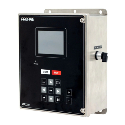
ProFire PF2200-SB User manual

PF2200-SB
USER GUIDE

TABLE OF CONTENTS
OVERVIEW....................................................................................................................................................... 3
STATUS LED ................................................................................................................................................................ 3
STARTING/STOPPING ................................................................................................................................................. 4
NAVIGATION............................................................................................................................................................... 4
MENU MAP................................................................................................................................................................. 5
STATUS SCREEN.......................................................................................................................................................... 6
OPERATIONAL STATES......................................................................................................................................7
POWER ON STATE....................................................................................................................................................... 7
LOCKOUT STATE ......................................................................................................................................................... 7
ALARM STATE ............................................................................................................................................................. 8
READY STATE .............................................................................................................................................................. 8
WAITING STATE.......................................................................................................................................................... 9
IGNITION STATE........................................................................................................................................................ 10
PILOT STATE.............................................................................................................................................................. 11
MAIN LIGHT-OFF STATE............................................................................................................................................ 11
PROCESS CONTROL STATE........................................................................................................................................ 12
SETTINGS....................................................................................................................................................... 13
TEMPERATURE INPUTS............................................................................................................................................. 13
FLAME DETECTION I/O (ION +/-) .............................................................................................................................. 14
EMERGENCY SHUTDOWN INPUT ............................................................................................................................. 15
LEVEL/FLOW INPUT.................................................................................................................................................. 15
PRESSURE INPUT ...................................................................................................................................................... 15
AUXILIARY INPUTS.................................................................................................................................................... 15
SYSTEM SCREEN............................................................................................................................................. 16
EVENT LOG SCREEN .................................................................................................................................................. 16
DATA LOGGING SCREEN ........................................................................................................................................... 16
SYSTEM DIAGNOSTICS SCREEN ................................................................................................................................ 17
FLAME DIAGNOSTICS SCREEN .................................................................................................................................. 18
STATUS PRIORITY SCREEN ........................................................................................................................................ 18
ABOUT SCREEN......................................................................................................................................................... 18
RESET/BACKUP/RESTORE SETTINGS ........................................................................................................................ 19
CERTIFICATIONS............................................................................................................................................. 19
TROUBLESHOOTING....................................................................................................................................... 19

OVERVIEW
This User Guide is intended to help the Operator use the PF2200-SB Burner
Management System.
The keypad located on the front of the unit is the primary method for the
operator to interface with the PF2200 system. It allows for screen
navigation, starting and stopping the burner, as well as allowing
commissioning and adjusting the PF2200 system.
STATUS LED
The Status LED indicator on the front of the PF2200 shows the status of the appliance. The chart below
shows the different states indicated by Status LED.
Below is a description of the different alerts found on the PF2200-SB.
•Alarms - A persistent abnormal condition in either the equipment, or the process.
•Waits - An event causing the BMS to de-energize all safety outputs. when the event clears, the
system is free to recycle.
•Warnings - An event that indicates a possible issue that may arise, but allows the system to
continue running.
•Main Permissive - an event that causes the BMS to de-energize the main solenoid outputs (SSV),
or an Alarm event shuts the system down.
For more information on the PF2200 systems states, see the "OPERATIONAL STATES" on page 10 section
below.

STARTING/STOPPING
Starting, and stopping the burner can be done by selecting the Start or Stop button on
the PF2200.
When starting the system, press the Start button. The system prompts for an
acknowledgment of this action. Press the OK or Start button again to continue with the
safe start-up of the burner. When shutting down the burner, press the Stop button. The
system prompts the user to confirm the shutdown, press OK or the Stop button again.
When the shutdown process is complete, the system will prompt for an acknowledgment that the
shutdown is complete. Press OK to acknowledge the shutdown.
Starting and stopping the burner can also be done with the optional manual
Start/Stop switch. There are three functional positions as shown. When in the stop
position, all safety outputs are de-energized. Toggling from the Run position to the
Ignite position for more than 2 seconds initiates the ignition sequence. Toggling
the switch from the Stop position to the Run and back to the Stop position can
clear a lockout state.
The optional Manual Switch part number PFA-004260 mentioned above can be ordered by contacting
Profire Energy.
Note: Holding the switch in the Ignite position for more than 4.5 seconds results in a system shutdown on
an External Stuck Switch event.
NAVIGATION
See the PF2200-SB Installation Manual for more information on the commissioning of the PF2200-SB.

MENU MAP
Note: The above diagram shows the menu map of the PF2200 in User Mode. This mode has a limited
menu item and options capability.

STATUS SCREEN
•The Status screen can show different
layouts based on a set of priorities that can
be customized in the System screen under
the Status Priority menu item.
•To switch through the different status
screen layouts, use the Plus and Minus
keys while in operation.
•The information displayed in the status screen is dependent on the activation of the various
settings. To change the Priority of what is shown, use the Carousel key to navigate to the System
screen. Use the Arrow keys to highlight Status Priority and press OK. You will then be presented
with a list of all active settings that can be shown in prominence on the status screen. Using the
Arrow keys and the Plus or Minus keys you can change what Status Elements have the higher
priority.

OPERATIONAL STATES
This section describes the different states of the PF2200-SB and outlines the behavior of the system in
each state.
POWER ON STATE
Power On is the default state of the system when power is applied.
If a previous lockout condition is present, the system transitions into the lockout state.
If the system previously shuts down due to a power loss, and the Low Voltage Re-start setting is enabled,
the system purges, and then proceeds to automatically restart the system.
If there are no lockouts, and the system is not automatically re-starting, then the system transitions into
the Ready state.
In this system state, the status of each powered output is as follows:
Powered Output
Status
Pilot 1 / 2
De-energized
Coil 1 / 2
De-energized
SSV
De-energized
HFV
De-energized
LOCKOUT STATE
will stay in the Lockout state until the Lockout is acknowledged by the user.
There are four ways to acknowledge a lockout:
•User Interface: Using the keypad to acknowledge the lockout state.
•Toggling of the Start input: From energized to de-energized.
•Toggling of the Start/Stop Switch: Turning the Optional Manual switch to the Stop position, then
back to the Run position.
•Modbus Interface: Writing the Acknowledge command to clear the shutdown code modbus
register.

In the Lockout state, the status of each powered outputs is as follows:
Powered Output
Status
Pilot 1 / 2
De-energized
Coil 1 / 2
De-energized
SSV
De-energized
HFV
De-energized
For more information on Modbus Register commands, refer to Modbus Registers.
ALARM STATE
indicative of a static problem (e.g., - transmitter not connected, system voltage too low, etc.). The system
can only exit this state when all alarms have cleared.
Once all Alarms are cleared, the system will transition to the Ready state.
In the Alarm state, the status of each powered output is as follows:
Powered Output
Status
Pilot 1 / 2
De-energized
Coil 1 / 2
De-energized
SSV
De-energized
HFV
De-energized
READY STATE
Ready is the system state where the system is idle, and no alarms are present. If there are any alarms
present while in this state, the system moves to the Alarm state. In the Ready state, the system may
proceed to start by one of the following methods:
•Pressing the Start button on the Keypad.
•When the remote start setting is enabled, toggling of the Start input from Open to Closed.
•Holding the Start/Stop switch in the ignite position for greater than 2 seconds.
•Modbus interface starts by writing a start command to the start stop register modbus register.

In this system state, the status of each powered output is as follows:
Powered Output
Status
Pilot 1
De-energized during Pre-Ignition
Pilot 2
De-energized if disabled
Same as Pilot 1 if enabled
Coil 1
De-energized during startup delay
Coil 2
De-energized if disabled
Same as Coil 1 if enabled
SSV
De-energized
HFV
De-energized
For more information on Modbus Register commands, refer to Modbus Registers.
WAITING STATE
Waiting is considered a “running” state of the system, with all powered outputs de-energized. The system
holds this state until all wait conditions have been cleared. Once all waits have been cleared the system
automatically begins the start-up sequence.
Note: purging after a flame loss is considered a wait.
Powered Output
Status
Pilot 1
De-energized during Pre-Ignition
Pilot 2
De-energized if disabled
Same as Coil 1 if enabled
Coil 1
De-energized during startup delay
Coil 2
De-energized if disabled
Same as Coil 1 if enabled
SSV
De-energized
HFV
De-energized

IGNITION STATE
Ignition is the state where a pilot flame is established, and the system achieves this by energizing the coil
and pilot outputs while monitoring flame presence on the ionization inputs.
If a flame is not detected within the pilot-flame establishing period of 4 seconds, the system purges and
restarts the ignition sequence. If the system fails to establish flame 3 consecutive times, the system
proceeds to a lockout state.
If the flame is detected within the Pilot-Flame Establishing period, the system holds the pilot flame for the
user configurable pilot start up delay time to help warm up the appliance, and establish a draft. once the
pilot start up delay time has elapsed, the system transitions to the Pilot State.
Actuating and monitoring of Pilot 2 can be enabled or disabled via the user interface and should only be
enabled if multiple pilots are in use.
If Pilot 2 is enabled, the system requires both flames to be satisfied within the Pilot-Flame Establishing
Period in order to proceed.
If Pilot 2 is disabled, the system only requires Pilot 1 flame to be satisfied within the Pilot-Flame
Establishing Period in order to proceed.
Any Alarms or Waits that occur during this state will cause the system to transition to a Lockout state, or a
Waiting state respectively.
In this system state, the status of each powered outputs is as follows:
Powered Output
Status
Pilot 1
Energized *
Pilot 2
De-energized if disabled
Same as Pilot 1 if enabled
Coil 1
Energized during Ignition
De-energized during startup delay
Coil 2
De-energized if disabled
Same as Coil 1 if enabled
SSV
De-energized
HFV
De-energized
*: The Pilot Outputs are energized 500ms after the Coil Outputs.

PILOT STATE
The Pilot state is the system state which represents a minimum amount of heating required to light off the
main burner. It is typically tied to the Pilot valve in the fuel gas train –meaning that the pilot valve(s) are
on in this state but, the main valves are off.
Once in Pilot state, the system must verify all configured process temperatures are below their respective
process setpoints and, main permissive(s) (if configured) have been cleared in order to enter the Main
Light Off state.
Any Alarms or Waits that occur during this state will cause the system to transition to a Lockout state, or a
Waiting state respectively.
The system exits Pilot state and transition to Pre-purge state in the event of Pilot Flame loss for more than
4 seconds. This is regardless of whether pilot two is enabled and does not suffer a flame loss.
In the Pilot state, the status of each powered outputs is as follows:
Powered Output
Status
Pilot 1
Energized
Pilot 2
De-energized if disabled
Energized if enabled
Coil 1 & 2
SSV
HFV
De-Energized
MAIN LIGHT-OFF STATE
The system enters the Main Light Off state from the Pilot state when the controller is calling for more
heat. If the system enters the Main Light Off state as part of a fresh startup, the Main Light Off state holds
for the user configurable main startup delay time. To help establish a draft and heat up the appliance
before the mains.
If the system enters the Main Light Off state from a Process Control state the Main Startup Delay Time is
fixed at 5 seconds since a draft has already been established and the appliance is already warm.
In addition, the Main Light Off state facilitates the option of proving Main Light Off position. When the
proof of light off input (POL) is enabled, the Main Light Off state holds until the position has been proven.
If position cannot be proven within 60 seconds the system transitions to lockout state.
Any Alarms or Waits that occur during Main Light Off state will cause the system to transition to Lockout
state or a Waiting state, respectively.
When the Main Light Off Position is enabled, and the system fails to establish Main Light Off in the Main
Light Off Timeout, the system exits to a Lockout state and triggers a Post purge.
In the Main Light Off state, the status of each powered outputs is as follows:

Powered Output
Status
Pilot 1
Energized
Pilot 2
De-energized if disabled
Energized if enabled
Coil 1 & 2
SSV
HFV
De-Energized
PROCESS CONTROL STATE
Once the system has determined the mains can be turned on, it enters the Process Control state. In this
state, the system actively tries to maintain the process temperature setpoint via the actuation of valves in
various configurations.
There are three main process control modes offered, and they are:
1. On/Off Control
2. Staged Heating
3. PID Control
Refer to the PF2200 Product Manual for more information on these three modes listed.
Any alarms or waits that occur during this state forces the system to transition to the Alarm state or a
Waiting state, respectively.
If Pilot Mode is set to Interrupted Pilot, the system transitions to Pre-purge if there is a Flame Loss for
more than 1 second. If relights remaining is zero, the system transitions to the Lockout state.
In the Process Control state, the status of each powered outputs is as follows:
Powered
Output
Status
Pilot 1
Energized
Pilot 2
De-energized if disabled
Energized if enabled
Coil 1 / 2
De-Energized
SSV
HFV
Energized or De-energized, depending on the process control state. See process
control modes below for specific valve behavior.
For more information on the different operational sates of the PF2200-SB see the Operational States
section found in the Product Manual here. For more information on setting up a PID see the PF2200
PID TUNING GUIDE.

SETTINGS
The Settings screen is accessed from any screen by using the Carousel key. Use the Arrow keys to
navigate between setting and the Plus or Minus keys to adjust setting.
A Password is required for some setting changes. For more information on Passwords, see the section on
Passwords found in the Installation Guide.
Once the Password is entered, you are returned to the settings screen where you can proceed to make the
necessary changes. This authentication mode is valid for 15 minutes regardless of activity.
In the case of a drop-down menu, press the OK key to open the drop-down, use the Arrow keys to
highlight your selection, press the OK key to make the setting change.
Commissioning mode is a view that allows access to the full settings menu. Please refer to the
COMMISSIONING section of the Installation Guide for more information on the Commissioner mode. To
exit Commissioning mode, and return to User mode, press the Commissioning button. The user is then
presented with an acknowledgment prompt.
TEMPERATURE INPUTS
The PF2200-SB has three distinct temperature inputs: Bath, Outlet, and Stack; each of which is
configurable to be either a Type-K thermocouple or PT-100 RTD input.
The following is a description of each of the setpoints and available setpoints for each Input:
•High-Temperature ESD Setpoint: the temperature at which the system shuts down. If the
temperature input exceeds this trip point, the system generates an alarm and if running proceed
to lockout
•Pilot Off Setpoint: the temperature at which the system de-energizes all valves, including the pilot,
and enters a waiting state. When the temperature falls back down below this value minus the
deadband, the system reignites the pilot.
•Main Off Setpoint: the temperature at which the system de-energizes the main valves and enters
the Pilot state. The main valves are turned back on when the temperature drops below the
Process Control Setpoint minus the deadband.

•Process Control Setpoint: The setpoint about which the process temperature is controlled. In PID
mode, the TCV is actuated in relation to this setpoint. In Staged Heating mode, the HFV is
actuated by this setpoint.
•Low-Temperature Warning Setpoint: If the temperature drops below this trip point, the system
displays a warning on the user interface and continues to run.
Setpoint
Description
High-Temperature
ESD Setpoint
The temperature at which the system shuts down. If the temperature input
exceeds this trip point, the system will generate an alarm and if running proceeds
to lockout.
Pilot Off Setpoint
The temperature at which the system de-energizes all valves, including the pilot,
and enters a waiting state. The system will reignite the pilot when the
temperature falls below the Process Setpoint minus the deadband.
Main Off Setpoint
The temperature at which the system de-energizes the main valves and enters the
Pilot state. The main valves will reignite when the temperature drops below the
Process Control Setpoint minus the deadband.
Process Control
Setpoint
The setpoint at which the process temperature will be controlled. In PID mode,
the TCV will be actuated in relation to this setpoint. In Staged Heating mode, the
HFV will be actuated by this setpoint.
Low-Temperature
Warning Setpoint
If the temperature drops below this trip point the system will display a warning on
the user interface and will continue to run.
FLAME DETECTION I/O (ION +/-)
Two Ionization flame detection I/O's are supported by the PF2200-SB. These terminals are intended to be
connected to a flame rod which makes physical contact with the flame.
Through the use of the rectification property of the flame, the PF2200-SB measures the presence of a
flame by applying an AC signal to the rod. If an open circuit event exists, the result is Loss of Flame.
Pilot 1 flame detection is always enabled, whereas Pilot 2 flame detection can be enabled or disabled via
the user interface. If Pilot 2 flame detection is enabled, both Pilot 1 and Pilot 2 flames must be established
and present for the system to continue to run.

For troubleshooting a Flame detection issue, see the Troubleshooting section at the end of this document.
EMERGENCY SHUTDOWN INPUT
The Emergency Shutdown Input (ESD) is an energized-to-run digital input that is always enabled. If the
contact is de-energized, the system presents an alarm and proceeds to lockout (if running). If the contact
is energized, the alarm clears.
Note: This digital input is self energized by the PWR terminal and does not need to be energized by the
user.
LEVEL/FLOW INPUT
The Level/Flow input is meant to monitor an external level (e.g., tank level), and provide the necessary
feedback in the event of a high or low-level event. The Level Input is configurable as either Disabled,
Digital Input, or 4-20mA signal through the user interface. The level input can be connected to either a
switch or transmitter.
PRESSURE INPUT
The Pressure Input is meant to monitor an external pressure (e.g., fuel pressure), and provide the
necessary feedback in the event of a high and/or low- pressure event. The Pressure Input is configurable
as either Disabled, Digital Input, or 4-20mA signal through the user interface; the pressure input can be
connected to either a switch or transmitter.
AUXILIARY INPUTS
The Auxiliary Inputs 1 and 2 are intended to be connected to a generic I/O device that may not fit into any
of the above-mentioned categories. Configurable as either a digital or 4-20mA input, this input is
intended to be connected to either a switch / PLC output (digital) or transmitter (4-20mA). The Auxiliary
Inputs have trip modes of Alarm, Wait, Warning, and Main Permissive.
For information on all the various Inputs and outputs of the PF2200-SB visit the Inputs and Outputs
sections of the Product Manual.

SYSTEM SCREEN
The System Screen gives access to system
tools and troubleshooting information,
including Event and Data Logging,
Diagnostics, Firmware updates, as well as the
Status Priority customization settings. Also
contained in the System Screen is the Reset,
Backup, and Restore options.
A supplied USB Storage device records system
events as well as data logs which are used for
information and troubleshooting.
EVENT LOG SCREEN
The PF2200-SB event log continuously records Alarms, Warnings, Shutdowns, and Process control
decisions as well as general system information and stores it on the USB storage device (if installed).
While in the Event Log screen, press the OK key to open the filters screen. Use the Arrow Up and Down
keys to underline the desired filter. Press the OK key to make the selection. When complete, use the
Down Arrow key to go to navigate to highlight the “Accept” button. Press the OK key to accept the
selections and return to the filtered event log.
When the supplied USB storage device is installed in the USB port on the back of the enclosure door, the
system will automatically log events to the storage device. The data saved is stored on a provided
USB storage device, and when the USB device becomes full the oldest data will be overwritten by the
newest data.
DATA LOGGING SCREEN
The PF2200-SB data logging tool will monitor various input and output data and will automatically log the
data to the supplied USB storage device.
Use the keypad to choose up to 8 items to log to the USB. The sample interval rate for data collection is
15 seconds. The Data logger creates folder for each individual data logging set, and creates a .CSV file

that can be opened and inspected. when the USB storage device becomes full the logging will begin to
delete the oldest logs to make room for the newest logs recorded.
The statistics dialog will show an approximation of logging time remaining on the USB before old logs
start getting deleted.
SYSTEM DIAGNOSTICS SCREEN
Diagnostics allows the user to get an organized view of all the diagnostic values on the system. Use the
Up and Down Arrows to scroll through the information presented.

FLAME DIAGNOSTICS SCREEN
Under the Flame Diagnostics screen, the Flame Strength and Diagnostic Voltage are displayed. This screen
also records the number of Flame Fails and Relights. On the right portion of the screen, you are shown a
graphical representation of the flame quality.
STATUS PRIORITY SCREEN
The Status Priority screen allows the user to adjust the status screens in accordance to the desired
information for the application of the system.
ABOUT SCREEN
The About screen displays important system information about the unit including, serial numbers as well
as firmware versions.

RESET/BACKUP/RESTORE SETTINGS
Reset, Backup, and Restore functions allow the user to save, reset, and restore settings quickly and easily.
Once you have the settings as desired, you can backup the settings to a USB stick, allowing you to copy
settings quickly to other units. The Reset function returns the settings to the factory defaults. To restore or
copy the settings to a unit, insert the USB stick with the settings backup on it. Use the Restore function to
update the settings from the backup.
Refer to the PF2200-SB Manual for more information on the Systems screen.
FIRMWARE UPDATE
The Firmware update function can be used to update the system with approved Profire Firmware Bundles.
Refer to the Firmware Update Guide for more information on the Firmware Update process.
Note: To confirm the update was successful, navigate to the About screen after the reboot to verify the
Burner Management System, and the User Interface versions are correct.
CERTIFICATIONS
The PF2200-SB (Single Burner BMS) is certified to the following standards:
•IEC 61508:2010, SIL 2
The PF2200-SB is pending certification to the following standards:
•UL 60730-2-5/ANSI Z21.20-2014 & UL 121201
•CSA C22.2 No. 60730-2-5 & C22.2 No. 213
•CSA C22.2 No. 213-17
TROUBLESHOOTING
For a complete list of Alerts and there meaning, refer to the PF2200 ALERT CODES.
Problem
Diagnosis
The System has visible flame but
cannot detect
1. Ensure pilot assembly, flame rod, and the gap between are
fully engulfed in flame. If not, adjust rod position.
2. Ensure flame detection wiring does not exceed the
recommended maximum length.
3. Ensure burner assembly has a low impedance path to Ion-
terminal of BMS.
4. For longer run lengths, ensure ignition cable is used to
avoid ground-loading.
The System is unresponsive or BMS
card will not communicate with User
Interface card
1. Ensure the Status LEDs for both cards are functioning. If
status LED is not functioning, cycle power (if safe to do so)
and check again.
2. If status LED is still not functioning, attempt a firmware
update of both cards.

Problem
Diagnosis
3. If firmware update fails, card is likely faulty.
The Ignition transformer “clicks” but no
visible spark
1. Ensure all wires in the ignition path are properly
terminated and that there is a low impedance path from the
primary-windings to the BMS card as well as the secondary-
windings to the ignition rod.
2. Ensure the gap between the ignition rod and the burner
housing is within the tolerances specified in this manual
under PF2200 Declarations section under ”High Voltage
Spark Gap Range”. Often times there is either excess buildup
or the rod has drooped to compromise the gap distance.
Solenoids are not turning on, or
turning on then over time turn off
1. Ensure the solenoid is wired correctly and to the
appropriate terminals.
–To ensure proper solenoid wiring, a multi-meter in OHM
mode can be used to measure the resistance between the +
and –terminal of the associated output. Note: this
measurement should be done with the BMS card powered
off.
–If properly wired, the multi-meter should read a resistance
of the solenoid coil plus the run length (i.e. if the multimeter
reads open, there is likely a problem with wiring).
2. Ensure the PWM setting is correct for the appropriate
solenoid.
–If using a peak-and-hold solenoid, the appropriate PWM
setting can be found in the solenoid data sheet. Typically add
a margin of 5-10% to allow for temperature variance
–If using a non-peak-and-hold solenoid, ensure the PWM
setting is set to 100%
Digital input will not energize
1. Ensure the input is properly wired. See section 4 for
Interfacing / Wiring configurations.
2. In the case of a dry contact, ensure the PWR terminal is
connected and is sourcing the correct voltage.
3. Ensure adequate amount of wetting current is being
applied through contact.
–Run a current meter in series with the digital input switch
and verify the energized state meets the requirements
outlined in the “Electrical and Mechanical Ratings” section of
this document
–If there is not adequate wetting current, the digital input
either has too high of an impedance or the wiring has been
compromised
Other manuals for PF2200-SB
4
Table of contents
Other ProFire Controllers manuals
Popular Controllers manuals by other brands

AKE
AKE AKE.370.502.01.03 user manual

Concoa
Concoa 522 Series Installation and operation instructions
Emerson
Emerson Dixell XT130C Installing and operating instructions
industrie technik
industrie technik SE5M24 Instruction
Elation
Elation ELAR-DRIVER-8-12V user manual
Honeywell
Honeywell SILENT KNIGHT SK-Control nstallation and Maintenance Instructions
