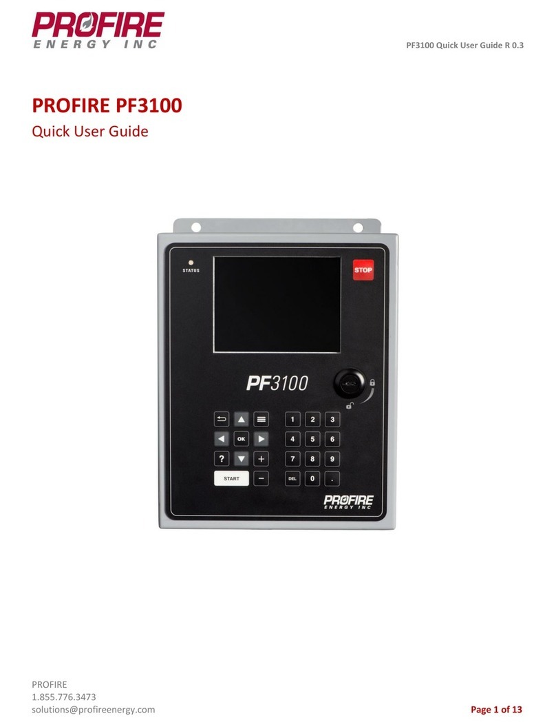
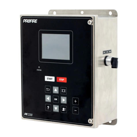
ProFire PF2200-SB User manual

V 4.0
Page 1of 85
PF2200-SB
PRODUCT MANUAL

V 4.0
Page 2of 85
PROPRIETARY INFORMATION: THIS DOCUMENT IS PREPARED BY PROFIRE ENERGY FOR THE USE OF OUR CUSTOMER. PROFIRE ENERGY ASSUMES NO LIABILITY TO
ANY OTHER PARTY FOR ANY REPRESENTATIONS CONTAINED HEREIN.
Table of Contents
1INTRODUCTION................................................................................................................................................... 4
1.1 SCOPE AND PURPOSE .................................................................................................................................................4
1.2 TERMS AND ABBREVIATIONS .....................................................................................................................................5
1.3 ACRONYMS .................................................................................................................................................................7
1.4 PRODUCT SUPPORT ..................................................................................................................................................8
1.5 RELATED LITERATURE................................................................................................................................................8
1.6 REFERENCE STANDARDS...........................................................................................................................................8
2PF2200-SB PRODUCT DESCRIPTION ...................................................................................................................9
2.1 PRODUCT OVERVIEW.................................................................................................................................................9
2.1.1 USER INTERFACE CARD.................................................................................................................................................10
2.1.2 BMS CARD .....................................................................................................................................................................11
2.1.3 KEYPAD ..........................................................................................................................................................................24
2.1.4 ENCLOSURE...................................................................................................................................................................26
2.2 OPERATING SEQUENCE ..........................................................................................................................................28
2.2.1 POWER ON ....................................................................................................................................................................29
2.2.2 LOCKOUT.......................................................................................................................................................................29
2.2.3 READY ............................................................................................................................................................................30
2.2.4 ALARM............................................................................................................................................................................30
2.2.5 WAITING ........................................................................................................................................................................31
2.2.6 IGNITION .......................................................................................................................................................................31
2.2.7 PILOT..............................................................................................................................................................................32
2.2.8 MAIN LIGHT OFF ...........................................................................................................................................................33
2.2.9 PROCESS CONTROL ......................................................................................................................................................34
2.3 GENERAL REQUIREMENTS ......................................................................................................................................37
2.3.1 PF2200 DECLARATIONS ...............................................................................................................................................37
2.4 CERTIFICATION AND APPROVALS............................................................................................................................38
3INSTALLATION AND COMMISSIONING ...........................................................................................................39
3.1 SYSTEM CONFIGURATION ......................................................................................................................................39
3.1.1 PASSWORDS ..................................................................................................................................................................39
3.1.2 Interfacing.....................................................................................................................................................................40
3.1.3 ELECTRICAL and MECHANICAL RATINGS....................................................................................................................43
3.2 IMPORTANT SAFETY INFORMATION......................................................................................................................46
3.2.1 GENERAL WARNINGS....................................................................................................................................................46
3.2.2 EXPLOSION HAZARD WARNINGS ................................................................................................................................47
3.2.3 INSTALLATION WARNINGS...........................................................................................................................................47
3.3 MOUNTING CONSIDERATIONS..............................................................................................................................47
3.3.1 ORIENTATION & LOCATION .........................................................................................................................................48

V 4.0
Page 3of 85
3.3.2 MOUNTING CARDS .......................................................................................................................................................49
3.3.3 PROTECTIVE EARTHING ................................................................................................................................................50
3.3.4 ELECTRICAL NOISE........................................................................................................................................................50
4OPERATIONS AND MAINTENANCE ..................................................................................................................51
4.1 ASSUMPTIONS SPECIFIC TO USE.............................................................................................................................51
4.2TRANSPORTATION &STORAGE CONDITIONS......................................................................................................51
4.3 OPERATOR USER INTERFACE..................................................................................................................................51
4.3.1 SYSTEM NAVIGATION ...................................................................................................................................................51
4.3.2 SETTINGS .......................................................................................................................................................................53
4.3.3 SETTINGS MAPS ............................................................................................................................................................57
4.3.4 SYSTEM SCREEN............................................................................................................................................................67
4.4 TROUBLESHOOTING ...............................................................................................................................................74
4.5 MAINTENANCE.........................................................................................................................................................75
4.6 REPAIR AND REPLACEMENT.....................................................................................................................................76
4.7 DECOMMISSIONING................................................................................................................................................76
4.8 USEFUL LIFE ..............................................................................................................................................................77
4.9 MANUFACTURER NOTIFICATION ...........................................................................................................................77
5DOCUMENT REVISION HISTORY.......................................................................................................................79
6APPENDIX A: ALARM CODES & RESPONSE TIMES ...........................................................................................80

V 4.0
Section 1: INTRODUCTION
Page 4of 85
1INTRODUCTION
1.1 SCOPE and PURPOSE
This document is intended to be a full description of the PF2200-SB product and the intended use in
accordance with the product life cycle. This document outlines the following:
•PF2200-SB Product Description: this section describes the intended use of the product; including
I/O, operating sequence, general requirements and approvals
•Installation and Commissioning: this section describes the actions needed to perform
installation and commissioning of the PF2200-SB; including electrical/mechanical ratings,
configuration parameters, mounting considerations and warnings
•Operations and Maintenance: this section describes the actions needed for ongoing operation
and maintenance of the PF2200-SB; including troubleshooting, maintenance, repair and
replacement, decommissioning and manufacturer notification

V 4.0
Section 1: INTRODUCTION
Page 5of 85
1.2 TERMS and ABBREVIATIONS
Alarm
An indication of an abnormal condition in either the equipment or the process.
Continuous Pilot
A pilot which, once placed in operation, is intended to remain ignited continuously until
it is manually interrupted
Digital Input
An input to the system that can be one of only two states (Energized or De-energized).
Electronic
Disconnection
Non-cycling interruption by an electronic device of a circuit for functional disconnection
which provides a disconnection other than by means of an air gap by satisfying certain
electrical requirements in at least one pole
Flame Detector
Device which provides the programming unit with a signal indicating the presence of
absence of flame
Flame Detector
Response Time
Period of time between loss of the sensed flame and the signal indicating the absence
of flame
Flame Detector Self-
Checking Rate
Frequency of self-checking function of the flame detector (in number of operations per
unit of time)
Flame Failure Lock-
out Time
Period of time between the signal indicating absence of flame and lock-out
Full Rate Start
Condition in which the main burner ignition and subsequent flame supervision occur at
full fuel rate
Ignition Time
Period of time during which the ignition device is energized
Incorporated
Control
Control intended for incorporation in, or on, an equipment, but which can be tested
separately.
Intermittent Pilot A pilot which is automatically ignited when an appliance is called on to operate and
which remains continuously ignited during each period of main burner operation. The
pilot is automatically extinguished when each main burner operating cycle is
completed
Interrupted Ignition
A type of ignition which is energized prior to the admission of fuel to the main burner
and which is de-energized when the main flame is established
Interrupted Pilot
A pilot which is automatically ignited prior to the admission of fuel to the main burner
and which is automatically extinguished when the main flame is established
Lockout
A state in which all powered outputs (Valves and Ignition) are de-energized and
interaction from the user is required in order to exit the state.
Low Rate Start
Condition in which main burner ignition occurs at low fuel rate. Once ignition at low
fuel rate occurs and the flame is proven, full main burner fuel rate may be admitted
Main Permissive
An event which causes the BMS to de-energize the main solenoid outputs (SSV) and
remain in that state until the event clears (or an alarm / wait condition forces the BMS
out)

V 4.0
Section 1: INTRODUCTION
Page 6of 85
Maximum Flame-
failure Re-ignition
Time
Period of time between the signal indicating absence of flame and the signal to
energize the ignition device. During this time period the fuel supply is not shut off.
Non-volatile
Lockout
Condition such that a restart can only be accomplished by a manual reset of the
system and by no other cause
Permanent
Operation
System which is intended to remain in the running position for longer than 24 h
without interruption
Pilot-flame
Establishing Period
Period of time between the signal to energize the pilot fuel flow means and the signal
indicating presence of the pilot flame
Post-Ignition Time
Period of time between the signal indicating presence of flame and the signal to de-
energize the ignition device
Post-Purge Time
Purge time that takes place immediately following the shutting off of the fuel supply
Pre-Ignition Time
Period of the ignition time between the signal to ignite and the signal to energize the
fuel flow means
Pre-Purge Time Purge time that takes place between initiation of a burner control sequence and the
admission of fuel to the burner
Recycle Time
Period of time between the signal to de-energize the fuel flow means following the loss
of flame and the signal to begin a new start-up procedure
Safety Output
A powered electrical output from the PF2200 BMS card designed to control safety
actuators (e.g. safety shut off valves, ignition coils, etc.). Safety Outputs of the PF2200
BMS card are as follows: Pilot 1, Pilot 2, SSV, High Fire, Coil 1, and Coil 2.
Safety-interlock
A term used to describe an input (either switch or Transmitter) that must be satisfied to
run. If the interlock is not satisfied (e.g. open switch or out of range transmitter) the
system will proceed to lock-out.
Shutdown
The process the system goes through when it receives an alarm event while running.
This is immediately followed by entering the state of Lockout.
Signal for Absence
of Flame
Maximum signal which indicates the loss of flame
Signal for Presence
of Flame
Minimum signal which indicates the presence of flame when there was previously no
flame
Start-up Lock-out
Time
Period of time between the signal to energize the fuel flow means and lock-out
Type 2 Action
Automatic action for which the manufacturing deviation and the drift of its operating
value, operating time, or operating sequence have been declared and tested under the
IEC 60730 standard.
Wait
An event which causes the BMS to proceed to a state which will de-energize all safety
outputs. When all wait events clear, the BMS is free to automatically recycle.
Waiting Time
Period between the start signal and the signal to energize the ignition device. For
burners without fans, natural ventilation of the combustion chamber and the flue
passages normally takes place during this time.

V 4.0
Section 1: INTRODUCTION
Page 7of 85
1.3 ACRONYMS
BMS Burner Management System
ESD Emergency Shut Down – a mechanism that shuts down the system in the
event of a safety emergency
FIT Failure In Time (unit) – represents the number of failures occurring in 109
hours
FMEDA Failure Mode, Effects and Diagnostic Analysis
HFT Hardware Fault Tolerance
HFV High Fire Valve
I/O Generic name for a terminal that can be an input, output, or a combination
or both.
PFDAVG Average Probability of Failure on Demand
PF2200-SB Model number for the PF2200 Single Burner BMS product. Consists of:
BMS Card, User Interface Card, keypad, enclosure and ignition switch
PFN Profire Network. Method of communication between User Interface Card
and BMS Card.
PTC Proof Test Coverage
PWM Pulse Width Modulation
RTD Resistive Thermal Device
SIL Safety Integrity Level. A discrete level (one out of a possible four) for
specifying the safety integrity requirements of the safety functions to be
allocated to the E/E/PE safety-related systems where Safety Integrity Level 4
has the highest level of safety integrity and Safety Integrity Level 1 has the
lowest
SIF Safety Instrumented Function. A set of equipment intended to reduce
the risk due to a specific hazard (a safety loop)
SFF Safe Failure Fraction. The fraction of the overall failure rate of a device that
results in either a safe fault or a diagnosed unsafe fault
SSV Safety shutoff valve. A valve that shuts off for safety reasons.
TCV Temperature Control Valve

V 4.0
Section 1: INTRODUCTION
Page 8of 85
1.4 PRODUCT SUPPORT
Product support can be obtained from:
Profire Energy
1.855.776.3473
321 South, 1250 West Suite 1
Lindon, UT 84042, USA
support@profireenergy.com
1.5 RELATED LITERATURE
PF2200 Single Burner BMS – Modbus Registers
PF2200 Single Burner BMS – Software Release Notes
1.6 REFERENCE STANDARDS
IEC 61508:2000 Functional Safety of Electrical / Electronic / Programmable Electronic Safety-Related
Systems
CSA 22.2 No. 60730-2-5 / ANSI Z21.20:14
UL 60730-2-5
CSA 22.2 No. 213-17
UL 121201. ED9

V 4.0
Section 2: PF2200-SB PRODUCT DESCRIPTION
Page 9of 85
2PF2200-SB PRODUCT DESCRIPTION
2.1 PRODUCT OVERVIEW
The PF2200 Single Burner Controller (PF2200-SB) product is designed to provide safe and reliable
control over industrial heating appliances. This product consists of five main pieces:
•User Interface Card: the card which provides interaction to the user / operator. This card
monitors user input and displays all relevant status / setting information to the user.
•BMS Card: the “safety brain” of the product. This card stores all the relevant safety information
and performs the operating sequence in accordance with the timings in the safety settings.
•Keypad: allows the user / operator to interact with the product through a series of buttons.
•Enclosure: provides protection for the product against environmental conditions.
•Ignition Switch: allows the user / operator to Start and Stop the system via an external switch
located on the side of the enclosure

V 4.0
Section 2: PF2200-SB PRODUCT DESCRIPTION
Page 10 of 85
2.1.1 USER INTERFACE CARD
The User Interface Card allows interaction with the system through the use of the keypad and a display.
This card interacts with the BMS card through a proprietary communication protocol, called PFN, which
utilizes the RS-485 physical transport layer. PFN and power to the User Interface are factory wired to
the BMS card through a wiring harness.
2.1.1.1 MODBUS
Remote access to status information and non-safety critical settings can be achieved via the Modbus
port of the User Interface card. The Modbus port supports Modbus RTU over the RS-485 physical layer.
For a complete register list, see PF2200 Single Burner BMS – Modbus Registers. By design, safety critical
settings are not accessible via Modbus.
2.1.1.2 USB
The USB port of the User Interface Card has two main uses: data-logging and updating firmware.Data-
logging is enabled by going to the Firmware Update screen on the User Interface and is limited by the
size of USB stick-- a USB stick of size 1GB or larger is recommended. Firmware update is only
supported using authorized firmware bundles. Contact Profire Energy for an authorized firmware
bundle.
2.1.1.3 STATUS LED
The User Interface Card has a Status LED which is visible on the front panel of the product. Capable of
producing Red, Green and Amber colors, the states of the Status LED are defined below:
State
LED Behavior
System is not running and is in lockout
Fast Blink Red
System is not running and has an alarm
Blink Red
System is not running
Solid Red
System is running – no warnings or waits present
Solid Green
System is running – in wait state
Blink Green
System is running – in wait state with a warning present
Blink Amber
System is running – with a warning present
Solid Amber

V 4.0
Section 2: PF2200-SB PRODUCT DESCRIPTION
Page 11 of 85
2.1.2 BMS CARD
The BMS card provides the necessary I/O and functionality to reliably and safely control a burner. In
addition, the BMS card also has tertiary features that are not safety rated but provide a functional
benefit to the overall product.

V 4.0
Section 2: PF2200-SB PRODUCT DESCRIPTION
Page 12 of 85
2.1.2.1 PILOT VALVE OUTPUTS (Pilot 1 and Pilot 2)
Two powered outputs (terminals 15-16 and 17-18) are intended to be connected to solenoid valves
which control the fuel line for the pilot. When Pilot 2 is enabled, both outputs work in conjunction with
one another meaning that they energize and de-energize in unison.If Pilot 2 is disabled, the Pilot 2
output will stay de-energized.The Pilot Outputs are capable of PWM output mode at a fixed 3 kHz
frequency. Supported duty cycles for PWM mode are 10-100% and are configurable via the user
interface.
2.1.2.2 MAIN VALVE OUTPUTS (SSV)
Two powered outputs (terminals 19-20 and 21-22) are intended to be connected to solenoid valves
which control the main fuel line for the burner. Both outputs work in conjunction with one another
meaning that they energize and de-energize in unison. The Main Valve Outputs are capable of PWM
output mode at a fixed 3 kHz frequency. Supported duty cycles for PWM mode are 10-100% and are
configurable via the user interface.
2.1.2.3 IGNITION OUTPUTS (Coil +/-)
Two powered outputs (terminals 55-56 and 59-60) are intended to be connected to an ignition source
(e.g. ignition transformer). When Pilot 2 is enabled, both outputs work in conjunction with one another
meaning they energize and de-energize in unison. If Pilot 2 is disabled, the Pilot 2 Coil output will stay
de-energized. Two ignition modes are supported by the system and configurable via the user interface:
Coil Mode and High Energy Ignition (HEI) mode. Coil mode sends a pulsed signal of fixed frequency and
duty cycle and is intended to be used in conjunction with an ignition transformer. In HEI mode, the
output is energized with a steady state DC voltage that can be used to enable an external High Energy
Ignition source.
2.1.2.4 FLAME DETECTION I/O (Ion +/-)
Two Ionization flame detection I/O (terminals 53-54 and 57-58) are supported by the PF2200-SB. These
terminals are intended to be connected to a flame rod which makes physical contact with the flame.
Through the use of the rectification property of the flame, the PF2200-SB measures the presence of
flame by applying an AC signal to the rod. If an open circuit event exists, the result will be a loss of
flame.
Pilot 1 flame detection is always enabled, whereas Pilot 2 flame detection can be enabled or disabled
via the user interface. If Pilot 2 flame detection is enabled, both Pilot 1 and Pilot 2 flames must be
established and present in order for the system to continue to run.

V 4.0
Section 2: PF2200-SB PRODUCT DESCRIPTION
Page 13 of 85
2.1.2.5 HIGH FIRE VALVE (HFV) OUTPUT
One powered output (terminals 23 and 24) is intended to be connected to a solenoid valve when a
staged heating appliance is needed. In this application, the high fire valve output is intended to be the
highest level of heat demand (Stage 2). If a lower level of heat demand is needed, the high fire valve will
be de-energized while the Main Valve Outputs (SSV) will be energized (Stage 1).
2.1.2.6 START/STOP SWITCH
The external Start/Stop switch can be used to start, stop or clear a lockout on the system. The various
positions / actions are outlined in the table below:
Switch State
Behavior
Switch State Mode
Stop
Hold the system in lockout
ESD or Shutdown
Run
Transition to a ready state or maintain a running
state.
Ready
Ignite
If held for 1 second or more, transition into the
Confirm Start state.
System Start
Run -> Stop -> Run
Acknowledge and clear lockout condition
N/A
Note: if switch is held in the Ignite state for longer than 5 seconds, the system will alarm.
2.1.2.7 EMERGENCY SHUTDOWN (ESD) INPUT
The ESD input (terminals 33-34) is an energized-to-run digital input that is always enabled. If the
contact is de-energized, the system will present an alarm and proceed to lockout (if running). If the
contact is energized, the alarm will clear.

V 4.0
Section 2: PF2200-SB PRODUCT DESCRIPTION
Page 14 of 85
2.1.2.8 PRESSURE INPUT
The Pressure input (terminals 5-6) is meant to monitor an external pressure (e.g. fuel pressure) and
provide the necessary feedback in the event of a high and/or low pressure event. Configurable as
disabled, digital input or 4-20mA signal through the user interface; the pressure input can be connected
to either a switch or transmitter.
In digital input mode, the input can be configured as either an alarm, wait, warning or main permissive
when the contact opens. This is intended to be connected to a low pressure switch.
In 4-20mA mode, a high pressure trip event will cause an alarm and a low pressure trip event can be
configured as an alarm, wait, warning or main permissive. The aforementioned high-pressure trip
event will only alarm the system if the high pressure event persists after the mains have opened. This
mode is intended for use with a pressure transmitter.
The following table outlines the behavior of the Pressure Input:
Input Configuration
Event
System Behavior
Disabled
Any
No Effect
Digital Input
De-energized with low pressure mode set to Wait
Wait
De-energized with low pressure mode set to Alarm
Alarm
De-energized with low pressure mode set to Main
Permissive
Main Permissive
De-energized with low pressure mode set to Warning
Warning
Energized
Run
4-20mA
Out of range
Alarm
Low trip with low pressure mode set to Alarm
Alarm
Low trip with low pressure mode set to Wait
Wait
Low trip with low pressure mode set to Main
Permissive
Main Permissive
Low trip with low pressure mode set to Warning
Warning
Active range
Run
High trip with mains ON
Alarm
High trip with mains OFF
Run

V 4.0
Section 2: PF2200-SB PRODUCT DESCRIPTION
Page 15 of 85
2.1.2.9 LEVEL INPUT
The Level input (terminals 41-42) is meant to monitor an external level or flow measurement and
provide the necessary feedback in the event of a high and/or low level/flow event. Configurable as
disabled, digital input or 4-20mA signal through the user interface; the level input can be connected to
either a switch or transmitter.
In digital mode the level input can be used a wait, warning or an alarm when the contact opens. This
can be connected to a low or high trip switch depending on the application.
In 4-20mA mode the level input is used in conjunction with the low-trip and high-trip modes. These
modes are independent of one another and can be configured as either a wait, warning, or an alarm.
This input is intended to be connected to a level transmitter.
The following table outlines the behavior of the Level Input:
Input Configuration
Event
System Behavior
Disabled
Any
No Effect
Digital Input
De-energized with digital mode set to wait
Wait
De-energized with digital mode set to warning
Warning
De-energized with digital mode set to alarm
Alarm
Energized
Run
4-20mA
Out of range
Alarm
Low trip with low trip mode set to wait
Wait
Low trip with low trip mode set to warning
Warning
Low trip with low trip mode set to alarm
Alarm
Active range
Run
High trip with high trip mode set to wait
Wait
High trip with high trip mode set to warning
Warning
High trip with high trip mode set to alarm
Alarm

V 4.0
Section 2: PF2200-SB PRODUCT DESCRIPTION
Page 16 of 85
2.1.2.10 TEMPERATURE INPUTS
The PF2200-SB has three distinct temperature inputs: Bath, Outlet and Stack; each of which are
configurable to be either a Type-K thermocouple or PT-100 RTD input.
Each of the three distinct temperature inputs mentioned above have the following set points that can
be configured via the user interface (note: depending on the mode, the temperature input may or may
not utilize all the set points below; see Temperature Mode for more details):
•High Temperature ESD Setpoint: Temperature at which the system shuts down. If the
temperature input exceeds this trip point, the system will generate an alarm and if running
proceed to lockout
•Pilot Off Setpoint: Temperature at which the system de-energizes all valves, including the pilot,
and enters a waiting state. When the temperature falls back down below this value minus the
deadband, the system will reignite the pilot.
•Main Off Setpoint: Temperature at which the system de-energizes the main valves and enters
the Pilot state. The main valves will be turned back on when the temperature drops below the
Process Control Setpoint minus the deadband.
•Process Control Setpoint: The setpoint about which the process temperature will be controlled.
In PID mode, the TCV will be actuated in relation to this setpoint. In Staged Heating mode, the
HFV will be actuated about this setpoint.
•Low Temperature Warning Setpoint: If the temperature drops below this trip point the system
will display a warning on the user interface and will continue to run.

V 4.0
Section 2: PF2200-SB PRODUCT DESCRIPTION
Page 17 of 85
The three temperature inputs listed above also have a user-configurable mode. The various
temperature modes are defined below:
•Disabled: Temperature input is ignored.
•High Temp ESD: Temperature input is monitored for High Temp ESD event only. Setpoints used
in this mode: High Temperature ESD and Low Temperature Warning
•Process Control Mode: Temperature input is monitored for High Temp ESD event as well as
used for process control. Setpoints used in this mode: High Temperature ESD, Pilot Off, Main
Off, Process Control and Low Temperature Warning Setpoint.
•Display Only: Temperature inputs are read in and displayed on the User Interface. The system
does NOT act on this information in any way. Setpoints used in this mode: none.
Input
Terminals
Type
Modes Supported
Bath 61-66
Dual Element with cross comparison
Single Element
High Temp ESD
Process Control
Outlet 67-69 Single Element
Disabled
High Temp ESD
Process Control
Display Only
Stack 70-72 Single Element
Disabled
High Temp ESD
Display Only
2.1.2.11 PROOF OF CLOSURE (PoC) INPUT
The Proof of Closure input (terminals 11-12) is a digital input meant to be connected to a Proof of
Closure switch, indicating the closure of the main valve(s). An energized Proof of Closure input
indicates that the main valve is closed. The PF2200-SB monitors the Proof of Closure input and takes
action, as outlined in the table below.
Input Configuration
Event
System Behavior
Disabled
Any
No Effect
Digital Input
De-energized with main off
Alarm
De-energized with main on
Run
Energized
Run

V 4.0
Section 2: PF2200-SB PRODUCT DESCRIPTION
Page 18 of 85
2.1.2.12 REMOTE START INPUT
The Remote Start input (terminals 35-36) is a digital input intended to provide the ability to start the
system from an external source (e.g. a switch or PLC). The remote start input is an energized-to-run
input, meaning that if the contact is de-energized the system will proceed to a WAIT state. A toggle of
the start input from the de-energized to energized position causes the system to either clear a lockout
(if one is present) or start the system (if there are no alarms). This means that if a lockout is present
and the operator wishes to start the system, two toggles of the start contact is necessary (one to clear
the lockout, and the other to start the system). This functionality is outlined in the table below.
Input Configuration
Event
System Behavior
Disabled
Any
No Effect
Digital Input
De-energized and system is in a running state
Wait
De-energized and system is not running
No Effect
Transition from de-energize to energize
Acknowledge lockout if
present, start if no alarm
present
Energized
Run
2.1.2.13 HIGH PRESSURE INPUT
The High Pressure input (terminals 7-8) is a digital input intended to be connected to a high pressure
switch. This contact is energized to run, meaning that a non-energized contact indicates a high
pressure event. The high pressure functionality is outlined in the table below.
Input Configuration
Event
System Behavior
Disabled
Any
No Effect
Enabled
De-energized
Alarm
Energized
Run

V 4.0
Section 2: PF2200-SB PRODUCT DESCRIPTION
Page 19 of 85
2.1.2.14 PROOF OF MAIN LIGHT OFF (POL) INPUT
The Proof of Main Light Off input (terminals 9-10) is intended to be used in conjunction with either a
TCV capable of position feedback or a high-fire valve with light-off position indication. Capable of both
4-20mA and Digital modes, the Proof of Main Light Off input gives the system the ability to prove a light-
off position before opening the main gas valves.
In Digital mode this input connects to a proof of closure switch on the HFV OR with a proof of position
switch on a TCV. In 4-20mA mode this input connects to a TCV that has positional feedback. When in 4-
20mA mode, the system will monitor the position input and cross-check with the user-defined setpoint
& tolerance fields. In either mode the input is monitored only during the transition from pilot to main
in the request light off sequence. If the contact is not proven within 60 seconds the system will lockout.
Mechanically, the light off position proving requires a proof of closure valve for the HFV if the system is
utilizing staged heating control or in PID control mode a position switch / 4-20mA position feedback
signal from the TCV.
The following table outlines the functionality of the input.
Input Configuration
Event
System Behavior
Disabled
Any
No Effect
Digital Input
De-energized during pilot to main transition (60s
elapsed)
Alarm
Energized during pilot to main transition
System transitions to
main
De-energized or Energized in all other states
No Effect
4-20mA Input
Out of range
Alarm
Low trip or High Trip during pilot to main transition
(60s elapsed)
Alarm
Low trip, Active Range, or High Trip during all other
states
No Effect
Active range during pilot to main transition
System transitions to
main
2.1.2.15 AUXILIARY TEMPERATURE INPUT
The Auxiliary Temperature Input (terminals 43-44) is intended to be connected to a temperature sensor
with a 4-20mA interface. This 4-20mA input can be mapped to a temperature using the span settings
(Max and Min) and can be configured as: Disabled, High Temp ESD, Process Control, or Display Only.
For details on the individual modes and setpoints, see the Temperature Inputs section of this document.

V 4.0
Section 2: PF2200-SB PRODUCT DESCRIPTION
Page 20 of 85
2.1.2.16 AUXILIARY INPUTS
The Auxiliary Inputs 1 and 2 (terminals 45-46 and terminals 47-48 respectively) are intended to be
connected to a generic I/O device that does not fit into any of the above categories of inputs.
Configurable as either a digital or 4-20mA input, this input is intended to be connected to either a
switch/PLC output (digital) or transmitter (4-20mA).
The following table outlines the modes/behavior of the Auxiliary Input:
Input Configuration
Event
System Behavior
Disabled
Any
No Effect
Digital Input
De-energized (input mode set to Alarm)
Alarm
De-energized (input mode set to Wait)
Wait
De-energized (input mode set to Warning)
Warning
De-energized (input mode set to Main Permissive)
Main Permissive
Energized
Run
4-20mA
Out of range
Alarm
Low/High Trip (input mode set to Alarm)
Alarm
Low/High Trip (input mode set to Wait)
Wait
Low/High Trip (input mode set to Warning)
Warning
Low/High Trip (input mode set to Main Permissive)
Main Permissive
Active range
Run
Appliance Firing Rate
In addition to the features mentioned above, Auxiliary Input 1 has the ability to map to the appliance
firing rate. This input maps directly to the TCV output position (e.g. 4mA = 0%, 20mA = 100%). This is,
however, gated by the TCV minimum opening position. The TCV output position can only be set by
appliance firing rate during the process control state, in any other state it abides by the rules outlined in
the TCV section of this document.
When this mode is enabled, the process setpoint is ignored by the system and instead the TCV is
actuated based on the 4-20mA input.
If this input goes invalid or out of range the appliance firing rate will be set to 0% and an alarm will be
set to shut the system down.
Other manuals for PF2200-SB
4
Table of contents
Other ProFire Controllers manuals
Popular Controllers manuals by other brands
Bluesky
Bluesky SB3000i Installation and operation
Intech Instruments Ltd
Intech Instruments Ltd ezeio-STD Supplementary manual
Sunsystem
Sunsystem One DE Installation & operating instructions
TracoPower
TracoPower TSP-BCM24 operating instructions

FLORABEST
FLORABEST F Series Instructions for use

FRONIUS
FRONIUS SpotWelding operating instructions
