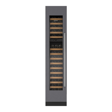
Sub-Zero WS Series User manual

1-2
#7013423 - Revision A - April, 2009
General Information W
Wine S
ine Storage (WS) Series
torage (WS) Series
TECHNICAL ASSISTANCE
If you should have any questions regarding the WS
Series and/or this manual, please contact:
Sub-Zero, Inc.
ATTN: Service Department
P.O. Box 44988
Madison, WI 53744 - 4988
Customer Assistance
Phone #: (800) 222 - 7820
Facsimile #: (608) 441 - 5887
Technical Assistance
(For Technicians in Customer’s Homes Only)
Phone #: (800) 919 - 8324
Warranty Claims
Phone #: (800) 222 - 7820
Facsimile #: (608) 441 - 5886
Service Department e-mail Address:
Office Hours:
7:00 AM to 7:00 PM Central Time
Monday through Friday
IMPORTANT SAFETY INFORMATION
Below are Product Safety Labels used in this manual.
The "Signal Words" used are WARNING or CAUTION.
When reviewing this manual, please note these differ-
ent Product Safety Labels placed at the beginning of
certain sections of this manual. You must follow the
instructions given in the boxes of the Product Safety
Labels in order to avoid personal injury and/or product
damage.
The sample Product Safety Labels below illustrate the
precautions that should be taken when the signal word
is observed.
INTRODUCTION
This Technical Service Manual has been compiled to provide the most recent service information for Wine Storage
Series appliances. The information in this manual will enable the service technician to diagnose malfunctions, per-
form necessary repairs, and return a WS Series unit to proper operational condition.
The service technician should read the complete instructions contained in this manual before initiating any repairs.
INDICATES THAT HAZARDOUS OR UNSAFE
PRACTICES COULD RESULT IN SEVERE PERSON-
AL INJURY OR DEATH!
Indicates that hazardous or unsafe practices could
result in minor personal injury, and/or product
damage, and/or property damage!
In addition, please pay attention to the signal word
“NOTE”, which highlights information that is especially
important for the topic being covered.
This manual is designed to be used by Authorized Service Personnel only. Sub-Zero, Inc. assumes no
responsibility for any repairs made on Sub-Zero refrigeration units by anyone other than Authorized
Service Technicians.
The information and images contained in this manual are the copyright property of Sub-Zero, Inc. Neither this man-
ual nor any information or images contained herein may be copied or used in whole or in part without the express
written consent of Sub-Zero, Inc.©, all rights reserved.

1-5 #7013423 - Revision A - April, 2009
General Information
W
Wine S
ine Storage (WS) Series
torage (WS) Series
Serial Tag Location Control Panel
Figure 1-1. Serial Tag Location
WARRANTY INFORMATION
This page summarizes the 2, 5 & 12 Year Warranty pro-
vided with every Sub-Zero appliance, as well as the two
special warranties:
•Non-Residential Warranty - Applies to units
installed in non-residential applications.
•Display/Model Home Warranty - Applies to distrib-
utor and dealer display units, and units in model
homes, sold three years after date of manufacture.
Following the warranty summaries are details and notes
about the warranties.
TWO, FIVE & TWELVE YEAR Warranty
• 2 year TOTAL PRODUCT, *parts and labor.
NOTE: Stainless Steel doors, panels, grilles & prod-
uct frames are covered by a 60 day parts & labor
warranty for cosmetic defects.
• 5 Year SEALED SYSTEM, **parts and labor.
• 6th - 12th year LIMITED SEALED SYSTEM, **parts
only.
ONE & FIVE YEAR Non-Residential Warranty
(Example: Office, Yacht, etc.)
• 1 Year TOTAL PRODUCT, *parts and labor.
NOTE: Stainless Steel doors, panels, grilles & prod-
uct frames are covered by a 60 day parts & labor
warranty for cosmetic defects.
• 5 Year SEALED SYSTEM, **parts and labor.
ONE & FIVE YEAR Display/Model Home Warranty
(Display units sold three years after date of manu-
facture)
• 1 Year TOTAL PRODUCT, *parts and labor.
NOTE: Stainless Steel doors, panels, grilles & prod-
uct frames are covered by a 60 day parts & labor
warranty for cosmetic defects.
• 5 Year SEALED SYSTEM, **parts and labor.
Figure 1-2. Serial Tag Layout (Layout Reference Only)
Warranty Details:
* Includes, but is not limited to the following:
Electronic Control System Components, Fan & Light
Switches, Fan Motors & Blades, Drain Pan, Drain
Tubes, Wiring, Light sockets & bulbs, Door Hinge
Assemblies, Door closers, Compressor Electricals,
etc. . .
NOTE: Stainless Steel doors, panels, grilles & prod-
uct frames are covered by a 60 day parts & labor
warranty for cosmetic defects.
** Includes the following:
Compressors, Condenser, Evaporators, Filter-Driers,
Heat-exchangers, All Tubing that Carries the Freon.
NOTE: Condenser Fan Motors, Freon, Solder and
compressor electricals are NOT considered sealed
system parts.
Warranty Notes:
• All warranties begin at unit's initial installation date.
• All Warranty and Service information collected by
Sub-Zero is arranged and stored under the unit serial
number, and the customer's last name.
Sub-Zero requests that you have the model and serial
numbers available whenever contacting the factory or
parts distributor.
• The serial number tag for models WS-30 is located on
the bottom side of the compartment divider, directly
behind the control panel. (See Figures 1-1 and 1-2)
R
Sep 2009
776N
LISTED
CUS
LISTED HOUSEHOLD
REFRIGERATOR OR FREEZER
R134a
REFRIGERANT
SERIAL NUMBER
MADISON, WI
PRODUCT SERVICE 1-800-222-7820
MODEL
115Vac, 60Hz, 1 Phase
TOTAL AMPS
Sub-Zero, Inc.
2.1
WINE
4.5 oz
WS-30/F F3000000
Model Number Serial Number Manufacture Date
Refrigerant Charge Total Amps Refrigerant Type

1-6
#7013423 - Revision A - April, 2009
General Information W
Wine S
ine Storage (WS) Series
torage (WS) Series
Home security
tie-in
Discreet lighting
Lighted electronic
control panel
Display shelf
Roller-assembly
shelves
Hermetically sealed
refrigeration system
Full-view glass
door
UV-resistant glass
Divider gasket
Location of rating
plate
Removable
kickplate
MODEL # MODEL DESCRIPTION
WS-30/F Wine Storage Series - 30” Wide / Framed Panel Application Door
WS-30A/F Wine Storage Series - 30” Wide with High Altitude Glass / Framed Panel Application Door
WS-30/O Wine Storage Series - 30” Wide / Overlay Panel Application Door
WS-30A/O Wine Storage Series - 30” Wide with High Altitude Glass / Overlay Panel Application Door
WS-30/S/TH Wine Storage Series - 30” Wide / Classic Stainless Steel Door / Tubular Handle
WS-30A/S/TH Wine Storage Series - 30” Wide with High Altitude Glass / Stainless Steel Door / Tubular Handle
WS-30/S/PH Wine Storage Series - 30” Wide / Classic Stainless Steel Door - Pro Handle
WS-30A/S/PH Wine Storage Series - 30” Wide with High Altitude Glass / Stainless Steel Door / Pro Handle
WS-30/S/CH Wine Storage Series - 30” Wide - Classic Stainless Steel Door - Curved Handle
WS-30A/S/CH Wine Storage Series - 30” Wide with High Altitude Glass / Stainless Steel Door / Curved Handle
NOTE: A “-RH” or “-LH” at the end of the model number indicates Right-Hand or Left-Hand swing, respectively.
MODEL DESCRIPTIONS
This section briefly describes the models covered in this Technical Service Manual.
NOTE: Functional parts are common to each model configuration, meaning for example, models WS-30/F, WS-30/O,
WS-30/S/TH, etc., will utilize common functional parts. For this reason, only the basic model number (Model WS-
30) is used in this manual, unless otherwise specified.

1-7 #7013423 - Revision A - April, 2009
General Information
W
Wine S
ine Storage (WS) Series
torage (WS) Series
Wine Storage Temperature Table
The table below shows the temperature range of the Wine Storage Units along with general recommendations on
temperatures for “serving” wines. Serving wines at the recommended temperatures will insure that white wines
maintain their lively and interesting taste, and red wines will maintain their scent and flavor.
NOTE:For “long term storage” of all wines, the ideal temperature is 55°F (13°C).
Bordeaux 63° 17°
Red Burgundy 61° 16°
Beaujolais 54° 12°
Sherry 52° 11°
Rosés 48° 9°
Dry White Wines 48° 9°
Champagne 46° 8°
Sweet White Wines 43° 6°
Sparkling Wines 41° 5°
Minimum Temperature 38° 3°
Fahrenheit Celsius
General Wine Description with
Recommended Serving Temperatures
Maximum Temperature 65° 18°

2-2
#7013423 - Revision A - April, 2009
Installation Information W
Wine S
ine Storage (WS) Series
torage (WS) Series
INSTALLATION CONSIDERATIONS
This section uses some of the information in the WS Series Installation Guide to address common installation issues
seen by Service Technicians. Improper installation, though not a valid service issue, has the potential to lead to a
call for service. Installation related complaints could include, but are not limited to: Unit leveling, unit movement,
door misalignment, improper door and drawer sealing, internal frost or condensation, exterior condensation, warm
compartment temperatures, etc.
The model WS-30 is built on the Built-In series platform, thus it has the following design alternatives: framed, overlay
and stainless steel models. The overlay design has two possible installation applications - standard overlay and flush
inset. Each of these design options has specific installation requirements, which means it is vital that the unit match
the planning and space needs.
NOTE:If additional installation information is needed, refer to the complete Installation Guide, or contact the Sub-
Zero Customer Service Department.
Tools and Materials Required
The following is a list of tools and materials that will assist in a proper installation.
• Phillips screwdriver set
• Slotted screwdriver set
• 6-Lobe, Torx type drive screwdriver set
• 4' (1.2 m) of 1/4" copper tubing and saddle
• Level - 2' (.6 m) and 4' (1.2 m) recommended
• Appliance Dolly able to support 700 lbs (317 kg) and adequate manpower to handle the weight of the unit
• Various sized pliers
• Wrench set
• Allen wrench set
• 5/16" hex bolt nut driver
• Crescent wrenches
• Cordless drill and assorted drill bits
• Masonite, plywood, 1/8" pressed fiberboard, cardboard or other suitable material to protect finished flooring
• Appropriate materials to cover and protect the home and its furnishings during installation
Site Preparation
The finished rough opening where the WS Series unit is to be installed must be properly prepared. Refer to the
Finished Rough Opening Specifications on the following pages. The specifications for the framed, overlay and stain-
less steel applications are identical. The Finished Rough Opening Specifications are different for the flush inset
application, whether using custom panels or Sub-Zero accessory stainless flush inset panels. Make sure that the
rough opening dimensions, door swing clearance and electrical service are correct for the model being installed.
If installing two WS-30 units or a WS-30 and a Built-In unit side by side in the framed, overlay or stainless steel
application, a separating filler strip is recommended. Add the filler strip width to the finished rough opening dimen-
sion, and ALWAYS complete the installation with the Anchoring Kit components.
For installation of two WS-30 units or a WS-30 and a Built-In unit side by side in the flush inset application, a dual
installation kit will be necessary.
IMPORTANT NOTE:WS-30 and Built-in Series units installed side by side in the flush inset application cannot use
the standard Sub-Zero accessory overlay panels, and must have opposing hinges.
IMPORTANT NOTE: To operate properly, the door must open a minimum of ninety (90) degrees. Use a minimum 3"
(76 mm) filler in corner installations to assure a ninety (90) degree door opening. Allow enough clearance in front of
the unit for full door swing.
IMPORTANT NOTE:Make sure the floor under the unit is level with the surrounding finished floor.

2-3 #7013423 - Revision A - April, 2009
Installation Information
W
Wine S
ine Storage (WS) Series
torage (WS) Series
INSTALLATION SPECIFICATIONS
(MORMAL / NON-FLUSH INSET)
29
1
/
2
" (749)
751/2"
(1918)
7"
(178)
6"
(152)
E
LOCATE
ELECTRICAL
WITHIN
SHADED AREA
FRONT VIEWSIDE VIEW
833/4"
(2127)
OPENING
HEIGHT
OPENING WIDTH
24" (610)
OPENING
DEPTH
24" (610)
OPENING
DEPTH
OUTLINE OF
FRAMED, OVERLAY
TOP VIEW
751/2"
(1918)
7"
(178)
6"
(152)
E
LOCATE
ELECTRICAL
WITHIN
SHADED AREA
24" (610)
DEPTH
TO CLEAT
263/16"
(665)
FLUSH INSET
DEPTH
FRONT VIEWSIDE VIEW
TOP VIEW
84"
(2134)
FLUSH
INSET
HEIGHT
1/4"(6) 23/16"
(56)
**
11/4"
(32)
11/4"
(32)
23/16"
(56)
**
24" (610)
DEPTH
TO CLEAT
263/16"(665)
FLUSH INSET
DEPTH
OR STAINLESS
STEEL MODEL
(WITH 3/4” (19) PANEL)
83” min
(2108)
833/4"
(2127)
HEIGHT
TO CLEAT
83” min
(2108)
29
1
/
2
" (749)
WIDTH TO CLEAT
32" (749)
FLUSH INSET WIDTH
CLEAT
CLEAT
OUTLINE OF
UNIT
(WITH 3/4” (19) PANEL)
DETAIL A
DETAIL B
1
1
/
4
"
(32)
24"
(610)
OPENING
DEPTH
TO CLEAT CLEAT
TOP VIEW
26
3
/
16
"
(665)
FLUSH
INSET
DEPTH
2
3
/
16
"
(56)
3"
(76)
typical
24"
(610)
OPENING
DEPTH TO
CLEAT
1
1
/
4
"
(32)
2
3
/
16
"
(56)
CLEAT
SHADED
AREA
MUST BE
FINISHED
3"
typical
(76)
4"
(102)
DETAIL A
DETAIL B
NOTE: Dimensions in parentheses are in
millimeters unless otherwise specified.
**ASSUMES 3/4"(19) PANEL THICKNESS.
INSTALLATION SPECIFICATIONS
(FLUSH INSET)
NOTE: Dimensions in parentheses are in
millimeters unless otherwise specified.
Finished Rough Opening Specifications (Model WS-30)

2-4
#7013423 - Revision A - April, 2009
Installation Information W
Wine S
ine Storage (WS) Series
torage (WS) Series
Anti-Tip Bracket Installation
Figure 2-1
Figure 2-2
THE UNIT COULD TIP FORWARD UNDER CERTAIN
LOAD CONDITIONS. FAILURE TO INSTALL BOTH
ANTI-TIP BRACKETS AND EXTEND LEVELERS TO
FLOOR ACCORDING TO INSTALLATION MANUAL
COULD RESULT IN SERIOUS INJURY OR DEATH.
IMPORTANT NOTE:Placement of the two anti-tip brackets
is critical. They must be installed exactly 24" (610 mm)
from the front of the rough opening to the back of the brack-
ets and a minimum of 4" (102 mm) from the sides of the
rough opening. This depth will increase to 26-3/16" (665
mm) for a flush inset installation based on 3/4" (19 mm)
thick decorative panels. Failure to properly position the
anti-tip brackets will prevent them from engaging the unit
should it tip forward.
Standard Installation Procedure:
The two anti-tip brackets must be located 24''(610 mm)
back from front of rough opening and a minimum of 4” (102
mm) from sides of rough opening. This will ensure that ant-
tip brackets properly engage anti-tip bar at back of unit.
NOTE: Both brackets MUST be used.
Wood Floor Applications: (See Figure 2-1)
After properly locating anti-tip brackets in rough opening,
drill pilot holes 3/16'' diameter maximum. Then, use the
#12 X 2-1/2” PH Pan HD Zinc Screws and #12 Flat
Washers to secure the brackets in place.
NOTES:
• Make sure screws penetrate flooring material and wall
stud or wall plate a minimum of 3/4'' (19 mm).
• If #12 X 2-1/2'' screws do not hit a wall stud or the wall
plate in any of the brackets back holes, use the #8-18 X
1-1/4” PH Truss HD Screws and #12 Flat Washers with
the Nylon Zip-It Wall Anchors.
Concrete Floor Applications: (See Figure 2-2)
After properly locating anti-tip brackets in rough opening,
drill pilot holes 3/16'' diameter maximum in the wall studs
and/or wall plate, then drill 3/8” diameter holes into the con-
crete a minimum of 1/2“ (13 mm) deep. Then, use the #12
X 2-1/2” PH Pan HD Zinc Screws and #12 Flat Washers to
secure the brackets to the wall, and use the 3/8”-16 X 3-
3/4” Wedge Anchors to secure the brackets to the floor.
NOTES:
• Make sure screws penetrate wall stud or wall plate a
minimum of 3/4'' (19 mm).
• If #12 X 2-1/2'' screws do not hit a wall stud or the wall
plate in any of the brackets back holes, use the#8-18 X
1-1/4” PH Truss HD Screws and #12 Flat Washers with
the Nylon Zip-It Wall Anchors.

2-5 #7013423 - Revision A - April, 2009
Installation Information
W
Wine S
ine Storage (WS) Series
torage (WS) Series
Flush Inset Installation Procedure:
The two anti-tip brackets must be located 24''(610 mm)
back from front of rough opening and a minimum of 4” (102
mm) from sides of rough opening. This will ensure that ant-
tip brackets properly engage anti-tip bar at back of unit.
NOTE: Both brackets MUST be used.
Wood Floor Applications: (See Figure 2-3)
After properly locating anti-tip brackets in rough opening,
drill pilot holes 3/16'' diameter maximum. Then, use the
#12 X 2-1/2” PH Pan HD Zinc Screws and #12 Flat
Washers to secure the brackets in place.
NOTES:
• Make sure screws penetrate flooring material and wall
stud or wall plate a minimum of 3/4'' (19 mm).
• If #12 X 2-1/2'' screws do not hit a wall stud or the wall
plate in any of the brackets back holes, use the #8-18 X
1-1/4” PH Truss HD Screws and #12 Flat Washers with
the Nylon Zip-It Wall Anchors.
Concrete Floor Applications: (See Figure 2-4)
After properly locating anti-tip brackets in rough opening,
drill pilot holes 3/16'' diameter maximum in the wall studs
and/or wall plate, then drill 3/8” diameter holes into the con-
crete a minimum of 1/2“ (13 mm) deep. Then, use the #12
X 2-1/2” PH Pan HD Zinc Screws and #12 Flat Washers to
secure the brackets to the wall, and use the 3/8”-16 X 3-
3/4” Wedge Anchors to secure the brackets to the floor.
NOTES:
• Make sure screws penetrate wall stud or wall plate a
minimum of 3/4'' (19 mm).
• If #12 X 2-1/2'' screws do not hit a wall stud or the wall
plate in any of the brackets back holes, use the#8-18 X
1-1/4” PH Truss HD Screws and #12 Flat Washers with
the Nylon Zip-It Wall Anchors.
Figure 2-3
Figure 2-4
Table of contents
Other Sub-Zero Water Filtration System manuals
Popular Water Filtration System manuals by other brands

CoralVue
CoralVue Reef Octopus BH-50INT manual

US Water Systems
US Water Systems Oxi-Gen 150-MO-1 Installation, operation and maintenance manual

GE
GE FQK1K installation instructions

WilTec
WilTec Sunsun CPF Series Operation manual

Hayward
Hayward STAR CLEAR I user guide

Yamato
Yamato WA Series instruction manual

Intex Marketing
Intex Marketing Krystal Clean Poolwater 6110 owner's manual

CASHIDO
CASHIDO 10 Second Purifier OH8100-XN2 Series user manual

Applied Membranes
Applied Membranes AMI DELUXE Instruction handbook for installation, operation and maintenance

Brita
Brita WD 3030 manual

Oase
Oase FiltoClear 5000 manual

AcalaQuell
AcalaQuell Smart user manual