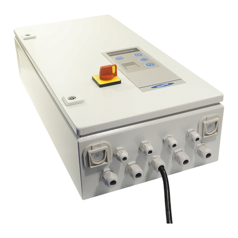
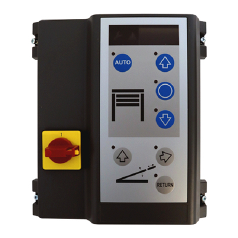
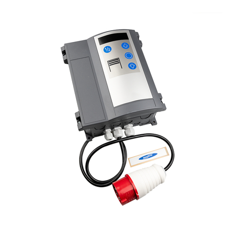
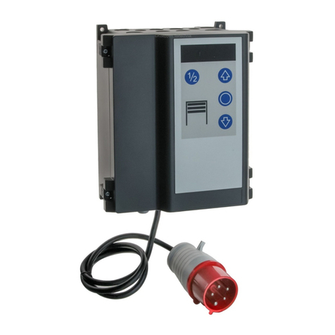
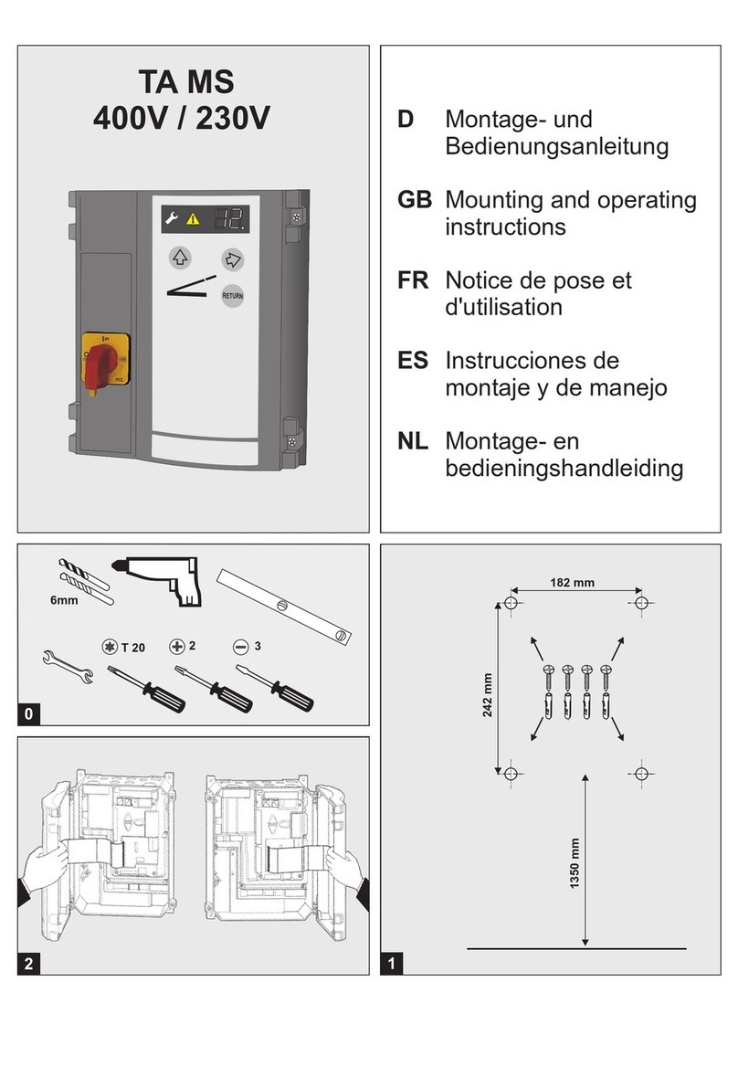
Novoferm HAD MS User manual

HAD MS
400V/230V
Software Release R1.20
Inhaltsverzeichnis
• Allgemeine Informationen
• Installation und
Programmierung der Steuerung
• Bedienungsanleitung und
Funktionsbeschreibung
• Wartung / Überprüfung
• Fehlerdiagnose
• Prüfbuch
- Sicherheit
- Symbolerklärung
- Arbeitssicherheit
- Gefahren, die vom Produkt ausgehen können
- Sicherheitsrelevante Vorschriften
- Ersatzteile
- Veränderungen und Umbauten am Produkt
- Typenschild
- Verpackung
- Technische Daten
- Prüfung der Toranlage
- Prüfliste der Toranlage
- Prüfungs- und Wartungsnachweise der
Toranlage
• Allgemeine Informationen
• Sicherheit
• Symbolerklärung
• Arbeitssicherheit
• Gefahren,
die vom Produkt ausgehen können
• Sicherheitsrelevante Vorschriften
Folgende Vorschriften müssen Sie beachten:
Europäische Normen
Vor Beginn sämtlicher Arbeiten am Produkt die
Betriebsanleitung, insbesondere das Kapitel
Sicherheit und die jeweiligen Sicherheitshinweise,
vollständig lesen. Das Gelesene muss verstanden
worden sein. Es könnten von diesem Produkt
Gefahren ausgehen, wenn es nicht fachgerecht,
unsachgemäß oder nicht bestimmungsgemäß
verwendet wird. Bei Schäden die aufgrund der
Nichtbeachtung dieser Anleitung entstehen, erlischt
die Herstellerhaftung.
WARNUNG: Drohende Gefahr
Dieses Symbol kennzeichnet Hinweise, die
bei Nichtbeachtung zu schweren
Verletzungen führen können.
WARNUNG: Gefahr durch elektrischen
Strom
Die ausführenden Arbeiten dürfen nur von
einer Elektrofachkraft ausgeführt werden.
Dieses Symbol kennzeichnet Hinweise, die
bei Nichtbeachtung zu Fehlfunktionen oder
und/oder Ausfall des Antriebes führen
können
Verweis auf Text und Bild
Durch Befolgen der angegebenen Sicherheits-
hinweise und Anweisungen in dieser Betriebs-
anleitung können Personen- und Sachschäden
während der Arbeit mit und an dem Produkt
vermieden werden.
Bei Nichteinhaltung der angegebenen Sicherheits-
hinweise und Anweisungen in dieser Betriebsan-
leitung sowie die für den Einsatzbereich geltenden
Unfallverhütungsvorschriften und allgemeinen
Sicherheitsbestimmungen sind jegliche Haftpflicht-
und Schadenersatzansprüche gegen den Her-
steller oder seinen Beauftragten ausgeschlossen.
Das Produkt wurde einer Gefährdungsanalyse
unterzogen. Die darauf aufbauende Konstruktion
und Ausführung des Produktes entspricht dem
heutigen Stand der Technik.
Das Produkt ist bei bestimmungsgemäßer
Verwendung betriebssicher. Dennoch bleibt ein
Restrisiko bestehen!
Das Produkt arbeitet mit hoher elektrischer
Spannung. Vor Beginn der Arbeiten an elektrischen
Anlagen ist folgendes zu beachten:
1. Freischalten
2. Gegen Wiedereinschalten sichern
3. Spannungsfreiheit feststellen
Bei der Installation, Inbetriebnahme, Wartung und
Prüfung der Steuerung müssen die örtlichen
Schutzbestimmungen eingehalten werden!
- DIN EN 1398
Ladebrücken–Sicherheitsanforderungen
- DIN EN 12445
Nutzungssicherheit kraftbetätigter Tore
Prüfverfahren
- DIN EN 12453
Nutzungssicherheit kraftbetätigter Tore
Anforderungen
!
0
- DIN EN 12978
Schutzeinrichtungen für kraftbetätigte Tore
Anforderungen und Prüfverfahren
Zusätzlich müssen die normativen Verweise der
aufgeführten Normen beachtet werden.
- DIN EN 418
Sicherheit von Maschinen
NOT-AUS-Einrichtung, funktionelle Aspekte
Gestaltungsleitsätze
- DIN EN 60204-1 / VDE 0113-1
Elektrische Anlagen mit elektrischen
Betriebsmitteln
- DIN EN 60335-1 / VDE 0700-1
Sicherheit elektrischer Geräte für den
Hausgebrauch und ähnliche Zwecke
Nur Original-Ersatzteile des Herstellers
verwenden. Falsche oder fehlerhafte
Ersatzteile können zu Beschädigungen,
Fehlfunktionen oder Totalausfall des Produktes
führen.
Zur Vermeidung von Gefährdungen und zur
Sicherung der optimalen Leistung dürfen am Pro-
dukt weder Veränderungen noch An- und Umbau-
ten vorgenommen werden, die durch den Hersteller
nicht ausdrücklich genehmigt worden sind.
Das Typenschild befindet sich seitlich am Steuer-
ungsgehäuse. Die angegebenen Anschlusswerte
sind zu beachten.
Entsorgung der Verpackungsmaterialien stets
umweltgerecht und nach den geltenden örtlichen
Entsorgungsvorschriften vornehmen.
Abmessungen Gehäuse
Höhe x Breite x Tiefe 250mm x 215mm x 120mm
Montage senkrecht
Kabeldurchführungen 6 (4)x M20
2 x M16
2 x M20 V-Ausschnitt
Versorgungsspannung 3 x 400 V AC
3 x 230 V AC
Steuer-Spannung 24 V DC
Motorleistung
Torantrieb: max. 1,5 kW
Hydraulikmotor: max. 1,5 kW
Schutzklasse IP 65
Betriebstemperatur - 20°C bis + 55°C
VDE-Vorschriften
• Ersatzteile
• Veränderungen und Umbauten am Produkt
• Typenschild
• Verpackung
Technische Daten
Beschädigte Netzanschlussleitungen,
Transformatoren und Leiterplatten dürfen nur vom
Hersteller oder qualifizierten Personen ersetzt
werden.
Diese Montage-, Bedienungs- und Wartungsanleitung ist während der gesamten Nutzungsdauer aufzubewahren!
D
AUTO
RETURN
WN 908002-35-6-50 09/12

Installation
Für allpoliges Trennen der Netzspannung
ist ein Hautschalter installiert.
Bei Reparatur- und Wartungsarbeiten ist
der Hauptschalter gegen unbefugtes oder
irrtümliches Einschalten zu sichern.
N e b e n d e m Ve n t i l a n s c h l u s s k a n n d e r
Klappkeilsensor für die Funktion automatische
Rückkehr angeschlossen werden.
Brücke entfernen und Not-Aus-Taster anschießen.
Bei Unterbrechung stoppt die Überladebrücke, keine
Schwimmstellung.
Erforderlich bei Kombibetrieb mit gegenseitiger
Verriegelung (Menü 17=0). Nur in Ruhelage kann
das Tor geschlossen werden.
br - braun
bk - schwarz
bl - blau
Anschlussmöglichkeit für einen Radkeilsensor.
Auswahl Menü 15 = 1.
Nur bei positionierten Radkeil kann die Überlade-
brücke heben und ausfahren.
br - braun
gr - grau
bk - schwarz
Bei Verwendung eines Schlüsselschalter /
Benötigte Werkzeuge
Montage Steuerung
Öffnen der Steuerungsabdeckung
Hauptschalter
Ventilanschluß
Not-Aus-Taster
Sensor Ruhelage
Radkeil
Anschluss Schlüsselschalter / Zugschalter
Anschlüsse
Benennung:
Netzanschluss
4a
Anschluss Hydraulikmotor
J1 Start / Impuls-Eingang (AUF / HALT / ZU)
J2 Sicherheitslichtschranke 2- oder 4-Draht
J3 Schließkante OSE / 8K2 / DW
J4 Notaus, Schlaffseil, Verriegelung
J5 Endschalter Ruhelage
J6 Radkeil
J7 Schlüsseltaster / Zugschalter
J9 Digitaler Endschalter - Motorkabel
J10 Anschluss Erweiterungssteuerungen
J11 Anschluss Funkempfänger
J12 Antenne
J13 Folientastatur
J14 Kommunikationsschnittstelle
X1 Netzanschluss
X2 Netzausgang L, N (500 W / 230 V)
X3 Schutzleiterkontakt
X4 Hydraulikpumpe
X5 Potentialfreier Relaisausgang 1,
Torstatusrelais
X6 Potentialfreier Relaisausgang 2,
Torstatusrelais
X7 Torantrieb
X8 Hydraulikventile, Sensoren
Die Steuerung ist mit einem CEE-Stecker 16A und
ca. 1m Kabel anschlussfertig entsprechend
verdrahtet.
Ein falscher Anschluss der Netzspannung
kann zu einem Defekt der Steuerung führen.
Drehfeld beachten.
!
0
1
2
3
4
5
6
7
8
9
Zugschalters ist im Menü 50 die gewünschte
Funktion auszuwählen.
2 Wechslerkontakte max. belastbar: 250VAC / 2A
oder 24VDC / 1A.
Der 24V-Ausgang an X8 darf max. mit 100mA
belastet werden.
Die Relaisfunktion ist in den Menüs 45 und 46
auszuwählen.
Relaisausgänge
Motoranschluss
Motoranschlussleitung
Anschluss für Impulsgeber
13b
13d
Anschluss für Lichtschranke
14a
14b
14c
Anschluss für Schließkantensicherung
15a
15b
15c
15d
Funkfernsteuerung
Motoranschluss nach vorliegender Netzspannung
durchführen. Vergleiche auch mit Bild 4.
Die Anschlussleitung ist für Motor und digitalen
Endschalter DES vorkonfektioniert -Austecken.
Soll das Tor über einen Taster geöffnet und
geschlossen werden (Auf-Halt-Zu), so ist zu wählen:
in Menü 51 den Wert 1 einstellen oder
Menü 50, Werkseinstellung
Im Menü 36 muss die Lichtschranke entsprechend
eingestellt werden.
2-Drahtlichtschranke LS2
Dabei darf die Schließfahrt nicht gestört
werden, um keine falsche Position zu
erfassen.
4-Drahtlichtschranke LS5 mit Testung
Reflexionslichtschranke RLK29
Wenn im Menü die Lichtschranke in der Zarge
montiert ausgewählt wurde, führt die Steuerung bei
der nächsten Fahrt in Zu eine Lernfahrt zur
Positionserkennung durch.
Bei Impulsbetrieb Zu ist eine Schliesskanten-
sicherung anzuschliessen. Entsprechende im Menü
35 auswählen.
optische Schießkantensicherung OSE
elektrische Schließkantensicherung 8K2 mit
8,2 KOhm Abschlusswiderstand
elektrische Schließkantensicherung 8K2 in
Reihenschaltung mit Schlaffseil- und
Schlupftürschalter
Druckwellenleiste und -Schalter mit
8,2 KOhm Schleifenwiderstand
Empfängermodul (Option) auf J11 aufstecken und im
Menü 60 oder 62 Handsender einlernen.
10
11
12
13
14
15
16
Programmieren der
Steuerung
Die Programmierung ist menügesteuert. Alle
Einstellungen bitte entsprechend dem Schema
durchführen.
Wenn die Einstellungen geschützt sind, erscheint im
Display ein und der Zugang ins Menü ist gesperrt.
Um das Menü freizugeben muss mit der IR-
Fernbedinung das Freigabesignal gegeben werden.
(Menü 10)
Wird der eingestellte Stromwert überschritten
schaltet die Steuerung die Pumpe ab.
Vorab heben Sie die Ladebrücke so lange an, bis das
Überdruckventil anspricht. Im Menü 10 die Taste für
5 Sekunden gedrückt halten, der erreichte Wert für
den Motorstrom wird jetzt angezeigt. Stellen Sie
sicher, dass der eingestellte Wert größer ist.
(Menü 13)
Für die eingestellten Zeit wird die Überladebrücke
nach Betätigung der Returntaste angehoben um
anschließend sicher in die Ruhelage zu sinken.
(Menü 17)
(Menü 42)
Gleicht Veränderungen der Zuposition aus, die durch
Temperatur, Einlaufen des Getriebes usw. herrühren.
(Menü 43)
Gleicht Veränderungen der Zuposition aus, die durch
Seillängung bzw. durch Anheben des Fußbodens
entstehen.
Zuvor erst genaue Zuposition einstellen, anschlies-
send Menü 43 einstellen.
In den Einstellungen 2, 3 und 4 werden die
eingelernten Positionen aus Menü 31, 34 und 37
entsprechend angepasst.
(Menü 47)
Bei Überschreitung des eingestellten Wertes wird
Fehler E32 angezeigt.
Nach dem Erneuern der Federn sind die
Torendlagen neu einzustellen.
Motor 9.24/5.24: Eingabewert = U x Gewicht / 20Kg
Motor 9.20: Eingabewert = U x Gewicht / 16Kg
Motor 9.15: Eingabewert = U x Gewicht / 15Kg
Motor 9.24, U = 8 Umdrehungen für Toröffnung
Torblattgewicht = 150Kg, bei 2 Federn trägt jede
75Kg. DieAbschaltung soll bei 60Kg erfolgen.
= 8 x 60Kg / 20Kg =
Einstellung ist bei Schnellentriegelung
erforderlich, andernfalls sind Federbruch-
schalter anzuschließen.
Nachdem das Tor einmal komplett auf und zuge-
fahren wurde, Menü 47 anstatt kurz, die Taste 5
Sekunden lang drücken.
Wert gibt an, wie das Tor ausbalanciert ist:
Motor 9.24/5.24: F (Kg) = Anzeigewert x 20Kg / U
Motor 9.20: F (Kg) = Anzeigewert x 16Kg / U
Motor 9.15: F (Kg) = Anzeigewert x 15Kg / U
U = Anzahl der Umdrehungen für eine Toröffnung
Wenn Anzeigewert -2 bis -9, dann sind Federn zu
stark gespannt.
Die Ergebnisse sind nur annäherungsweise zu
betrachten. Zur genaueren Bestimmung ist eine
Kraftmessfahrt durchzuführen.
L
Überstom Hydraulikmotor
Anzeige Istwert
Automatikzeit
Betriebsmöglichkeiten Überladebrücke-Tor
Nachlaufwegkorrektur
Bodenanpassung
Federbrucherkennung
Beispiel:
Eingabewert 24
Prüfung Federausgleich
!
!
Die Steuerung ist für die erste Inbetriebnahme in
Menü 17 = 4 auf Betrieb Überladebrücke eingestellt.
Sobald das Tor in Betrieb genommen wird, ist die
entsprechende Funktion einzustellen.
Achten Sie darauf, dass Tor und Überlade-
brücke sich gegenseitig nicht beschädigen
können.
D

Bei Verwendung von 6.65DU weicht die
Funktion ab. Hierzu bitte denAbschnitt
“Funktion DU”berücksichtigen.
!
Öffnungskraftbegrenzung
Kraftmessfahrt
0
1
Funk Handsender einlernen
Auswahl Steuerungstyp
Startimpuls
(Menü 48)
Die Öffnungsfahrten werden mit der vorherigen Fahrt
verglichen. Bei Überschreitung mit dem eingestellten
Wert stoppt das Tor und F33 erscheint.
Das Tor kann anschließend nur im Totmann-
betrieb zugefahren werden. Ursache der
Kraftüberschreitung beseitigen und danach das
Tor auf und zufahren.
Motor 9.24/5.24: Eingabewert = U x Gewicht / 20Kg
Motor 9.20: Eingabewert = U x Gewicht / 16Kg
Motor 9.15: Eingabewert = U x Gewicht / 15Kg
Die Ergebnisse sind nur annäherungsweise zu
betrachten. Zur genaueren Bestimmung ist eine
Kraftmessfahrt durchzuführen.
Bei Verwendung von 6.65DU weicht die
Funktion ab. Hierzu bitte denAbschnitt
“Funktion DU”berücksichtigen.
zur Bestimmung der Abschaltschwelle.
Nach Eingabe des Wertes 99 im Menü 48 führt die
Steuerung eine Kraftmessfahrt durch:
1. Ein Prüfgewicht (empfohlen ca. 20Kg) am Tor
befestigen und Tor komplett auf und zufahren.
2.Anschließend erscheint im Menü 48 der Wert
und wird alsAbschaltwert übernommen. Der
Wert kann geändert werden (doppelter Wert
gleich doppelte Kraft).
3. Prüfgewicht wieder entfernen und Tor wieder auf
und zufahren.
51)
Eingang J1.3 wurden für Inpulsgabe ZU
Eingang J1.4 für Impulsgabe AUF
verwendet.
Das Tor muss von dem Ort der
Bedienung aus einsehbar sein.
Der Eingänge werden für Impulsgabe
Auf-Halt-Zu verwendet. J.1.3 für ½ Toröffnung
J1.4 für die volle Toröffnung.
Bitte beachten Sie, dass jeder Handsender für sich
eingelernt werden muss. Sie haben die Möglichkeit
30 Funkcodes einzulernen. Folgende Funktionen
sind einlernbar:
KeeLoq, 12 Bit Multibit. Der erste Code bestimmt den
Typ.
(Menü 59)
In Menü 59 werden verschiedene Steuerungstypen
ausgewählt. Entsprechende Einstellungen sind den
Zusatzblättern zu entnehmen.
(Menü 60)
Gehen sie ins Menü und betätigen Sie die Taste des
Handsenders für die Startfunktion. Sobald der Code
eingelernt ist blinkt die P
!
!
Einschaltdauer
RWA-Funktion (Rauch-Wärme-Abzug)
externe Befehlsgeräte / Impulsgeber
Lichtfunktion
(Menü 49)
Die eingestellte Einschaltdauer verhindert die
Überhitzung des Antriebsmotors und vermeidet
Schäden.
Bei Einsatz des Motors 5.24 mit Kunststoff-
getriebe muss die Einschaltdauer auf 1 (3~) oder
auf 2 (WS, 1~) eingestellt werden.
Im Menü 55 die entsprechende Torposition
einstellen. Brandmeldeanlage an J7 anschließen
und im Menü 50 Wert 7 einstellen.
(Menü
unktanzeige im Display 5
mal.
(Menü 62)
Gehen sie ins Menü und betätigen Sie die Taste des
!
Handsenders für die Lichtfunktion. Sobald der Code
eingelernt ist blinkt die Punktanzeige im Display 5
mal.
(Menü 63)
Um einen sicheren Betrieb der Überladebrücke zu
gewährleisten, muss die Erstinbetriebnahme von
sachkundigem Personal erfolgen.
- Stellen Sie den Hauptschalter ein
- Führen Sie einen Probelauf durch, indem Sie
alle Bedienfunktionen ausführen
Wenn alle Bedienfunktionen einwandfrei
durchgeführt werden können, ist die Überladebrücke
betriebsbereit.
Erstinbetriebnahme
Funkcodes löschen
DU Funktionen
Zum Löschen aller eingelernter Codes im Menü
ovale Taste für 5 Sekunden gedrückt halten.
(Hauptmenü 7)
Bei der Erstinbetriebnahme ist die Steuerung in
Menü 99 auf Werkseinstellungen zurückzusetzen.
Die Funktion “Öffnungskraftbegrenzung”im DU
kann im Menü 48 ausgewählt werden:
Wert = 0, Kraftbegrenzung aus
Wert = 1 - 99, Kraftbegrenzung ist aktiviert
Um den Antrieb gegen Überhitzung zu schützen,
muss die Einschaltdauer im Menü 49 auf 5
eingestellt werden.
!
Betriebsanleitung /
Funktionsbeschreibung
Betrieb der Überladebrücke
In diesem Kapitel beschreiben wir Ihnen den
kompletten Betrieb der Überladebrücke. Um ein
sicheres Arbeiten mit diesem Produkt zu
gewährleisten, ist es unbedingt erforderlich, dass Sie
die folgenden Sicherheits- und Gefahrenhinweise
befolgen.
Alle Personen, die die Überladebrücke bedienen,
müssen vorher eingewiesen worden sein. Der
Betreiber muss gewährleisten, dass alle Personen
die Einweisung verstanden haben.
Das Personal muss außerdem die Gebrauchs- und
Bedienungsanleitung aufmerksam gelesen und
verstanden haben. Das selbstständige Bedienen ist
nur unterwiesenen Personen und Personen mit
einem Mindestalter von 18 Jahren erlaubt.
1. Beachten Sie die Bewegungen der
Überladebrücke!
2. Während des Hebens und Senkens der
Überladebrücke dürfen sich keine Personen im
Bewegungsbereich der Überladebrücke
aufhalten.
3. Während des Verladens muss der Haupt-
schalter immer in Position I stehen.
Beim Verladebetrieb werden sonst die Höhen-
bewegungen des LKW von der Überladebrücke
nicht mitgemacht.
4. Stellen Sie in Notfällen den gelb-roten
Hauptschalter auf 0. Jede Bewegung der
Überladebrücke ist dann unterbrochen,
wenn Sie:
a) den Hauptschalter betätigen oder
b) die Stromversorgung unterbrechen oder
c) Not-Aus-Taster betätigen.
Der Verladevorgang muss abgebrochen werden
siehe Wiederanlaufsperre.
5. Vor der täglichen Inbetriebnahme muss die
Überladebrücke aus Sicherheitsgründen einer
Sichtprüfung unterzogen werden:
Wenn keine Beanstandungen vorliegen, können
Sie die Überladebrücke in Betrieb setzen.
Stellen Sie den Hauptschalter ein und betätigen
Sie kurz den Taster Heben.
Die Überladebrücke ist jetzt betriebsbereit.
Wenn Sie den Taster gedrückt halten, hebt sich
die Überladebrücke an.
Gleichzeitig schwenkt im oberen Arbeitsbereich der
Überladebrücke der Klappkeil aus.
Nach Loslassen des Tasters senkt sich die
Überladebrücke automatisch ab.
Nach Loslassen der Taste Heben , senkt sich die
Überladebrücke mit dem Auflager auf den LKW ab
und befindet sich in der Schwimmstellung. Die
Überladebrücke folgt den Höhenbewegungen des
LKWs.
Nach dem Wiedereinschalten des Hauptschalters
oder des Not-Aus-Tasters ist die Wiederanlauf-
sperre aktiv, die gelbe Warnanzeige blinkt im
Display.
Das Befahren der Überladebrücke ist in
diesem Fall verboten.
Wenn der Verladevorgang beendet ist, können Sie
durch Betätigen der Taste RETURN die
Überladebrücke zurück in die Ruhelage fahren.
Die Überladebrücke hebt an und senkt sich
anschließend ohne Tasterbewegung selbständig bis
auf Laderampenhöhe ab.
Heben
Schwimmstellung
Wiederanlaufsperre
Return / Überladebrücke in Ruhelage
Autotaster
(optional)
Beleuchtung und / oder Vorwarnlicht (optional)
Ladeleuchte (optional)
Sicherheitsradkeil (optional)
Funktion Schlüsselschalter (optional)
0
1
2
3
4
5
Durch kurzes Antippen der Taste AUTO fährt die
Überladebrücke automatisch in die Ruhestellung
zurück und das Tor schließt anschließend ohne
weiterer Tasterbetätigung selbstständig in die
Zuposition (nur möglich in ImpulsbetriebAuf / Zu).
Die Steuerung verfügt über 2 Relaisausgänge mit
denen Verladeleuchte und / oder Rot-Grün-Ampel
geschaltet werden kann (Menü 45 und 46).
Wenn das Tor die Offenstellung erreicht, schaltet die
Ladeleuchte ein. Sobald das Tor wieder die
Offenposition verlässt, schaltet die Ladeleuchte aus.
Nur wenn der Radkeil hinter dem LKW-Reifen
positioniert ist, kann die Überladebrücke Heben und
Ausfahren.
Die Steuerung besitzt einen Eingang für einen
Schlüsselschalter. Sie haben damit die Möglichkeit,
folgende Funktionen (Menü 50) zu aktivieren:
Impulsgeber mit SchaltfolgeAuf-Halt-Zu.
Bedienfeld der Steuerung wird gesperrt.
alle externen Bedienelemente werden gesperrt.
Bedienfeld der Steuerung und alle externen
Bedienelemente werden gesperrt.
Für 10 Sekunden sind Bedienfeld der Steuerung
und alle externen Bedienelemente aktiv.
Umschaltung der Betriebsart in Impuls Auf /
Totmann Zu
Selbstätige Rückkehr
Nach Wegfahren des LKWs startet die Überlade-
brücke selbstätig in die Ruhestellung und das Tor
fährt zu.
Diese Funktion ist nur möglich in Verbindung mit
entsprechenden Sensoren. Weiterhin muss ein
optisches und akustisch Signal muss installiert sein.
!
D
6
7
Totmann Auf / Totmann Zu
ImpulsAuf / Totmann Zu
ImpulsAuf / Impuls Zu
Funkhandsender (optional)
Eingang J7 für Impulsgeber mit Schaltfolge Auf-
Halt-Zu
RWA-Funktion (Rauch-Wärme-Abzug)
Im Menü 55 die entsprechende Torposition
einstellen. Brandmeldeanlage an J7 an-
schließen und im Menü 50 Wert 7 einstellen.
Die Steuerung ermöglicht unterschiedliche
Betriebsarten:
Durch Dauerdruck auf die Taste startet der Torlauf
in Richtung Auf, bis Torendlage Auf erreicht ist, oder
durch Loslassen der Taste der Torlauf gestoppt wird.
Ein Schließen des Tores erfolgt über Dauerdruck
(Totmann-Funktion) der Taste , bis Torendlage
erreicht ist. Wird dieTaste während des Zulaufes
losgelassen, stoppt das Tor sofort.
Durch kurzen Druck auf die Taste oder externe
Impulsgeber startet der Torlauf in Richtung Auf bis
Torendlage Auf erreicht ist, oder durch Tastendruck
auf gestoppt wird. Ein erneuter Tastendruck auf
Taste setzt die Öffnungsfahrt fort. Ein Schließen
des Tores erfolgt über Dauerdruck (Totmann-
Funktion) der Taste , bis Torendlage erreicht ist.
Wird die Taste während des Zulaufes
losgelassen, stoppt das Tor sofort.
Ein kurzes Betätigen der Taste oder externer
Impulsgeber startet den Torlauf in Richtung Auf bis
Endlage Auf erreicht, oder durch Taste gestoppt
wird. Ein kurzes Betätigen der Taste startet den
Torlauf in Richtung Zu bis Endlage Zu erreicht ist.
Diese Betriebsart verlangt die Installation einer
Schießkantensicherung (Menü 35).
Bei einem Defekt kann
das Tor durch geschlossen werden.
Taste Start:
Taste Licht:
Bei der Lichtfunktion handelt es sich um ein
Dauerlicht, welches unabhängig vom Torlauf
„Ein/Aus“geschaltet werden kann.
Torbetrieb
Ein Auslösen der Schließkantensicherung bewirkt
während der Schließfahrt ein Stoppen und eine
Richtungsumkehr. Während der Öffnungsfahrt hat
dasAuslösen keinen Einfluss.
Antrieb startet und fährt Tor in die eingestellte
EndpositionAUF oder ZU.
Tor stoppt.
Tor setzt in entgegengesetzter Richtung den Lauf
fort.
Erste Impulsgabe:
Impulsgabe während der Fahrt:
Erneuter Impuls:
Wartung / Überprüfung
Die Überladerbrücke und Toranlage
muss bei der Inbetriebnahme und nach
Bedarf - jedoch mindestens einmal
jährlich - von einem Fachbetrieb
prüfen zu lassen.
Serviceanzeige
Stellt die Steuerung Bedarf für eine Überprüfung fest,
leuchtet die Serviceanzeige im Display auf.
Fachbetrieb informieren.
D

1x
3-9 30-
37
Exit
EnterMenü Item
D
Auswahl
Radkeil
ohne Radkeil
mit Radkeil
Menü beenden
ohne Radkeil
mit Radkeil
Überstrom Motorpumpe
2,6 A
3,2 A
3,8 A
4,4 A
5,0 A
5,6 A
6,2 A
6,8 A
7,4 A
8,0 A
8,6 A
9,2 A
0,0 A
Automatikzeit
3 s
5 s
7 s
9 s
11 s
13 s
15 s
20 s
30 s
25 s
Kombibetriebsarten
gegenseitige Verriegelung Tor - Ladebrücke
ohne Verriegelung Tor - Ladebrücke
Verriegelung Ladebrücke bei nicht geöffneten Tor
nur Ladebrückenbetrieb
nur Torbetrieb
Verriegelung Ladebrücke ohne SensorTor -
aufblasbare Torabdichtung
aus
Torabdichtung
Ausschaltverzögerung in Position Tor Zu
0* = 0 s ; 1 = 5 s ; 2 = 10 s ; 3 = 15 s ; 4 = 20 s
Verzögerungszeit Tor öffnen
Menü beendenMenü beenden
5 = 25 s ; 6 = 30s; 7 =35 s; 8 = 40 s
9 = 45 s ; 10 = 50 s ; 11 = 55 s ; 12 = 60 s
0* = 0 s ; 1 = 5 s ; 2 = 10 s ; 3 = 15 s ; 4 = 20 s
5 = 25 s ; 6 = 30s; 7 =35 s; 8 = 40 s
9 = 45 s ; 10 = 50 s ; 11 = 55 s ; 12 = 60 s
Nr.
1
Ein-
gabe
Menü-
Punkt
0*
1
15
Grundeinstellungen Ladebrücke
Nr.
1
Menü-
Punkt
0*
1
15
- -
Grundeinstellungen Überladebrücke
10
2
3
4*
5
6
1
7
8
9
10
11
12
0
0
1*
2
3
4
5
6
7
9
13
8
0
1
3
17
4*
5
2
1
0*
21
0 - 4
20
2
22
Torabdichtung
- -- -
4 - 8
9 - 12
0 - 4
4 - 8
9 - 12
Programmierübersicht
* Werkseinstellung
Bodenanpassung
ein
aus
Nachlaufwegkorrektur
Teilreversieren
Vollreversieren
Reaktion auf Schließkantensicherung
Impuls Auf / Impuls Zu
Impuls Auf / Totmann Zu
Totmann Auf / Totmann Zu
Wahl Betriebsart
0... 100mm höher
0... 50mm tiefer
Korrektur Vorendschalter Schließkantensicher.
4-Drahtlichtschranke LS5, Reflexionslichts.
2-Drahtlichtschranke LS2
ohne Lichtschranke
Auswahl Lichtschranke
Meßwertanzeige (5 Sek. drücken)
Auswahl Schließkantensicherung
0... 80mm höher
0... 80mm tiefer
Feinkorrektur obere Endlage
Toreinstellung untere Endlage
Richtungsumkehr (5 Sek. drücken)
Toreinstellung obere Endlage
Auswahl
1*
0
1
0*
2*
1
0
25 - 99
25 - 0
25*
2
1
0*
Nr.
3
Tor - Grundeinstellungen
we it er e Toreins te llungen
50 - 99
50 - 0
50*
Ein-
gabe
40
37
36
33
31
30
Menü-
Punkt
0... 80mm höher
0... 80mm tiefer
Feinkorrektur untere Endlage
50 - 99
50 - 0
50*
34
41
42
35
Lichtschranke LS5, Reflexionsl. in Zarge montiert4
43
1
0*
2
Vorendstop durch Schließkante
aus
Bodenanpassung für 200 Zyklen aktiviert
4
Menü beenden
- -
Druckwellenleiste mit Testung
elektrische Schaltleiste 8K2
optische Schliesskantensicherung OSE
2
1*
0
elektrische Schaltleiste 8K2 mit Schlaffseilschalter
3
4 permanente Bodenanpassung
3 Bodenananpassung für 1000 Zyklen aktiviert
4-Drahtlichtschranke LS5, mit Stoppfunktion in Auf6
Lichtschranke LS2 in Zarge montiert3
2-Drahtlichtschranke LS2, mit Stoppfunktion in Auf5

1x
3-9 30-
37
Exit
EnterMenü Item
D
Programmierübersicht
Menü beenden
Funkcodes löschen (5 Sek. drücken)
Handsender Lichttaste einlernen
Handsender Starttaste einlernen
Menü beenden
Eingabe Steuerungsadresse
Bedienelemente für 10 Sekunden aktivieren
Bedienfeld und externe Bedienelemente sperren
externe Bedienelemente sperren
Bedienfeld sperren
Impulseingang Auf/Zu
Funktion Schlüsselschalter (J7)
Auswahl
4
3
2
1
0*
Ein-
gabe
52
50
- -
Menü-
Punkt
Nr.
6
- -
60
62
63
- -
Funk
5
diverse Einstellungen
Menü beenden
Auswahl
Ein-
gabe
Menü-
Punkt
Nr.
4
Wischimpuls ELTACO
ein / aus Handsender
5 Minuten Garagenlicht
2 Minuten Garagenlicht
Tor-Auf-Meldung / Verladeleuchte
Tor-Zu-Meldung
Statusrelais X5
5
4
3
2
1
0*
45
weitere Toreinstellungen
Signal für selbsttätige Rückkehr
6
001-256
Modul Toransteuerung
aus
0*
Ansteuerungsprofile siehe Modul Toransteuerung
1, 2, 3
53
Erweiterungssteuerung
aus
0*
Ansteuerungsprofile siehe Erweiterungsteuerung
1, 2, 3
54
Eingabe Federkraft
aus
Federbrucherkennung
1 - 99
0*
47
Eingabe Abschaltkraft
aus
Öffnungskraftbegrenzung
1 - 98
0*
48
4
2
Motoreinschaltdauer
1
0*
49
5
6
3
Anzeige Federausgleich (5 Sek. drücken)
Gewichtsmessfahrt mit Prüfgewicht durchführen99
Getriebemotor 14.15 25Min / 60%
Getriebemotor 9.15, 9.20, 9,24 25Min / 60%
Getriebemotor 5.24 25Min / 35%
ohne Begrenzung
Getriebemotor 9,24 WS 25Min / 20%
Getriebemotor 5.24 WS 25Min / 30%
Getriebemotor 6.65 DU 10Min / 35%
Umschalten in Totmann Zu
5
Toreinstellung RWA
55
diverse Einstellungen
* Werkseinstellung
3 Sekunden vor ZufahrtVorwarnzeit
Rotampel ohne Vorwarnzeit
3
2
Tor-Auf-Meldung
Tor-Zu-Meldung
Statusrelais X6
1
0*
46
3 Sekunden Vorwarnzeit vor Auf- und Zufahrt
4
Auf-Halt-Zu Funktion (J1.3 1/2-, J1.4 Vollöffnung)
Funktion externe Impulsgeber J1
1
51 Dreiknopfsteuerung
0*
Impulseingang AUF-Halt-Zu
6
Impulseingang für RWA (Einstellung in Menü 55)
7
7
DU- Einstellungen
71
72
73
74
75
76
77
78
- -
Erhöhte Schließgeschwindigkeit
Drehzahl in Umdrehungen / Min.
Schließgeschwindigkeit
Drehzahl in Umdrehungen / Min.
Öffnungsgeschwindigkeit
0*
20 - 30
20*
20 - 65
30*
Toreinstellung Umschaltpunkt auf[73] [72]
Drehzahl in Umdrehungen / Min.20 - 30
Beschleunigungszeit Zu
x 0,1Sek.
Beschleunigungszeit Auf
20*
05 - 30
20*
x 0,1Sek.05 - 30
Bremszeit Zu
x 0,1Sek.
Bremszeit Auf
20*
05 - 30
20*
x 0,1Sek.05 - 30
Menü beenden

Ausgabe Zyklenzähler Torantrieb Zyklen- -
50000 Zyklen
45000 Zyklen
40000 Zyklen
35000 Zyklen
30000 Zyklen
25000 Zyklen
20000 Zyklen
16000 Zyklen
12000 Zyklen
8000 Zyklen
4000 Zyklen
1000 Zyklen
kein Serviceintervall
Vorwahl Wartungszyklus Torantrieb
12
11
10
9
8
7
6
5
4
3
2
1
0*
91
Ausgabe Zyklenzähler Ladebrücke Zyklen- -
6000 Zyklen
5500 Zyklen
5000 Zyklen
4500 Zyklen
4000 Zyklen
3500 Zyklen
3000 Zyklen
2500 Zyklen
2000 Zyklen
1500 Zyklen
1000 Zyklen
500 Zyklen
Vorwahl Wartungszyklus Ladebrücke
Auswahl
11
10
9*
8
7
6
5
4
3
2
1
0
Ein-
gabe
Menü-
Punkt
92
Nr.
Servicemenü
93
9
90
(5 Sek. drücken)Rücksetzen Werkseinstellung
Ausgabe Softwareversion Serien-Nr. H.-Datum- - -
Stunden FehlercodeAusgabe Fehlerspeicher - - -
StundenAusgabe Betriebsstundenzähler - -
6000 Zyklen
5500 Zyklen
5000 Zyklen
4500 Zyklen
4000 Zyklen
3500 Zyklen
3000 Zyklen
2500 Zyklen
2000 Zyklen
1500 Zyklen
1000 Zyklen
500 Zyklen
Vorwahl Wartungszyklus Torabdichtung
11
10
9*
8
7
6
5
4
3
2
1
0
94
Menü beenden
96
97
98
99
- -
- Zyklen -Ausgabe Zykluszähler Torabdichtung
95
1x
3-9 30-
37
Exit
EnterMenü Item
D
Programmierübersicht
* Werkseinstellung

Fehlerdiagnose
Änderungen vorbehalten
D
Fehler Zustand Diagnose / Abhilfe
E05 Tor fährt weder auf noch zu Schlaffseilschalter hat ausgelöst (siehe Bild 8c)
E06 Tor reversiert / schließt nicht Schließkante hat ausgelöst. Menüeinstellung [35] prüfen.
E07 Tor reversiert / schließt nicht Lichtschranke hat ausgelöst. Menüeinstellung [36] prüfen.
E08 Tor fährt weder auf noch zu Externe Sicherheitseinrichtung (Not-Aus, Schlaffseil, Schlupftür, Motorthermoschalter)
hat angesprochen. Überprüfen (J4).
E09 Tor fährt weder auf noch zu Keine Torendlage eingelernt. Torendlagen Menü [30] [31] einlernen.
E10 Menü 36 auf 3 oder 4 eingestellt Tor komplett auf uns zufahren, damit die Position der Lichtschranken festgestellt wird.
Fehler bei Selbsttestung aufgetreten,
Tor fährt weder auf noch zu
F11 Kurzschluss Ventil 1 Ventil 1, Zuleitung überprüfen.
F14 Unterbrechung Ventil 1 Ventil 1, Zuleitung überprüfen.
F17 Überladebrücke reagiert nicht Störung Hydraulikmotor.
Hydraulikmotor schaltet ab Laufzeitbegrenzung Motorpumpe, Fehlbedienung oder defekter Taster.
auf Startbefehl eine Verbindung zum DES. prüfen.
Interner Test Folientastatur fehlerhaft. Folientastatur tauschen.
Interner Test externe Taster / Schalter fehlgeschlagen.
F27 Torendlage wird nicht erreicht Tormechanik / Motoranschlusskabel überprüfen.
Motor blockiert Evtl. Endlagen nachjustieren Menü [33] / [34].
Fehler in der Spannungsversorgung. Netzseitigen Anschluss überprüfen.
Motor dreht falsch herum Netzphasen wurden getauscht, korrigieren oder neu einstellen.
F31 Tor fährt weder auf noch zu Taste betätigt. Dauerimpuls liegt an. Externe Befehlsgeber (J1) überprüfen.
F32 Tor fährt weder auf noch zu Federbrucherkennung hat angesprochen. Federn überprüfen, ggf austauschen.
Nach dem Erneuern der Federn sind die Torendlagen neu einzustellen.
F33 Tor stoppte in der Auffahrt Öffnungskraftbegrenzung angesprochen. Tor kann nur im Totmannbetrieb zugefahren
werden. Schwergängigkeit oder Blockierung des Tores beseitigen. Federn überprüfen.
Ursache der Kraftüberschreitung beseitigen und danach das Tor auf und zufahren.
F34 Tor fährt weder auf noch zu Einschaltdauer wurde überschritten. Warten und Motor abkühlen lassen.
F35 Tor fährt weder auf noch zu Drehzahlüberwachung hat angesprochen. DU-Antrieb austauschen.
F40 Erweiterungssteuerung 24V zusammengebrochen. Anschlüsse an Erweiterungssteuerung prüfen.
F41 Erweiterungssteuerung Fehler bei Selbsttestung aufgetreten. Erweiterungsteuerung tauschen.
F43 Erweiterungssteuerung Verbindung fehlt.
L Der Zugang in Menü wurde vom Kontakt mit Fachhändler aufnehmen.
autorisierten Fachhändler gesperrt Entsperren des Menüs nur mit Service-Tool möglich.
Lo Steuerung wurde gesperrt Kontakt mit Fachhändler aufnehmen.
Entsperren des Menüs nur mit Service-Tool möglich.
U Der Zugang in Menü wurde vom
autorisierten Fachhändler entsperrt
F01 keine Bewegung Tor / Überladebrücke Netzspannung fehlerhaft, Drehfeld kontrollieren, Drehrichtung ändern.
F2 keine Reaktion Fehler bei Selbsttestung aufgetreten, Steuerung tauschen.
F3 keine Reaktion Steuerung tauschen.
F4 keine Reaktion Steuerung tauschen.
F5 keine Reaktion Steuerung tauschen.
F06 keine Reaktion Schließkantensicherung fehlerhaft, Spannung (J3.3 - J3.1 >12V) überprüfen.
F07 24V Spannung zusammengebrochen. Anschlüsse prüfen.
F09 Hydraulikmotor schaltet ab Stromüberwachung Motorpumpe hat ausgelöst. Menüeinstellung [10] prüfen.
F10 Tor stoppt kurz nach Startbefehl Störung in der Steuerungselektronik. Steuerung tauschen.
F19 Tor fährt nur Totmann in Zu Testung Schließkante fehlgeschlagen. Schließkantensicherung überprüfen.
F20 Tor fährt nur Totmann in Zu Testung Lichtschranke fehlgeschlagen. Lichtschranke überprüfen.
F21 kurzzeitige Bertiebsunterbrechung Laufzeitbegrenzung Torantrieb, Antrieb abkühlen lassen, 20 Min. warten.
F22
F24 keine Reaktion K Motoranschlusskabel und DES
F25 keine Reaktion
F26 keine Reaktion
F28 keine Reaktion auf Startbefehl
F29
F30 Tor fährt nur in Totmannbetrieb zu Rücksprung von Impuls auf Totmann-Steuerung.
Schliesskantensicherung und Lichtschranke prüfen.
________________________________________________________________________________________________________________
________________________________________________________________________________________________________________
________________________________________________________________________________________________________________

Diese Montage-, Bedienungs- und Wartungsanleitung ist während der gesamten Nutzungsdauer aufzubewahren!
Prüfliste der Toranlage
(Ausstattung bei Inbetriebnahme durch Abhaken dokumentieren)
Ausstattung vorhanden zu prüfende
zutreffend Eigenschaften i.O.Bemerkung
1.0 Tor
1.1 Handbetätigung des Tores Leichtgängikeit ________________________
1.2 Befestigungen / Verbindungen Zustand / Sitz ________________________
1.3 Drehpunkte / Gelenke Zustand / Schmierung ________________________
1.4 Laufrollen / Laufrollenhalter Zustand / Schmierung ________________________
1.5 Dichtungen / Schleifleisten Zustand / Sitz ________________________
1.6 Torrahmen / Torführung Ausrichtung / Befestigung ________________________
1.7 Torblatt Ausrichtung / Zustand ________________________
2.0 Gewichtsausgleich / Sicheres Öffnen
2.1 Federn Zustand / Sitz / Einstellung ________________________
2.1.1 Spannköpfe, Lagerböcke Zustand ________________________
2.1.2 Federbruchsicherung Zustand/ Typenschild ________________________
2.1.3 Sicherungselemente Zustand / Sitz ________________________
2.2 Drahtseile Zustand / Sitz ________________________
2.2.1 Seilbefestigung Zustand / Sitz ________________________
2.2.2 Seiltrommeln ________________________2 Sicherheitswindungen
2.2.3 Schlaffseilschalter ________________________Zustand / Sitz / Funktion
2.3 Absturzsicherung Zustand ________________________
2.4 Rundlauf T-Welle Zustand ________________________
3.0 Antrieb / Steuerung
3.1 Antrieb / Zustand / Befestigung Konsole ________________________
3.2 Elektrische Leitungen / Zustand ________________________Anschlüsse
3.3 Notentriegelung Zustand / Funktion ________________________
3.3.1 Schnelle Kette Zustand / Funktion ________________________
3.3.2 Handkurbel Zustand / Funktion ________________________
3.3.3 Schnellentriegelung ________________________Zustand / Funktion
4.0 Quetsch- und Scherstellensicherung
4.1 Kraftbegrenzung stoppt und reversiert ________________________
4.2 Schutz gegen Torblatt ________________________
Anheben von Personen
4.3 bauseitiges Umfeld Sicherheitsabstände ________________________
5.0 sonstige Einrichtungen
5.1 Verriegelung / Schloss Zustand / Funktion ________________________
5.2 Schlupftür Funktion / Zustand ________________________
5.2.1 Schlupftürkontakt Funktion / Zustand ________________________
5.2.2 Türschließer Funktion / Zustand ________________________
5.3 Ampelsteuerung Funktion / Zustand ________________________
5.4 Lichtschranken Funktion / Zustand ________________________
5.5 Schließkantensicherung Funktion / Zustand ________________________
6.0 Dokumentation des Betreibers
6.1 Typenschild / vollständig / lesbar _______________________CE-Kennzeichnung
6.2 Konformitätserklärung vollständig / lesbar ________________________
der Toranlage
6.3 Montage-,Bedienungs-, vollständig / lesbar ________________________
Wartungsanleitungen
3.4 Betätigungseinrichtungen ________________________Zustand / Funktion
Taster / Handsender
3.5 Endabschaltung ________________________Zustand / Funktion
Diese Montage-, Bedienungs- und Wartungsanleitung ist während der gesamten Nutzungsdauer aufzubewahren!

Prüfungs- und Wartungsnachweise der Toranlage
Diese Montage-, Bedienungs- und Wartungsanleitung ist während der gesamten Nutzungsdauer aufzubewahren!
D

HAD MS
400V/230V
Software Release R1.20
Table of contents
• General Information
• Installation
• Programming overview
• Operating instructions / Description of
functions
• Maintenance / Checks
• Error Diagnosis
• Terms of Guarantee
• Inspection log book
- Safety
- Explanation of the symbols
- Working safety
- Hazards that may emanate from the product
- Safety regulations
- Spare parts
- Changes and modifications to the product
- Data plate
- Packaging
- Technical data
- Inspection and Test Log Book for the Door
System
- Check List of the Door System
- Proof of Inspection and Maintenance of the
Door System
GB
AUTO
RETURN
• General Information
!
•
•
•
•
Safety
Explanation of the symbols
Working safety
Hazards that may emanate from the product
•
Before commencing any work on the product,
carefully read through the operating instructions
from start to finish, in particular the section entitled
“Safety”and the related safety advice. It is important
for you to have understood what you have read. This
product could prove hazardous if not used properly
as directed or in accordance with the regulations.
Any damage occurring as a result of non-compliance
with these instructions shall render the manufactu-
rer’s liability null and void.
WARNING: imminent danger
This symbol indicates that instructions are
being given which, if not observed, could
lead to malfunctions and/or failure of the
operator.
WARNING! Danger by electric current
The works may only be executed by an
electrician.
This symbol indicates that instructions are
being given which, if not observed, could
lead to serious injury.
Reference to text and figure
By complying with the safety advice and information
provided in these Operating Instructions, injury to
persons and damage to property whilst working on
and with the product can be avoided.
Failure to observe the safety advice and information
provided in these Operating Instructions as well as
the accident prevention and general safety
requirements relevant to the field of application shall
exempt the manufacturer or ist authorized
representatives from all liability and shall render any
damage claims null and void.
The product has been subjected to a risk assess-
ment. The design and execution of the product
based on this corresponds to state-of-the-art
technology.
When used properly as intended, the product is safe
and reliable to operate.
Nevertheless, a residual risk will always remain!
The product runs on a high electrical voltage. Before
commencing any work on electrical systems, please
observe the following:
1. Disconnect from the power supply
2. Safeguard to prevent a power restart
3. Check that the electricity supply is cut off.
Safety regulations
The following standards and regulations must
be observed:
When performing installation work, initial operation,
maintenance jobs or testing the control unit, take
care to observe the local safety regulations!
European standards
- DIN EN 1398
Dock levellers, safety requirements
- DIN EN 12445
Safety in Use of Power-operated Doors and
Gates - Test Methods
- DIN EN 12453
Safety in Use of Power-operated Doors and
Gates - Requirements
- DIN EN 12978
Protective Devices for Power-operated Doors and
Gates - Requirements and Test Methods
0
In addition to the above, the normative references
of the standards listed must be observed.
- DIN EN 418
Safety of Machinery
Emergency-STOP device, functional aspects
Design principles
- DIN EN 60204-1 / VDE 0113-1
Electrical installations with electrical equipment
- DIN EN 60335-1 / VDE 0700-1
Safety of household and similar electrical
appliances
Dimensions of housing
Height x width x depth 250 x 215 x 120 mm
Mounting vertical
Number of cable lead-throughs 6 (4) x M20,
2 x M16,
2 x M20 V-cutout
Supply voltage 3 x 400 V AC
3 x 230 V AC
Motor power
Door operator max. 1.5 kW
Hydraulic motor max. 1.5 kW
Protection classification IP 65
Operating temperature - 20°C to + 55°C
VDE regulations
•
•
•
•
Spare parts
Changes and modifications to the product
Data plate
Packaging
Only use genuine spare parts of the manufacturer.
Wrong or faulty spare parts can cause
damage, malfunctions or even a total failure
of the product.
In order to prevent hazards and ensure optimum
performance, no changes, modifications or
conversions may be made to the product that have
not been expressly approved by the manufacturer.
The date plate is located under the control panel
cover. Observe the specified power rating.
Always dispose of the packaging in an environ-
mentlly-friendly manner and in accordance with the
local regulations on disposal.
Technical Data
Retain these installation, operating and maintenance instructions for the full duration of the operator’s service life!
WN 908002-35-6-50 09/12

Installation
START / impulse input
(OPEN / STOP / CLOSE)
Safety photocell, two or four-wire
Emergency-STOP, slack cable, latching
Limit switch rest position
Aerial
Protective conductor contact
Hydraulic valve
Floating relay output
The control unit comes ready-wired with a 16A CEE
phase-changer plug and approx. 1 m of cable (see ).
Wrong connection of mains voltage
A mains isolator is provided for
disconnection of all poles of the mains
voltage. Secure the mains isolator against
unauthorised use during maintenance
or repair.
A sensor and limit switch for the automatic return
function can be installed besides the valve
connection.
Remove the jumper and connect the emergency stop
button. Pressing the emergency stop button stops
the dock leveller, no free floating position.
Required for combined operation with mutual
interlocking (menu 17=0). The door can only be
closed at zero position.
br - brown
gr - grey
bk - black
Possible connection of a wheel chock sensor.
Selection of menu 15 = 1.
The dock leveller can only lift and extend when the
wheel chock is applied.
br - brown
gr - grey
bk - black
When using a key switch / pull button, the desired
function in menu 50 should be selected.
Required tools
Installing the control unit
Opening the control unit cover
4a
Mains isolator
Connection of hydraulic motor
Valve connection
Emergency stop button
Sensor zero position
Wheel chock
Key switch / pull button connection
Connections
Designation:
Mains connection
J1
J2
J3 Closing edge OSE / 8K2 / DW
J4
J5
J6 Wheel chock
J7 Key switch / pull button
J9 Digital limit switch - motor cabel
J10 Connection add-on controls
J11 Connection radio receiver
J12
J13 Membrane key pad
J14 Communication interface
X1 Mains connection
X2 Mains output L, N (500W / 230V)
X3
X4
X5 1, door status relay
X6 2, door status relay
X7 Door operator
X8 Hydraulic valves, sensors
can
destroy the control.
Observe rotating field.
!
0
1
2
3
4
5
6
7
8
9
Relay output
Motor connection
Motor connecting lead
Impulse generator connection
13b
13d
Photocell connection
14a
14b
14c
Safety edge connection
15a
15b
15d
Radio remote control
2 change-over contacts:
max. 250VAC / 2A or 24VDC / 1A.
24V-output X8: max. 100mA
Selecting the relay function in menu 45 and 46.
Connect the motor to agree with the available mains
voltage.Also see fig. 4.
The connecting lead for the motor and digital limit
switch (DES) is pre-assembled and ready to use -
attach accordingly.
If the gate is to be opened and closed by way of a key
(Open-Stop-Closed), select the following:
Set value 1 in menu 51 or
Menu 50, factory setting
The photocell must be correspondingly set/adjusted
in menu 36.
Two-wire photocell LS2
During this process the closing
procedure must not be interfered with,
otherwise the wrong position could be
recorded.
Four-wire photocell LS5 with self-testing
Reflection photocell RLK29
If in the menu the frame-fitted photocell has been
selected, the next time the door closes the control
unit automatically initiates a learning run to detect the
position.
When using impulse control for door closing,
connection of a safety edge is required. Select the
corresponding setting in menu 35.
Optical closing edge OSE
Electrical safety edge 8K2 with a termination
resistor of 8.2 kOhm
Pressure wave edge and switch with a loop
resistance of 8.2 kOhm
Plug in receiver module (option) at J11 and initiate
the hand transmitter learning procedure in menu 60
or 62.
Electrical safety edge 8K2 in series connection
with slack rope and wicket door switch
15c
10
11
12
13
14
15
16
Programming the control unit
!
Programming is menu-driven. Make all settings as
shown in the schematic.
Protected settings are identified by the letter in the
display and access to the menu is barred. To release
the menu, the release signal must be sent with the
infrared control.
If the set overcurrent is exceeded, the control will
switch off the pump.
Lift the dock leveller until the pressure relief valve
trips. Now keep button in menu 10 pressed for 5
sec; the value achieved for the motor current will now
be displayed. Make sure that the set value is larger
than the one displayed.
When the return button is pressed, the dock leveller is
lifted for the time set and then lowered safely to zero
position.
The control for initial start-up in menu 17 = 4 is set to
dock leveller operation mode. The respective
function should be set as soon as the door is started
up.
Make sure that the door and the dock
leveller cannot crash.
Compensates changes in the closed position
resulting from temperature fluctuations, gearbox run-
in etc.
Compensates changes in the closed position
resulting from cable elongation or a rise in the floor
level. Set the precise closed position beforehand,
then set in menu 43.
The positions taught in menus 31, 34 and 37 are
adapted accordingly in settings 2, 3 and 4.
If the set value is exceeded, error E32 is displayed.
After the springs have been renewed,
the door end-of-travel positions need to be reset.
Motor 9.24/5.24: input value = U x weight / 20 kg
Motor 9.20: input value = U x weight / 16 kg
Motor 9.15: input value = U x weight / 15 kg
Motor 9.24, U = 8 revolutions to open the door
Weight of the door leaf = 150 kg, each of the 2
springs bears 75 kg. Cut-off recommended at 60 kg.
= 8 x 60 kg / 20 kg =
The quick release requires re-setting,
otherwise spring fracture safeguards
must be connected.
Press the button of menu 47 for 5 sec rather than
only briefly, after the door has been completely
opened and closed once.
The value indicates how the door is balanced:
Motor 9.24/5.24: F (kg) = display value x 20 kg / U
Motor 9.20: F (kg) = display value x 16 kg / U
Motor 9.15: F (kg) = display value x 15 kg / U
U = number of revolutions for one door opening
If the display value ranges between -2 and -9, the
springs are over-tensioned.
The results are only approximate values; a force
measuring run is required to determine the value
more precisely.
L
Hydraulic motor overcurrent (menu 10)
Display of the actual value
Automatic time (menu 13)
Dock leveller – door operation options (menu 17)
Correcting the slowing-down path (menu 42)
Level adjustment (menu 43)
Spring breakage detection (menu 47)
Example:
Input value 24
Check of the spring balancing device
!
When using 6.65DU, the function will be
different. Please refer to section “DU
Functions”for more details.!
GB

Opening force limit (menu 48)
Force measuring run
ON period (menu 49)
RWA (SHE - smoke-heat exhaust) function
External command units / impulse generators
(menu 51)
0
1
Programming the radio remote control
Selection of the control type (menu 59)
Start impulse (menu 60)
Light function (menu 62)
Deleting radio codes (menu 63)
The door's opening movements are compared with
one another. If the set value is exceeded, the door
stops and F33 is displayed.
Thereafter, the door can only be closed via the
dead man's control. Eliminate the reason
for the excessive force being applied, so that
the door can be opened and closed again.
Motor 9.24/5.24: input value = U x weight / 20 kg
Motor 9.20: input value = U x weight / 16 kg
Motor 9.15: input value = U x weight / 15 kg
The results are only approximate values; a force
measuring run is required to determine the value
more precisely.
When using 6.65DU, the function will be
different. Please refer to section “DU
Functions”for more details.
to determine the cut-off threshold.
After value 99 has been entered in menu 48, the
control will carry out a force measuring run:
1. Attach a test weight (recommended approx. 20
kg) at the door and open and close the door
completely.
2. Following that, menu 48 displays the value
which will be imported as cut-off value. This
value can be modified (double value equals
double force).
3. Remove the test weight again and open and
close the door.
The ON period set will prevent the drive motor from
getting overheated and thus getting damaged.
When using motor 5.24 with plastic transmission,
set the ON period at 1 (3~) or 2 (WS, 1~).
Set the required door position in menu 55. Connect
fire alarm to J7 and set value 7 in menu 50.
input J1.3 was used to generate a closing
impulse, J1.4 to generate an opening impulse.
The gate must remain visible from
the place of operating it.
inputs are used for OPEN-STOP-CLOSE.
J1.4 for full opening of the door.
Please note that each hand transmitter must be
individually programmed. It is possible for up to 30
radio codes to be learned. The following functions
can be taught in.
KeeLoq, 12 Bit Multibit. The first code determines the
type.
The various control types can be selected from menu
59. Please refer to the supplementary sheets for the
settings.
Enter the menu and press the button on the hand
transmitter for the START function. As soon as the
code has been learned, the incremental display
flashes five times.
Enter the menu and press the button on the hand
transmitter for the light function. As soon as the code
has been learned, the incremental display flashes
five times.
To delete all the learned codes in the menu, press the
oval button and keep it pressed for 5 seconds.
!
!
!
DU Functions (main menu 7)
Lifting
Free floating position
Electrical reclosing lockout
Reset the control in menu 99 to the factory setting
during the commissioning. The function “Opening
force limit”in the DU can be selected from menu 48:
value = 0, force limit within
value = 1 …99, force limit has been activated
In order to protect the drive against overheating,
set the operating time to 5 in menu 49.
To ensure safe operation of the dock leveller, the first
start-up should be performed by instructed
personnel.
- Switch on the mains isolator.
- Make a trial run during which you perform
you all control functions.
If all control operations work smoothly, the dock
leveller is ready for use.
This chapter describes all aspects of the operation of
the dock leveller.To ensure that work with the product
is safe, make sure that the following safety
instructions are observed.
Anyone operating the dock leveller must be
instructed beforehand. The owner should ensure that
the instructions are understood by all.
Besides, all operators should have read and
understood the instructions for use and the operation
instructions. Operators operating the dock leveller
without supervision must be instructed and at least
be 18 years old.
1. Observe all movements of the dock leveller
2. No person must be present in the movement
zone of the dock leveller when it is lifting or
lowering.
3. The mains isolator must always be at position I
for loading. Otherwise the height movements of
the vehicle are not adopted by the dock leveller
during loading.
4. Set the yellow-red mains isolator to position 0 in
an emergency. This interrupts all movements of
the dock leveller if you:
a) operate the main switch, or
b) disconnect the power supply, or
c) press the emergency stop switch.
Loading should be interrupted in this situation.
See electrical reclosing lockout.
5. Make a visual inspection of the dock leveller
before daily start-up for safety reasons:
If everything is O.K. the dock leveller can be
switched on. Switch on the mains isolator and
briefly press the lift button. The dock leveller
is now ready for operation.
If you keep button pressed, the dock leveller starts
lifting. At the same time, the hinged lip extends in the
upper range of the dock leveller working range.
Releasing the button automatically lowers the dock
leveller to the floor.
When the lift button is released, the dock leveller
with the lip lowers onto the vehicle and is at free
floating position. The dock leveller follows the height
movements of the vehicle.
When the mains isolator or the emergency stop
button is switched on again, the restart interlock is
active and the yellow warning blinks in the display.
!
Initial start-up
Operating instructions /
Description of function
Operation of the dock leveller
!
In this case, any traffic on the dock leveller
is prohibited.
If loading is complete, the dock leveller can be
returned to zero position by pressing the RETURN
button.
The dock leveller lifts and then lowers automatically
to floor level without an additional press of the button.
The dock leveller will automatically return to zero
position and the door close when the AUTO button is
touched briefly; then it moves to pull position without
any further operator action (only possible in
OPEN/CLOSE pulsed mode).
When the vehicle has left, the dock leveller returns to
zero position automatically, and the door closes.
This function is only available if the required sensors
are installed.Avisual and an audible signal must also
be installed.
The control has 2 relay outputs to which the dock light
and/or a red/green light can be connected (menus 45
and 46).
When the door obtains open position (sensor door
open), the dock light is switched on. When the door
leaves the open position, thedock light extinguishes.
The dock leveller can lift and extend only if the wheel
chock is applied behind the vehicle wheel.
The control unit has an input for a key switch. This
allows you to activate the following functions (menu
50):
Impulse transmitter Open-Stop-
Close
Control panel on the control unit is
blocked.
All external control elements are
blocked.
Control panel on the control unit and all
external control elements are blocked.
For 10 secs. the control panel on the
control unit and all the external control
elements are active.
Switching of operating mode to impulse
OPEN / dead man CLOSE.
Input J7 for pulse transducer with Open-
Stop-Close
RWA (smoke-heat exhaust) function
Set the required door position in menu
55. Connect fire alarm to J7 and set
value 7 in menu 50.
The control unit allows a variety of operating options:
Pressing button and keeping it pressed causes the
door to open until the OPEN end-of-travel position is
reached. Releasing the button causes the door to
stop. The door is closed by dead man's control, i.e.
pressing button and keeping it pressed, until the
door reaches its CLOSE end-of-travel position. If the
button is released during closing, the door stops
instantly.
By briefly pressing the button or generating an
impulse from an external impulse generator, the door
starts to open until reaching the OPEN end-of-travel
Return / dock leveller at zero position
Auto button
Automatic return to zero (optional)
Lighting and / or early warning light (optional)
Dock light (optional)
Safety wheel chock (optional)
Key switch function (optional)
0
1
2
3
4
5
6
9
Dead man OPEN / dead man CLOSE
Impulse OPEN / dead man CLOSE
Gate operation
GB

position or the door can be stopped beforehand by
pressing button . If button is pressed again, the
door continues to open. The door is closed by dead
man's control, i.e. pressing button and keeping it
pressed, until the door reaches its CLOSE end-of-
travel position. If the button is released during
closing, the door stops instantly.
By briefly pressing button or generating an impulse
from an external impulse generator the door starts to
open until reaching the OPEN end-of-travel position,
or the door can be stopped beforehand by pressing
button . By briefly pressing button the door starts
closing until reaching the CLOSE end-of-travel
position.
This operating option demands that a safety edge
(menu 35) be installed. If the safety edge is triggered
during closing, the door stops and changes direction.
If the safety edge is triggered during opening, this has
no effect. In the case of a defect, the door can be
closed using .
Button: Start
The operator starts up and causes the door to travel
to the set OPEN or CLOSE travel limits.
Door stops.
Door continues to travel but in the opposite direction.
Button: Light
The light function involves a continuous light that can
be switched on/off independent of the door action.
Impulse OPEN / impulse CLOSE
Radio hand transmitter (optional)
First impulse:
Impulse generated during travel:
A new impulse is generated:
Maintenance / Checks
Service display
If the control unit establishes the need for testing /
inspection, "service" shows up in the display. Contact
a specialist company.
For your own safety, we recommend
that prior to initial operation and
whenever required - however at least
once a year, you have the door system
and the dock leveller tested by a
specialist company.
GB

Programming Overview
1x
3-9 30-
37
Exit
EnterMenu Item
GB
Selection
Wheel chock
Without wheel chock
With wheel chock
Exit menu
Motor pump overcurrent
2,6 A
3,2 A
3,8 A
4,4 A
5,0 A
5,6 A
6,2 A
6,8 A
7,4 A
8,0 A
8,6 A
9,2 A
0,0 A
Automatic time
3 s
5 s
7 s
9 s
11 s
13 s
15 s
20 s
30 s
25 s
Operating options
Door - dock leveller mutual interlocking
Without door - dock leveller interlocking
Dock leveller interlocking when door is not open
Only dock leveller operation
Only door operation
Door - dock leveller interlocking without sensor
inflatable shelter
off
Shelter
Delay time door closed
0* = 0 s ; 1 = 5 s ; 2 = 10 s ; 3 = 15 s ; 4 = 20 s
Delay time door open
Exit menu
5 = 25 s ; 6 = 30s; 7 =35 s; 8 = 40 s
9 = 45 s ; 10 = 50 s ; 11 = 55 s ; 12 = 60 s
0* = 0 s ; 1 = 5 s ; 2 = 10 s ; 3 = 15 s ; 4 = 20 s
5 = 25 s ; 6 = 30s; 7 =35 s; 8 = 40 s
9 = 45 s ; 10 = 50 s ; 11 = 55 s ; 12 = 60 s
Nr.
1
Entry
Menü-
Punkt
0*
1
15
Grundeinstellungen Ladebrücke
No.
1
Menu-
point
0*
1
15
- -
Basic settings - dock leveller
10
2
3
4*
5
6
1
7
8
9
10
11
12
0
0
1*
2
3
4
5
6
7
9
13
8
0
1
3
17
4*
5
2
1
0*
21
0 - 4
20
2
22
Shelter
- -
4 - 8
9 - 12
0 - 4
4 - 8
9 - 12
Level adjustment
on
off
Correcting the slowing-down path
Partial reversing
Full reversing
Response of safety edge
Impulse OPEN / Impulse CLOSE
Impulse OPEN / Dead man COSE
Dead man OPEN / Dead man CLOSE
Selecting the operating modes
0... 100mm higher
0... 50mm deeper
Adjustment pre-limit switch safety edge
4-wire photocell Ls5, Reflection photocell
2-wire photocell Ls2
without photocell
Selecting the photocell
Measuring value display (press for 5 sec.)
Selecting the closing edge
0... 80mm higher
0... 80mm deeper
Fine adjustment of top end-of-travel position
Setting the door's bottom end-of-travel position
Change of direction (press for 5 sec.)
Setting the door's top end-of-travel position
Selection
1*
0
1
0*
2*
1
0
25 - 99
25 - 0
25*
2
1
0*
No.
3
Basic settings - door
Extended door settings
50 - 99
50 - 0
50*
Entry
40
37
36
33
31
30
Menu-
point
0... 80mm higher
0... 80mm deeper
Fine adjustment of bottom end-of-travel position
50 - 99
50 - 0
50*
34
41
42
35
Photocell LS5, frame fitted reflection photocell4
43
1
0*
2
Advance end stop by closing edge
off
activated for 200 cycles
4
Exit menu
- -
Pressure wave edge DW with testing
Electrical safety edge 8K2
Optical closing edge OSE
2
1*
0
Electrical safety edge 8K2 with slack rope switch
3
4 active without limitation
3 activated for 1000 cycles
4-Drahtlichtschranke LS5, with stop during Open6
Photocell LS2, frame fitted3
2-Drahtlichtschranke Ls2, with stop during Open5
* Factory settings

* Factory settings
Programming Overview
1x
3-9 30-
37
Exit
EnterMenu Item
GB
Exit menu
Deleting radio codes (press for 5 sec.)
Programming the light button on the transmitter
Programming the START button on the transmitter
Exit menu
Entering the control address
Activating the control elements for 10 secs.
Block control panel and external control elements
Block external control elements
Block control panel
Impulse transmitter Open-Close
Key switch function (J7)
Selection
4
3
2
1
0*
Entry
52
50
- -
Menu-
point
No.
6
- -
60
62
63
- -
Radio
5
Miscellaneous settings
Exit menu
Selection
Entry
Menu-
point
No.
4
Wipe impulse ELTACO
Hand transmitter on / off
5 minutes garage light
2 minutes garage light
Door open signal / loading lamp
Door closed signal
Status relay X5
5
4
3
2
1
0*
45
Extended door settings
Signal for automatic return
6
001-256
Plug-in module
off
0*
Actuation profiles, see plug-in module
1, 2, 3
53
Extension control unit
off
0*
Actuation profiles, see extension control
1, 2, 3
54
Input spring force
off
Spring breakage detection
1 - 99
0*
47
Input cut-off force
off
Opening force limit
1 - 98
0*
48
4
2
Motor starting time
1
0*
49
5
6
3
Display spring balance (press 5 sec.)
Carry out weight measuring run with test weight99
14.15 25Min / 60%Gear motor
Gear motor 9.15, 9.20, 9,24 25Min / 60%
5.24 25Min / 35%Gear motor
Without limitation
Gear motor 9,24 WS 25Min / 20%
5.24 WS 25Min / 30%Gear motor
Gear motor 6.65 DU 10Min / 35%
Switch to dead man's Close
5
Door setting for smoke-heat exhaust position
55
Miscellaneous settings
3 seconds advance warning before close move
Red traffic light without early warning phase
3
2
Door open signal
Door closed signal
Status relay X6
1
0*
46
3 seconds advance warning before open and close move
4
Open-Stop-Close function (J1.3 1/2-opening J1.4 full-opening)
Function of external impulse generators
1
51 Three-button-control
0*
Pulse input for Open-Stop-Close
6
Pulse input for (smoke-heat exhaust) (menu 55)
7
7
DU-settings
71
72
73
74
75
76
77
78
- -
Increased closing speed
Speed in rpm
Closing speed
Speed in rpm
Opening speed
0*
20 - 30
20*
20 - 65
30*
Door setting change-over point [73] to [72]
Speed in rpm20 - 30
Acceleration time close
x 0.1 sec
Acceleration time open
20*
05 - 30
20*
x 0.1 sec05 - 30
Braking time close
x 0.1 sec
Braking time open
20*
05 - 30
20*
x 0.1 sec05 - 30
Exit menu

Programming Overview
1x
3-9 30-
37
Exit
EnterMenu Item
GB
Issue of cycles counter door cycles- -
50000 cycles
45000 cycles
40000 cycles
35000 cycles
30000 cycles
25000 cycles
20000 cycles
16000 cycles
12000 cycles
8000 cycles
4000 cycles
1000 cycles
no service interval
Selecting the door’s service intervals
12
11
10
9
8
7
6
5
4
3
2
1
0*
91
Issue of cycles counter dock leveller cycles- -
6000 cycles
5500 cycles
5000 cycles
4500 cycles
4000 cycles
3500 cycles
3000 cycles
2500 cycles
2000 cycles
1500 cycles
1000 cycles
500 cycles
Selecting the dock leveller’s service intervals
Selection
11
10
9*
8
7
6
5
4
3
2
1
0
Entry
Menu-
point
92
No.
Service menu
93
9
90
Resetting of factory setting (press for 5 sec.)
Issue of software version serial no. date- - -
Issue of error memory hours error code- - -
Issue of operating hours counter hours- -
6000 cycles
5500 cycles
5000 cycles
4500 cycles
4000 cycles
3500 cycles
3000 cycles
2500 cycles
2000 cycles
1500 cycles
1000 cycles
500 cycles
Selecting the shelter’s service intervals
11
10
9*
8
7
6
5
4
3
2
1
0
94
Exit menu
96
97
98
99
- -
Issue of cycles counter shelter cycles- -
95
* Factory settings

Error Diagnosis GB
Subject to changes
Error State Diagnosis / Remedy
E05 Door neither opens nor closes
E06 Door reverses / does not close Check menu setting [35].
E07 Door reverses / does not close .
E08 Door neither opens nor closes
E09 Door neither opens nor closes
E10
, exchange control unit.
No response , exchange control unit.
Safety edges defective,
Door neither opens nor closes
.
command given
F11 Valve 1 short circuit Valve 1, check feeding line.
F14 Valve 1 interruption Valve 1, check feeding line.
F17 No response dock leveller Fault in the hydraulic motor.
control for closing
Door responds only to dead man’s Photocell
control for closing
Door responds only to dead man’s
control for closing
F31 No response
.
F32 Door neither opens nor closes
F33 Door stopped while opening
Door neither opens nor closes
F01
F2 No response
F3
F4
F5
F06 No response
F07
F09
F10 Door stops shortly after START
F19 Door responds only to dead man’s
F20
F21 Operation briefly interrupted
F22 Hydraulic motor cuts off
F23
F24
F25 No response
F26 No response
F28
F29
F30
The slack cable switch has tripped (see Fig. 8c).
Closing edge has been triggered.
Photocell has been triggered. Check menu setting [36]
External safety device (emergency-STOP, slack cable, wicket door, motor's thermal
switch) has been activated. Check (J4).
No end-of-travel positions learned. Programme the end-of-travel positions [30] [31].
Menu 36 set at 3 or 4 Allow door to open and close fully in order for the position of the photocell to be detected.
Error occurred during self-testing
Check voltage (J3.3 - J3.1 >12V).
The 24V power supply has broken down. Check the connections.
Malfunction in the control unit electronics. Replace control unit
.
Closing edge self-testing has failed. Check safety edge.
self-testing has failed. Check photocell.
Door operator's excess travel stop activated, allow operator to cool down for approx. 20 min.
Motor pump's excess travel stop activated, operating error or defective button.
No response to START command Door's end-of-travel positions defective. Check end-of-travel positions and if necessary re-
adjust.
No response to START command No connection to DES. Check motor connecting lead and DES.
Internal testing of membrane keypad defective. Replace membrane keypad.
Internal testing of external buttons / switches has failed.
F27 Door end positions not obtained Adjust setting in menu 33/34.
Motor blocks Check door mechanical system / check motor connection cable.
No response to START command Fault in the voltage supply. Check mains connection.
Motor rotates in the wrong direction Mains phases have been exchanged; correct or reset.
Returns from impulse to dead man's control.
Check safety edges and photocell.
Button pressed when mains was switched on. Press mains isolator again.
Inspect safety wheel chock
Spring breakage detection has been activated. Check springs and if necessary replace and
programme the end-of-travel positions again.
Opening force limit activated. Thereafter, the door can only be closed via the dead man's
control. Eliminate sluggishness or blocking of door. Check springs. Eliminate the reason
for the excessive force being applied, so that the door can be opened and closed again.
F34 The ON period has been exceeded. Wait and let the motor cool down.
F35 The speed monitoring has tripped. Exchange DU drive.
F40 Expansion control The 24-V power supply has broken down. Check the connections at the expansion control.
F41 Expansion control Fault during the self-test. Replace the expansion control.
F43 Expansion control No connection.
L Access to the menu has been blocked Contact authorized dealer.
by the authorized dealer. Menu bock can only be lifted using service tool.
Lo Control unit has been blocked. Contact authorized dealer. Menu bock can only be lifted using service tool.
U Access block of the menu has been lifted
by the authorized dealer.
No movement of door / dock leveller Wrong mains voltage, check rotary field, change rotation.
Hydraulic motor cuts off The electricity control of the motor pump has tripped. Check menu setting [10].

Inspection and test log book for the door system
Testing of door system
Owner / operator of the
system:
Location of door system:
Operator data:
Operator type:
Manufacturer:
Date of manufacture:
Operating mode:
Door data:
Type:
Serial no.:
Door dimensions:
Year of construction:
Leaf weight:
Installation and initial operation
Company, installer:
Initial operation on:
Name, installer:
Signature:
Other details Subsequent alterations
Retain these installation, operating and maintenance instructions for the full duration of the operator’s service life!
GB
Retain these installation, operating and maintenance instructions for the full duration of the operator’s service life!
GB
General information
When being put into service power-
operated doors must be inspected
and maintained by correspondingly
qualified persons (persons with
suitable training and qualifications
b a s e d o n k n o w l e d g e a n d
experience) at intervals as specified
in the manufacturer's maintenance
instructions and, if necessary, also
in accordance with any special
national regulations (e.g. BGR 232
"Guidelines for Power-operated
Windows, Doors and Gates").
All inspections and maintenance
carried out must be documented in
the inspection log book provided. It
must be kept safe by the owner-
operator, together with the
documentation on the door system,
throughout the operator's entire
service life and must be filled out in
full and handed over to the owner-
operator by the installer at the latest
at the time of putting into service.
(We also recommend this for
manually operated doors.)
It is absolutely imperative that the
gu id el ine s pr ov id ed in the
documentation accompanying the
door system (Installation, Operating
and Maintenance Instructions etc.)
are adhered to.
The manufacturer's guarantee
becomes null and void in the event
that inspection / maintenance has
not been properly carried out.
Alterations to the door system (in as
far as permitted) must also be
documented.
Caution: An inspection is the
same as maintenance!
not
Check list of door system
(Document the equipment present at the time of initial operation by ticking off)
Equipment present Features to be tested Remark
applicable
1.0 Door
1.1 ________________________Manual operation of the door Smooth running
1.2 / ________________________Fastenings / connections State Seat
1.3 / ________________________Pivots / joints State Lubrication
1.4 / ________________________Track rollers / track roller holders State Lubrication
1.5 / ________________________Seals / sliding contact strips State Seat
1.6 / ________________________Door frame / Door guide Alignment Fastening
1.7 / ________________________Door leaf Alignment State
2.0 Weight counterbalance / safe opening
2.1 / / ________________________Springs State Seat Setting
2.1.1 ________________________Clamping heads / bearing blocks State
2.1.2 / ________________________Spring safety device State Data plate
2.1.3 / ________________________Safety elements State Seat
2.2 / ________________________Wire cables State Seat
2.2.1 / ________________________Cable fastening State Seat
2.2.2 ________________________Cable drums 2 safety windings
2.2.3 ________________________/ /Slack cable switch State Seat Function
2.3 ________________________Anti-fall safeguard State
2.4 ________________________Concentricity of T-shaft State
3.0 Operator / controls
3.1 / ________________________Operator / support bracket State Fastening
3.2 ________________________Electrical cables / connections State
3.3 / ________________________Emergency release State Function
3.3.1 / ________________________Quick chain State Function
3.3.2 / ________________________Crank handle State Function
3.3.3 ________________________/Quick release State Function
4.0 Safeguarding of crush and shearing zones
4.1 ________________________Force limit Stops and reverses
4.2 ________________________Safeguards to prevent persons Door leaf
from being lifted up by the door
4.3 ________________________Site conditions Safety distances
5.0 Other devices
5.1 / ________________________Latching / lock State Function
5.2 / ________________________Wicket door Function State
5.2.1 / ________________________Wicket door contact Function State
5.2.2 / ________________________Door closer Function State
5.3 / ________________________Traffic light control Function State
5.4 / ________________________Photocells Function State
5.5 / ________________________Safety edge Function State
6.0 Documentation of the operator / owner
6.1 / _______________________Data plate / CE marking complete readable
6.2 / ________________________Door system's declaration complete readable
of conformity
6.3 / ________________________Installation, Operating and complete readable
Maintenance Instructions
3.4 ________________________/Control devices, State Function
push-button / hand transmitter
3.5 ________________________/Travel cut-out State Function

GB
Proof of inspection and maintenance of the door system
Date Work performed / necessary measures
Initial operation, first testing
Test carried out
Signature/ address
of the company
Defects rectified
Signature/address
of the company
Retain these installation, operating and maintenance instructions for the full duration of the operator’s service life!
Other manuals for HAD MS
1
Table of contents
Languages:
Other Novoferm Control Unit manuals

Novoferm
Novoferm TAD MS Service manual

Novoferm
Novoferm T100 DES Service manual

Novoferm
Novoferm TA MS 400V / 230V Service manual

Novoferm
Novoferm T100 R-FU 3kW Service manual

Novoferm
Novoferm T 100 R-FU Service manual

Novoferm
Novoferm HAD MS Service manual

Novoferm
Novoferm T100 DES Service manual

Novoferm
Novoferm T 100 RDES Service manual