Satel INT-CR User manual

®
PROXIMITY CARD ARM/DISARM DEVICE
INT-CR
int-cr_en 12/11
The INT-CR proximity card arm/disarm device enables arming /
disarming and alarm clearing in many partitions by means of
proximity cards, key fobs and other 125 kHz passive transponders
(wherever used in this manual, the word "card" means a 125 kHz
passive transponder, which can have many forms and shapes).
The device can work together with SATEL made control panels:
INTEGRA (with firmware version 1.07 or newer) and VERSA. The
manual applies to the device with firmware version 2.00.
1. Installation and connection
All electric connections may only be made with power
supply disconnected.
The device is designed for indoor installation. When selecting the
installation place, remember that the distance between two
appliances fitted with the proximity card reader should be greater
than 50 cm.
Note: If the INT-CR device is mounted on metal surface, the
reading range of proximity card will be decreased.
The device is connected directly to the control panel expander bus.
The respective device wires should be connected to the control
panel terminals, as indicated in Table 1. The distance to the
control panel must not exceed 1000 meters, when the device is
used with the INTEGRA control panel, and 600 meters, when used
with the VERSA control panel. Wherever the distance between
control panel and device does not exceed 300 m, the device can
be power supplied directly from the control panel. Where distances
to the control panel are greater, the device should be provided with
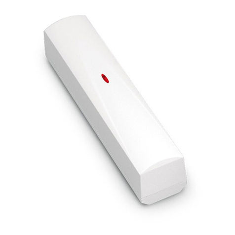
an independent source of power supply. Fig. 1. INT-CR device.
Control panel terminal
Wire color Function INTEGRA VERSA
brown power supply +EX / +EX1 / +EX2 KPD
white common ground COM COM
gray clock CK / CK1 / CK2 CLK
green data DT / DT1 / DT2 DTA
Table 1. Way of connecting wires to control panel terminals.
1.1 Setting the device address
Each device which is to be connected to the expander bus must have its own individual address.
Depending on the control panel type:
for INTEGRA: you can either set any unused address from 0 to 31 range;
for VERSA: you should set an address from 16 (10h) to 21 (15h) range.
To set the address, use the DIP-switch set on the device electronics board. A numerical value is
assigned to each DIP-switch. For OFF position, the value is always 0. The numerical values assigned
to individual DIP-switches in ON position are presented in Table 2. Using a screwdriver, set the
selected DIP-switches to ON position. Sum up the numerical values assigned to them to get the
address set in the device.
2 INT-CR SATEL
DIP-switch number 1 2 3 4 5
Numerical value
(for switch in ON position) 1 2 4 8 16
Table 2. Numerical values assigned to the DIP switches.
1.2 Identification
After completing the installation work and activating the alarm system, start the identification function
in the control panel (see the installer manual for the corresponding control panel). Only after
identification, the device will be properly supported. The device is identified as INT-IT.
2. Programming device parameters and options
Described below are the device parameters and options. They can be programmed using the D
LOAD
X
program or LCD keypad. Shown in square brackets are the names displayed in the LCD keypad of
INTEGRA system.
Name – individual name of the device (up to 16 characters).
Tamper alarms in partition [Tamper in part.] – the partition in which alarm will be signaled if the
keypad is disconnected from the control panel.
Master users / Users INTEGRA only – the master users (administrators) and users authorized to
use the device.
LED R [Partit. LED R] – way of partition reaction after removal of the card when the red LED is lit. The
partition can be fully armed or its status can remain unchanged.
LED G [Partit. LED G] / LED Y [Partit. LED Y] – way of partition reaction after removal of the card
when the green LED (mode A) or the yellow LED (mode B) is lit. The partition can be armed in one
of available armed modes, it can be disarmed VERSA only or its status can remain unchanged.
Alarm signaling [Alarm (time)] – the device can audibly signal alarms during the K
EYPAD
’
S ALARM
TIME
[VERSA] / G
LOBAL ALARM TIME
[INTEGRA].
Alarm signaling until canceled [Alarm (latch)] – the device can audibly signal the alarm memory.
Signaling entry delay [Entry time] – the device can audibly signal the entry delay countdown.
Signaling exit delay [Exit time] – the device can audibly signal the exit delay countdown, and in case
of the VERSA control panel also the auto-arming delay.
Auto-arm delay countdown [Auto-arm delay] INTEGRA only – the device can audibly signal the
auto-arming delay countdown.
Signaling card (hardware) [Hardw. signal] – the device can signal by a single beep that the card
code has been read out or the LED has lit up (the code is sent to the control panel after removal of
the card and only then the panel reaction to the read code is audibly signaled).
3 wrong cards alarm [Al. 3 unk .cards] – reading the unknown card code three times will trigger
alarm.
No auto-reset after 3 tampers [No autorst.3t.] INTEGRA only – you can disable the feature limiting
to three the number of tamper alarms from the expander.
Second code wait signaling [INT-IT-wt.2cd.] INTEGRA only – the device can signal by means of
LEDs that it is waiting for the second card. This is a global option (i.e. it is available in D
LOAD
X
program for each INT-CR device, but if enabled in any device, it will be enabled in all of them).
3. Use
Using the proximity card you can:
fully arm the partitions;
arm the partitions in mode A or B (the partition behavior in case of arming in mode A or B is
defined by the installer – see section P
ROGRAMMING DEVICE PARAMETERS AND OPTIONS
);
disarm the partitions;
clear alarm.

SATEL INT-CR 3
The installer will determine the partitions to be controlled by the device. The user can only control the
partitions which he is authorized to access.
Note: The INTEGRA control panel does not allow to toggle between the armed mode in partitions.
The partition must be disarmed first, and only then can be armed in another mode.
3.1 Full arming
1. Present the card to the device and hold up until the red LED comes on.
2. Remove the card from the device.
3.2 Arming the system in mode A
1. Present the card to the device and hold up until the green LED comes on.
2. Remove the card from the device.
3.3 Arming the system in mode B
1. Present the card to the device and hold up until the yellow LED comes on.
2. Remove the card from the device.
3.4 Disarming / alarm clearing
Present the card to the device and remove it after a while (approx. 0.5 second).
3.5 Audible signaling
If the S
IGNALING CARD
(
HARDWARE
) option is enabled, the device will generate a single short beep
after the card has been read and – if the card is held up – after each successive LED comes on.
After removal of the card, the device may generate the following sounds:
3 short beeps – confirmation of arming / disarming, alarm clearing.
3 long beeps – denial of arming / disarming, alarm clearing (the user does not have required rights,
or execution of the operation is impossible for other reasons, e.g. there no partitions which can be
disarmed or where alarm can be cleared).
2 short beeps [only when interacting with the INTEGRA control panel] – awaiting the second
card (the partition requires two codes for arming / disarming).
2 long beeps – unknown card.
The following audible signals can be generated in response to events in partitions served by the
device:
Continuous beep – alarm.
Long beeps separated by short pauses – alarm memory.
Long beep every second – fire alarm.
Short beep every 2 seconds – fire alarm memory.
2 short beeps every second – entry delay countdown.
Long beep every 3 seconds, followed by a series of short beeps for 10 seconds and 1 long
beep – countdown of exit delay (if the time is shorter than 10 seconds, only the final sequence of
short beeps will be generated).
A sequence of 7 beeps of diminishing duration, repeated every few seconds – countdown of
auto-arming delay.
3.6 Signaling by means of LEDs
Signaling when the proximity card is presented to the device:
Red LED lit – after removal of the card, the partitions specified by the installer will be fully armed.
Green LED lit – after removal of the card, the partitions will be armed in A mode (the installer defines
which partitions and in what mode will be armed).

4 INT-CR SATEL
Yellow LED lit – after removal of the card, the partitions will be armed in B mode (the installer defines
which partitions and in what mode will be armed).
Statuses indicated by LEDs (when the proximity card is not presented to the device):
All LEDs extinguished – none of the partitions controlled by the device is armed and there is no
alarm.
Red LED lit, the other LEDs extinguished – all the partitions which are to be armed after removal of
the card when the red LED is lit are fully armed.
Red and green LEDs lit – partitions controlled by the device are armed in A mode.
Red and yellow LEDs lit – partitions controlled by the device are armed in B mode.
Red LED lit, dimming momentarily, the other LEDs extinguished – at least one of the partitions
controlled by the device is armed.
Red LED lights up every 2 seconds, the other LEDs extinguished – alarm or alarm memory,
when none of the partitions is armed.
Red LED blinking slowly – alarm or alarm memory, when at least one of the partitions controlled by
the device is armed.
Red and yellow LEDs blinking alternately [only during interaction with INTEGRA] – awaiting the
second code enter.
Yellow, green and red LEDs blinking in turn – no communication with control panel.
4. Specifications
Supply voltage ..................................................................................................................12 V DC ±15%
Standby current consumption........................................................................................................ 65 mA
Maximum current consumption ..................................................................................................... 75 mA
Transmit frequency..................................................................................................................... 125 kHz
Supported card standards ............................................ UNIQUE, EM4001, EM4002, EM4003, EM4102
Environmental class according to EN50130-5........................................................................................II
Working temperature range.................................................................................................. -10...+55 °C
Maximum humidity........................................................................................................................ 93±3%
Housing dimensions .................................................................................................... 127 x 35 x 21 mm
Weight .............................................................................................................................................140 g
The declaration of conformity may be consulted at www.satel.eu/ce
SATEL sp. z o.o.
ul. Schuberta 79
80-172 Gdańsk
POLAND
tel. + 48 58 320 94 00
www.satel.pl
Other manuals for INT-CR
2
Table of contents
Other Satel Controllers manuals

Satel
Satel KNX-SA41 User manual

Satel
Satel Abax ACU-100 User manual

Satel
Satel MTX-300 User manual

Satel
Satel KNX-DIM21 User manual

Satel
Satel VERSA-MCU User manual

Satel
Satel MICRA VERSA-MCU User manual

Satel
Satel ABAX 2 ACU-220 User manual

Satel
Satel ABAX 2 ACU-280 User manual

Satel
Satel KNX-DIM21 User manual

Satel
Satel ASW-210 User manual

Satel
Satel KNX-BSA12L User manual

Satel
Satel RXH-1K User manual

Satel
Satel ACU-280 User manual

Satel
Satel ACU-220 User manual

Satel
Satel ACU-120 User manual

Satel
Satel KNX-BSA12H User manual

Satel
Satel RX-2K User manual

Satel
Satel MICRA VERSA-MCU User manual

Satel
Satel KNX-SA41 User manual

Satel
Satel ABAX 2 ACU-280 User manual