progeo JOKER JUNIOR 2.0 User manual

REHATEAM s.r.l.—vicolo Negrelli 5—31040 Castagnole di Paese TV - www.rehateamprogeo.com Service Manual JOKER JUNIOR 2.0 1
S E R V I C E M A N U A L
JOKER JUNIOR 2.0
Rev. 0 - 06/05/2020
SERVICE MANUAL
ENGLISH

REHATEAM s.r.l.—vicolo Negrelli 5—31040 Castagnole di Paese TV - www.rehateamprogeo.com Service Manual JOKER JUNIOR 2.0 2
SERVICE MANUAL
JOKER JUNIOR 2.0
GENERAL WARNINGS
ANY ADJUSTMENT CAN BE CARRIED OUT EXCLUSIVELY BY QUALIFIED
AND AUTHORIZED BY REHATEAM® PERSONNEL.
It is forbidden to carry out any modifications, even when possible, to the original
design.
Any adjustments and/or any modification that is carried out by non-authorized
personnel will immediately void the warranty on the product and it relieves
RehaTEAM® from any responsibility on any malfunctioning and/or damage due
to such adjustments/modifications.
Always contact RehaTEAM® and its technicians for any non-standard
requirements or modifications to allow them to evaluate such modifications and
verify that they will not compromise the normal and safe use of the wheelchair.
Any modification of the original parameters and set up could seriously
compromise the safe operation of the wheelchair causing damage to both the
user and the wheelchair itself.
After every adjustment made to the wheelchair, check carefully that all parts are
correctly fixed. Check that all screws and nuts are tightened and that all moving
parts are functioning correctly.
After any adjustment, always test the wheelchair before giving the product to
user and/or his/her attendant.
RehaTEAM® disclaims any responsibility for damage to the product or the peo-
ple due to any modification that is not properly performed or that, in any case,
does not guarantee safety to the user.

REHATEAM s.r.l.—vicolo Negrelli 5—31040 Castagnole di Paese TV - www.rehateamprogeo.com Service Manual JOKER JUNIOR 2.0 3
SERVICE MANUAL
Page adjustment
04 FRONT HEIGHT Caster on fork
05 FRONT HEIGHT Sliding system
06 FORK ANGLE
07 DIRECTIONALITY
09 REAR HEIGHT
10 SETTING (point of balance)
11 CAMBER AND CONVERGENCY
13 BRAKE
14 BRAKE SPACING
15 REMOVABLE SIDE GUARD
17 REMOVABLE ARMREST
19 FOOTPLATE
23 SEAT DEPTH
24 BACKREST HEIGHT
25 BACKREST ANGLE
26 QUICK RELEASE AXLE (rear wheel)
JOKER JUNIOR 2.0

REHATEAM s.r.l.—vicolo Negrelli 5—31040 Castagnole di Paese TV - www.rehateamprogeo.com Service Manual JOKER JUNIOR 2.0 4
FRONT HEIGHT
caster on fork
The entity of the adjustment obviously depends on the caster and fork’s sizes.
Screw off the bolt Vwhile holding the other.
Remove the axle P.
Position the caster to another hole, insert the axle and fix the bolt Vholding the one
on the other side.
Pay attention to the spacers between caster and fork.
SERVICE MANUAL
V
V
P
It is advisable to spread a
drop of mild lock thread
glue on the bolts V.
Fork
height
Holes intervals –12,7 mm
Sport –2 holes –h. 88
Piccola –3 holes–h. 112

REHATEAM s.r.l.—vicolo Negrelli 5—31040 Castagnole di Paese TV - www.rehateamprogeo.com Service Manual JOKER JUNIOR 2.0 5
FRONT HEIGHT
Sliding system
SERVICE MANUAL
B
A
C
Loosen the two bolts Aof the fork support B.
Slide the support upward or downward to the desired height.
Tighten the two bolts A.
Repeat the same operations on the other side making sure the height is the same.
The two front wheels must be touching the ground.
Make sure that, the all around rotation of the fork, the caster does not touch the frame.
The point of contact caster/frame determines the minimum front height you can reach
using the same caster.
If you need to further decrease the front height, you have to cut off the frame just as
necessary, for instance, along the line C. Then, slide the fork support and/or change
the position of the caster with respect to the fork.
Pay attention, though, to the footplate distance, see also adjustment sheet “footplate”.
Remember that the front height adjustment can affect the seat inclination, so it is
necessary to check and adjust the fork angle.
REHATEAM s.r.l.—vicolo Negrelli 5—31040 Castagnole di Paese TV - www.rehateamprogeo.com Service Manual JOKER JUNIOR 2.0 6
SERVICE MANUAL
It is advisable to pread a
drop of mild lock thread
glue on all grab screws G.
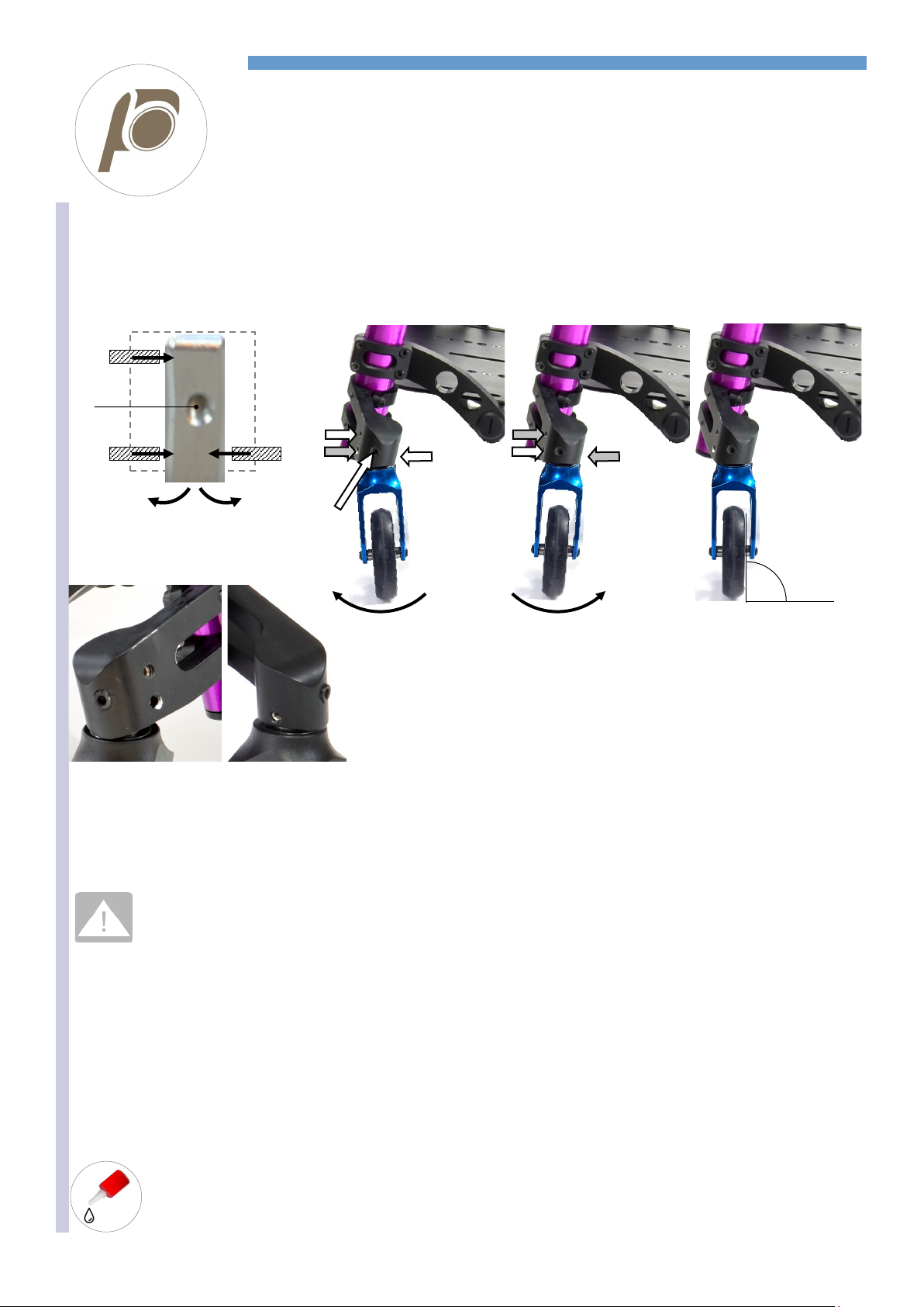
WORK ON A FLAT AND EVEN SURFACE
Whenever the seat height is changed or as periodic maintenance, check the fork angle and, if necessary, adjust it in order to have the fork
axis perpendicular to the ground.
The adjustment is possible by means of the four grab screws G1, G2 and G3 that make the axle Pturn on the fulcrum F.
P
To turn the fork
frontward
Loosen G2.
Screw G1 and G3
Perpendicularity
You can check the perpendicu-
larity with the help of a square
(or similar) vertically aligned to
the caster turned 90° with re-
spect to the driving direction of
the wheelchair
To turn the fork
backward
Loosen G1 and G3
Screw G2
To adjust the fork, once you know the direction (frontward or backward) towards which it is necessary to move the fork’s axle, proceed as
above-mentioned until reaching the correct angle.
You can also measure the perpendicularity by turning the fork by 360°: during the full turn, the wheel has to touch the surface in all posi-
tions.
If a headless bolt results hard to unscrew, DO NOT FORCE IT, but try to loosen the other two first.
If the fork’s axle (the axle P) results hard to move, slightly loosen the bolt of the fulcrum F(remember to screw it after adjust-
ment).
Once you reach the correct angle, screw all three headless bolts all the way down to the axle P, but without tightening.
In order to fix the system, tighten first one and then the other less than a quarter of a turn at once, the grab screws G1 and G2 (the front
ones) checking the perpendicularity; in fact, it may slightly change during this phase.
Should that happen, correct the angle proceeding in the same manner.
When you have tightened both headless bolts G1 and G2, you can tighten the headless bolt G3.
Check the perpendicularity again and, if necessary, correct it.
FORK ANGLE
G1
F
G2 G3
P
Rotation when
screwing
G1 and G3
Rotation when
screwing
G2 and G3
F
G1
G2 F
G3
90°
G1
F
G3
G2
G1
G3
G2
REHATEAM s.r.l.—vicolo Negrelli 5—31040 Castagnole di Paese TV - www.rehateamprogeo.com Service Manual JOKER JUNIOR 2.0 7
SERVICE MANUAL
DIRECTIONALITY
A very important aspect of any wheelchair is its directionality.
To check if the wheelchair goes straight, sit on it, push it and let it go until it stops.
If something is wrong, the slower the wheelchairs moves forward (momentum close to nothing), the more likely it turns right or left. There-
fore, if no or irrelevant turn occurs, the wheelchair is properly adjusted.
Cause Reason Solution
SURFACE The surface where the test is being performed is not even
and flat
Test the chair on even and flat surface
REAR WHEELS
The rear wheel are not equally inflated Inflate both tyres at the same pressure
The tyres of the two rear wheel are different or differently
worn out
Change the tyres
The rear wheels are not adjusted at the same height Adjust the rear wheel height
The camber of right and left wheels are different or differ-
ently adjusted
Adjust the camber.
The wheel, when turning, touches the side guard or the
brakes
Fix or replace the side guard. Add spacer on the
receiver. Adjust the brake.
The wheels doe not turn smoothly Clean or change the bearings
FRONT WHEELS The casters are not adjusted at the same height Adjust the front wheels at the same height
The tyres of the two front wheels are different or differently
worn out
Change the wheels
The fixing bolts of the fork/fork support/clamp are loosened Check and tighten all fixing bolts
The caster does not turn smoothly Clean the bearings.
Either or both forks are not adjusted so as their axis is per-
pendicular to the ground.
Adjust the fork axis inclination.
FOOTPLATE The footplate tubes are adjusted at different height. Adjust the tubes at the same height
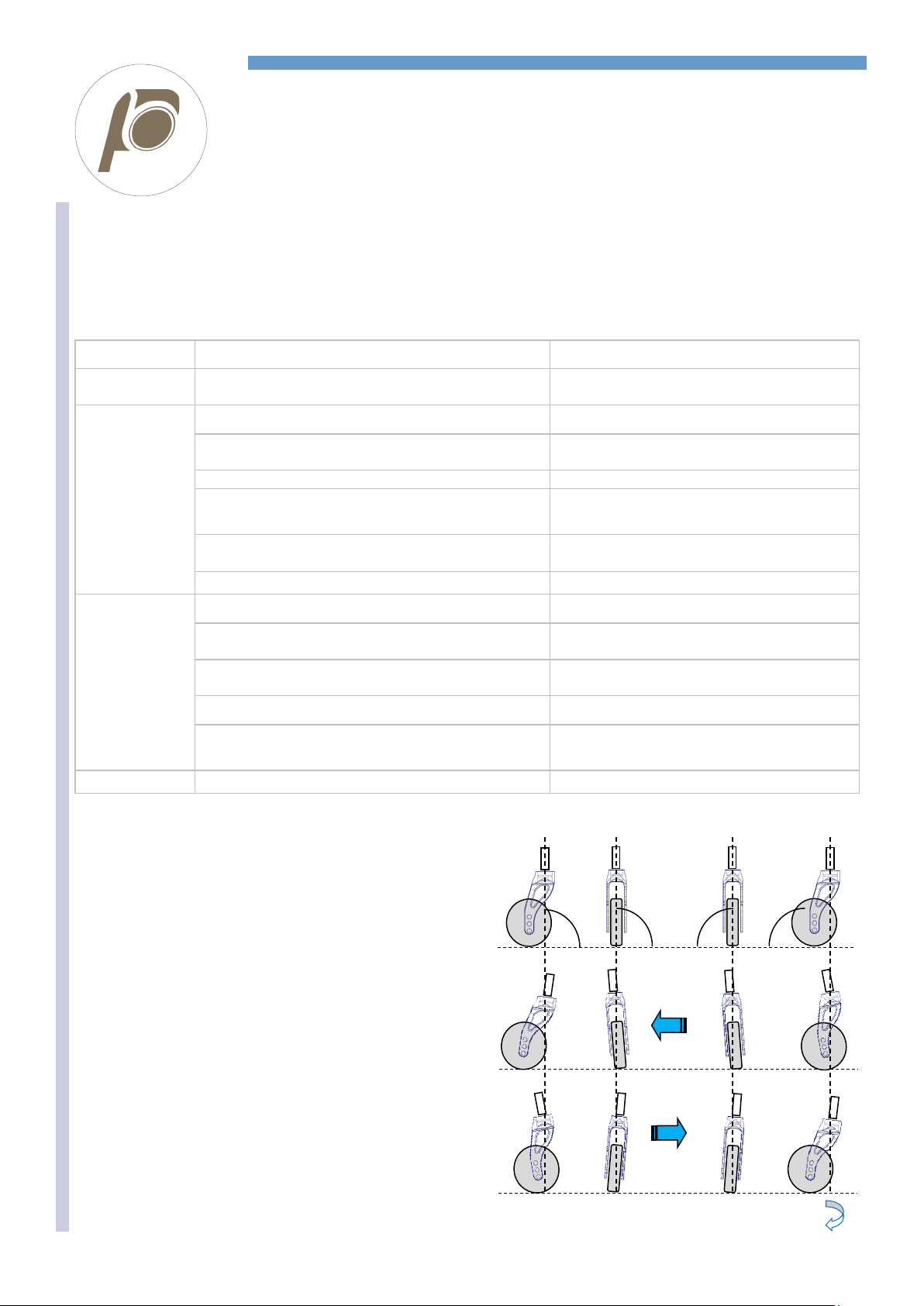
If the wheelchairs does not go straight, in most cases the reason
is the fork angle adjustment.
However, before working on the fork angle adjustment, check all
the points above mentioned.
First, make the test along a flat even surface to check the direc-
tionality.
1 The correct adjustment has both forks perpendicular to the
ground, that is, their axis at 90°.
2 If the wheelchair TURN RIGHT, the cause is one or more of
the following:
The RIGHT fork is tilted inwardly and/or backward
The LEFT fork is tilted outwardly and/or frontward
3If the wheelchair TURN LEFTT, the cause is one or more of
the following:
The LEFT fork is tilted inwardly and/or backward
The RIGHT fork is tilted outwardly and/or frontward
90° 90° 90° 90°
1
2
3
Follows next page
REHATEAM s.r.l.—vicolo Negrelli 5—31040 Castagnole di Paese TV - www.rehateamprogeo.com Service Manual JOKER JUNIOR 2.0 8
SERVICE MANUAL
DIRECTIONALITY
ADJUSTING THE DIRECTIONALITY
Check that the two forks are perpendicular to the ground. If they are not,
proceed with the adjustment of the fork angle following the instructions
on the sheet FORK ANGLE ADJUSTMENT.
If both forks axis are correct but the wheelchair still turns right or left, it
means that the latitudinal angle is not perfect.
This may be due to hit, to improper pressure exercised on the fork or its
support, or to a tiny imperfection among all parts fixed together due to
their manufacturing tolerances.
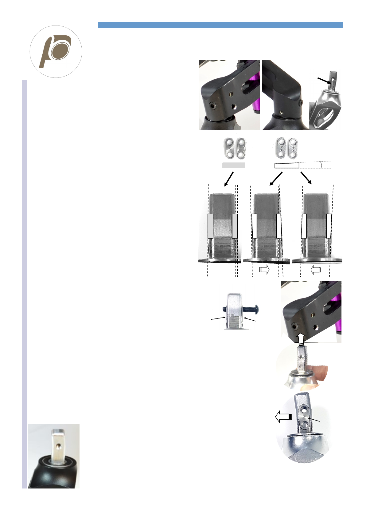
You can fix the fork axle P in three different angles to correct the direc-
tionality.
Loosen all four grab screws G, remove the bolt Fand slide off the fork
complete with the axle P.
The axle has two side hollows Bwhere you have to cast the flat inserts
C0 or the 1° titled inserts C1 that are recognizable thanks to two dots.
With the flat inserts C0, the axle keep its original inclination.
With the tilted inserts C1, the axle tilts by 1° right or left according to
how to cast them in the hollows—see images.
Note: you can cast the inserts only as indicated in these images.
Once you have casted the inserts C0 or C2, it is advisable to try to
screw the bolt Fto check there is no difficulty. Sometimes, in fact, the
holes of the inserts may have working burr that make the bolt hard to go
through.
To mount the fork unit. Insert the axle Pin the fork support paying atten-
tion to the orientation of the same axle. In fact, the axle is not straight,
but it shows a bend. Such bend must be facing to the rear of the wheel-
chair.
Insert and screw the bolt Fwithout tightening it much (it is enough to screw it up to stop).
Adjust the fork angle —see sheet “fork angle”.
Note. This type of adjustment can take place even at original assembly, therefore, you may find the in-
serts C0 on one axle and C1 on the other, for instance.
The wheelchair is not supplied with supplementary inserts, therefore, it will be necessary to order them
when needed.
Axles without inserts
Until 2019 the axles had no inserts C0 or C1. There were 0°, 1°rh and 1°lh axles.
To adjust the directionality, it is necessary to change the axle.
B
P
0° XY1°
Y X X Y
X Y Y X
0° 1° 1°
P P P
C0 C1
SIDE VIEW
P
FRONT REAR
C0 oC1
P
C0
or
C1
C0
or
C1
F
G1
G2 F
G3
REHATEAM s.r.l.—vicolo Negrelli 5—31040 Castagnole di Paese TV - www.rehateamprogeo.com Service Manual JOKER JUNIOR 2.0 9
SERVICE MANUAL
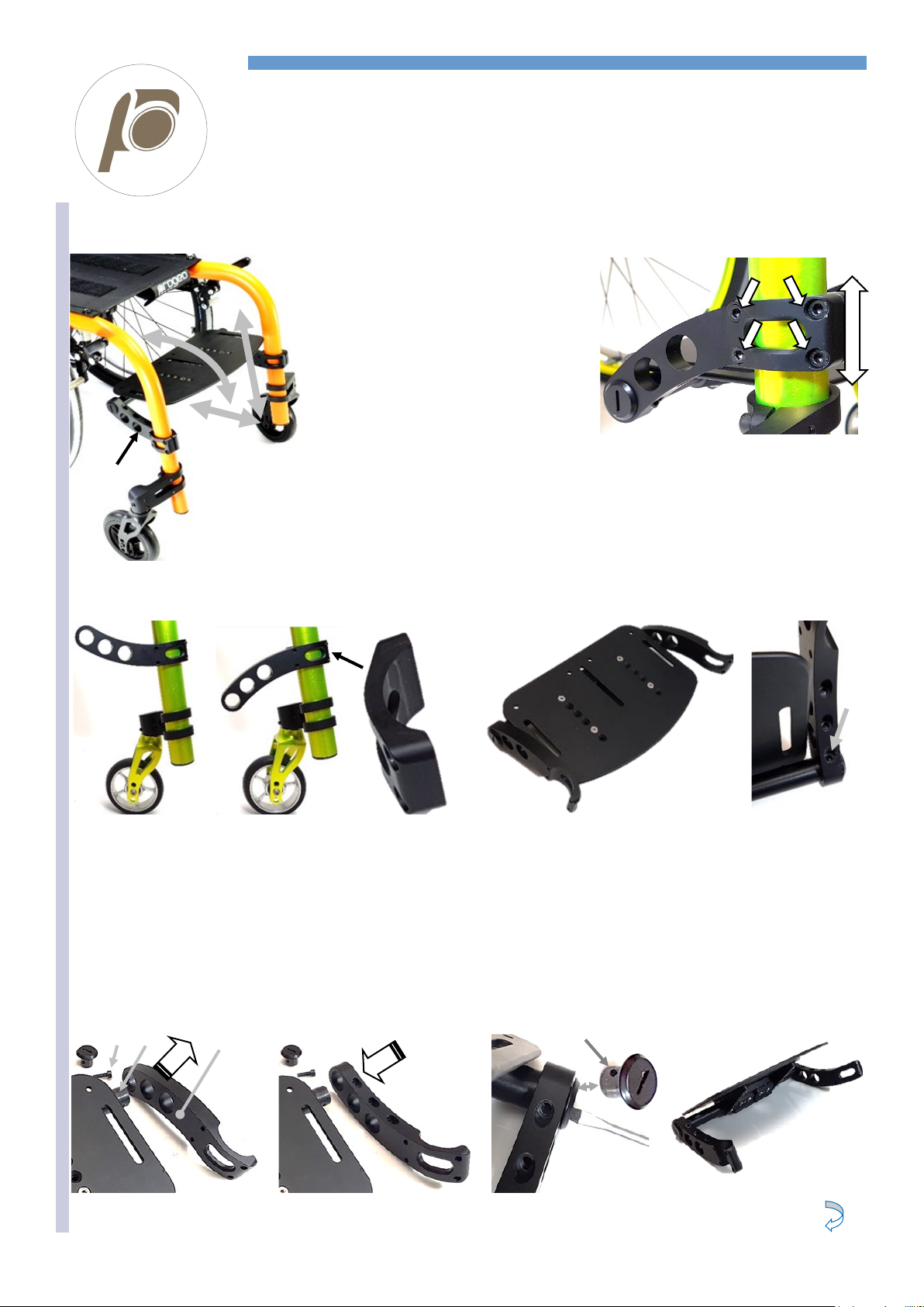
REAR HEIGHT
STANDARD REAR UNIT
When decreasing the rear height it is necessary to remove the mudguard or the armrest first, fact,
the tyre will touch it and it will impede the adjustment.
If the side guard is straight, leave it where it is.
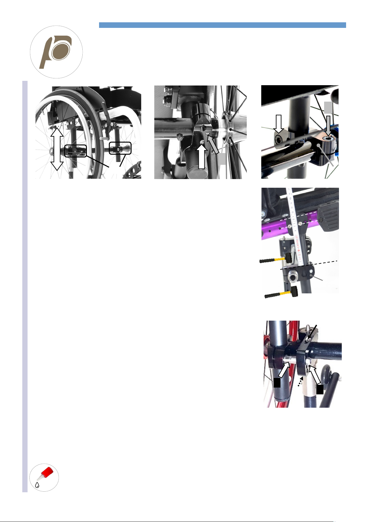
Loosen the grab screw Bon the rear lower side of both clamps A.
Loosen the bolt Cof both clamps A.
Now you can slide the two clamps Aalong the posts E.
Should the clamps be hard to slide, loosen the bolts B and C and/or, with care, hit them with a
mallet to the necessary direction. Such operation may result particularly useful for the final adjust-
ment when the necessary movement is very little.
The rear axle D always remains fixed to the clamps A.
The grab screw Xand the bolt Yare not involved is this adjustment.
Slide the system to the necessary height.
Fix the clamp Aof either side, tightening the bolt Chard and then tighten the grab screw B.
Before fixing the other side, check the height is the same.
To make sure that right and left side are at the same height, take measure from two “fix points”, for
instance: the straight line from the upper side 1of the clamp Ato the line 2of the holes of post’s
plate that fixes the frame or to the line 3of the upper side of the same plate.
When changing the rear height it is necessary to modify the mudguard. However, if the side-guard is
straight you may leave it as it is, its upper edge will be lower or higher with respect to the tyre.
To remove and adapt the side guards, follow instruction of sheet “side guard adjustment”.
In presence of anti-tipper support, the bolt Cis different; in fact, it is involved in the support’s assem-
bly. To proceed with the height adjustment, remove the nut G, loosen the two bolts Hand move the
support away from the bolt C.
Now you can loosen the bolt Cand continue the adjustment as above explained.
To re-assemble the support, slide it in along the bolt Cchoosing the one of the 4 holes and check which one give you the best inclination
of the anti-tipper. Then fix it with the nut Gand finally tighten the two bolts H.
Remember that the rear height adjustment can affect the seat inclination, thus, it is necessary to check and adjust the fork angle.
It is advisable to spread a drop
of mild lock thread glue on the
on the grab screws B.
C G
H
H
B X
E
C Y
A
D
A
3
2
1
A

REHATEAM s.r.l.—vicolo Negrelli 5—31040 Castagnole di Paese TV - www.rehateamprogeo.com Service Manual JOKER JUNIOR 2.0 10
SERVICE MANUAL
SETTING (point of balance)
A
S
B
D D
1 2 3 4
C C
12.5 12.5 12.5
REF.
25 25
X
1 2 3 4
Y
1
E
1 3
PRUDENTIAL, S = 60 mm approx.
Plate fixed through holes 1and 3leaving in
sight two frame holes between the plate and
the nut Ethat fix the backrest support.
2
E
2 4
STANDARD, S = 72.5 mm approx.
Plate fixed through holes 2and 4leaving in
sight two frame holes between the plate and
the nut Ethat fix the backrest support.
3
E
1 3
ACTIVE, S = 85 mm approx.
Plate fixed through holes 1and 3leaving in
sight three frame holes between the plate
and the nut Ethat fix the backrest support.
You can adjust the setting Sby moving the posts A(to which the rear axle is fixed) along the
frame. The frame has pre-drilled holes every 25 mm.
The post fixing plate Bhas 4 holes, 12.5 mm from one another. Such holes allows for inter-
mediate adjustment.
To change setting, remove both nuts/washers Dthat fix the bolt C. screw off the bolts i C(the
holes of the plate Bare threaded).
Repeat the same operation on both sides of the wheelchair.
WARNING: if you remove only one nut and then try to unscrew the corresponding bolt, this
bolt may result particularly hard to unscrew because the second one, still tightened with the
nut, can create a pressure on the first.
If you wish to make the setting 12.5 mm MORE ACTIVE, starting from the position as shown
in the picture RIF. (bolts Cfixed through holes 2and 4), move the post Aforward along the
frame until aligning the hole 1 with the closest hole of the frame, in this case X.
The hole 3will consquently be aligned.
If you move the post forward by another 12.5 mm, the hole 2will align to the frame hole X.
The hole 4will consquently be aligned.
If you wish to make the setting 12.5 mm MORE PRUDENTIAL, starting again from the posi-
tion as shown in the picture RIF. (bolts Cfixed through holes 2and 4), move the post Aback-
ward along the frame until aligning the hole 3 to the frame hole where the hole 4was aligned.
The hole 4will consequently be aligned.
If you move the post backward by another 12.5 mm, the hole 4will align to the frame hole Y.
The hole 2will consequently be aligned.
Once you have determined the new setting, screw the bolts Con the plate Ball the way
down. Then, insert washers and nuts Dand fix them while holding the corresponding bolts.
While you tighten the nut D, hold the bolt Cotherwise the bolt will loosen.
Following the instructions above, you can obtain other more active or prudential settings.
The pictures 1, 2 and 3 show the combinations to get the three pre-determined settings.
Check and adjust the for angle.
Adjust the brakes.
Modify the mudguards.
REHATEAM s.r.l.—vicolo Negrelli 5—31040 Castagnole di Paese TV - www.rehateamprogeo.com Service Manual JOKER JUNIOR 2.0 11
SERVICE MANUAL
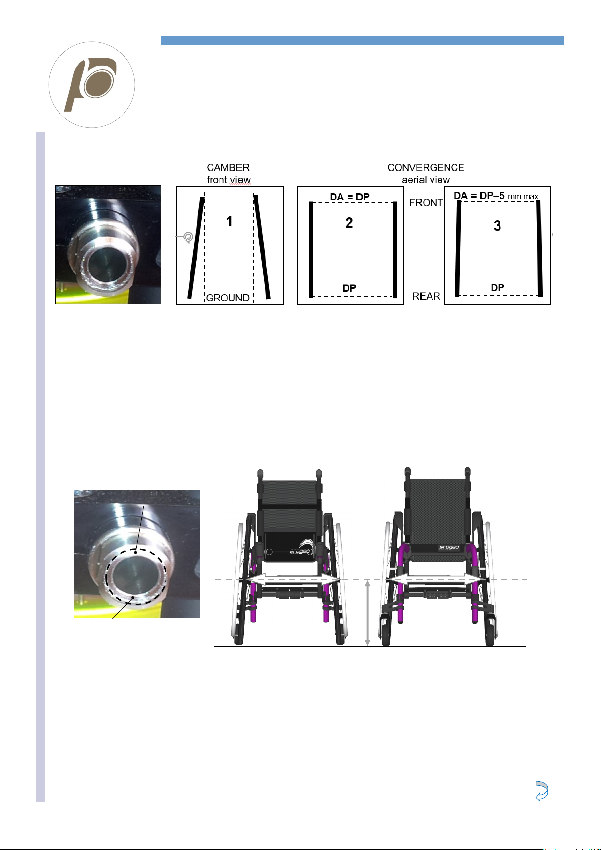
CAMBER AND CONVERGENCY
The hole of the cambered receiver, since it is inclined, is not centered.
Therefore, check the wheel receiver its narrow edge looking upward and its wider edge down. If opposite, the convergence is oppo-
site, too (the wheels are opening apart at top!).
At 27.5 cm from the floor with 22” wheel or 30 cm with 24” wheels, take the measure centre-to-centre between the two tyres in front
and at rear.
If the two measures are equal or the front one is slightly narrower (max. 5 mm), you have a good convergence as drawing 2 or 3.
If different, you have to adjust the convergence.
Follows next page
WORK ON A FLAT AND EVEN SURFACE
The wheel receiver gives the rear wheel camber (cambered receiver).
The two wheel receivers are fixed to the rear axle, thus, to adjust the convergence, it is necessary to turn the axle.
The drawing 1shows same inclination (camber) of both rear wheels.
With cambered wheels, it is necessary to check/adjust the convergence, the distance between the two wheels in front and at rear.
The drawing 2 shows the aerial view of the wheels and the front distance DA is equal to the rear distance DP, while the drawing 3,
DA is narrower than DP by maximum 5 mm.
We can say that a good convergence has the front distance DA equal to or slightly narrower than the rear distance DP.
DA must not be wider than DP. In such case, the fluency of wheelchair will not be good.
RECEIVER
Narrow side up
Wide side down
27.5 cm
FRONT REAR
DA DP
REHATEAM s.r.l.—vicolo Negrelli 5—31040 Castagnole di Paese TV - www.rehateamprogeo.com Service Manual JOKER JUNIOR 2.0 12
SERVICE MANUAL
CAMBER AND CONVERGENCY
Take the measures again and if necessary, repeat the same operation until you reach the correct convergence, se previous page.
If the clamp moved when you loosened the fixing bolts, position the axle’s end (not the receiver) at 8 mm from the clamp for the standard
rear unit, or 5 mm if Full Carbon plate and fix one side, first.
Tighten the bolt Aand then the grab screw B.
Before fixing the other side, check the front wheels (considered already adjusted at the same height) are both touching the ground. If one do
not touch, turn the frame on axle on its loosened side to the necessary extent.
If the quick release axle of the rear wheel hardly or do not pass through the receiver, loosen A, B and remove it. Then, tighten all parts
again, but first pass the hole with a ½” reamer to remove any possible tiny deformation (see also adjustment sheet “quick release axle”).
It may be a little harder to position and fix the other side due to the pressure given by the seat canvas, but you have to respect the same
distance.
Check the measure from a fix point of the frame to the centre of the tyre on each side. Should there be a
difference greater than 2-3 mm, check the distance between clamp and axle as above mentioned.
If necessary, correct the adjustment.
8 mm
D
D
Loosen the bolt Aand then the grab screw B. The grab screw Cis not involved in this adjustment.
Loosen the above mentioned screws just enough to let you turn the rear axle with your hand but without the clamp sliding along the axle. If
that occurs, you can continue with the adjustment. You will fix that later.
Turn the rear axle (clockwise or anticlockwise) and observe how and to what extent the wheels move.
A good reference is the bolt D, in fact its axis, should be perpendicular to the ground, except for the 4° receiver fixed in the centre position
(2) which is rotated by 90° with respect to the other two positions (1 and 3); in such case, the bolt Dshould be parallel to the ground.
2
1 3
Boccola 2°
Boccola 4°
A
B
C
REHATEAM s.r.l.—vicolo Negrelli 5—31040 Castagnole di Paese TV - www.rehateamprogeo.com Service Manual JOKER JUNIOR 2.0 13
SERVICE MANUAL
BRAKE
WHEN ADJUSTING THE BRAKES, THE TURES MUST BE INFLATED TO THE CORRECT PRESSURE (except solid tyre)
The position of the brake depends on the position of the rear wheel.
B
A
D
B
CX
B
E
G I
H
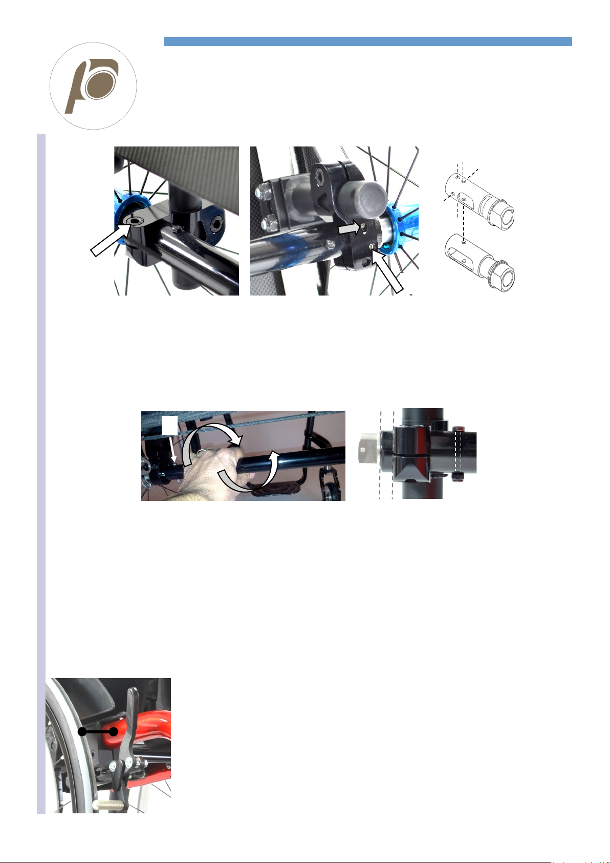
Loosen the bolt A that you find on the lower side of the support B.
Position the brake-knurled rod Pat a distance Dof a few millimetres and
parallel to the ground.
Temporarily tighten the bolt Aand try the brake out to check if the ad-
justment is good.
If necessary, repeat the same operation to reach the good adjustment.
A good adjustment has the brake not too hard to engage but braking, so
you will have to find the suitable compromise.
Once reached the correct position, tighten the bolt A.
Proceed in the same way for the other side.
In some cases, it may be necessary to move the support Bto reach the
correct adjustment.
To move the support B, loosen the grab screw bolt Gthat you find on
the inner side of the support.
Then, loosen the bolt Ethat you find on the outer side of the support.
This bolt screws into the front axle X. Now, move both supports with the
axle frontward or backward until necessary.
Make sure the two supports are at the same distance along the frame.
Tighten the bolt Bfirst and then the grab screw Gon both supports.
The grab screw Cbecomes useless if it is in line with a hole on the
frame. Yo uwill realize that because, when you screw it, it will not touch
the frame and it will not make any pressure. In that case, loosen the
grab screw, loosen the bolt Eand move the support a few millimetres.
Finally tighten the bolt and the grab screw.
In other cases, the blade Gof the removable sideguard or armrest may
interfere with the brake rod Iimpeding the brake adjustment. Should
that happen, you can either move the sideguard/armrest support Hto a
different position –see also adjustment sheet “removable sideguard” or
“removable armrest” - or cut off a part of the brake rod.
Grab screw Gin line with a hole of the frame –move the support

REHATEAM s.r.l.—vicolo Negrelli 5—31040 Castagnole di Paese TV - www.rehateamprogeo.com Service Manual JOKER JUNIOR 2.0 14
SERVICE MANUAL
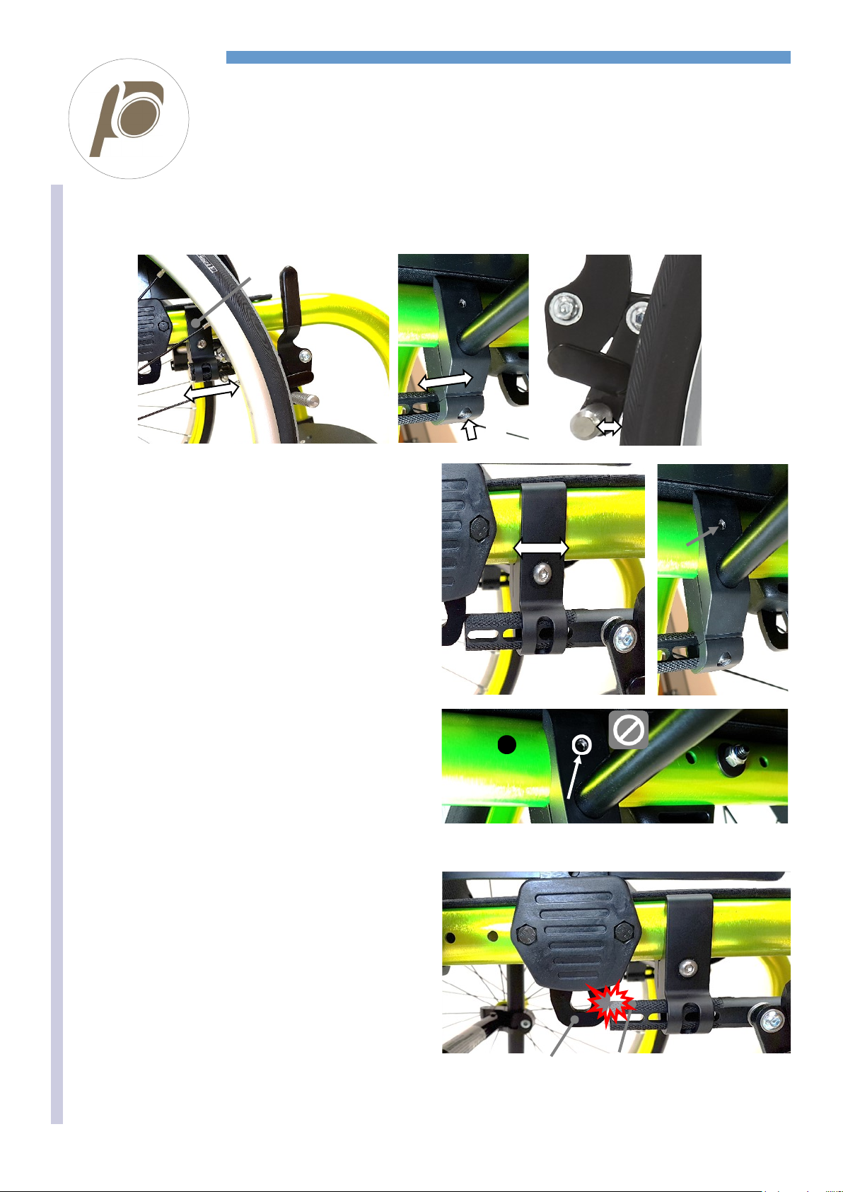
BRAKE SPACING
B
Spread
some strong
thread lock
glue on the
bolt B.
In several cases, the distance between the tyre and the frame can be such
as to make need moving the knurled rod Pmore external.
When originally assembling the wheelchair, such possible modification is
already taken into account.
In case of a post-sale modification that results in the rear wheels being
more external (from 0° to 2° or 4° camber; seat width enlargement; a dif-
ferent wheel), the brake may not work efficiently anymore, therefore, you
will have to move the knurled rod. The brake is efficient if the knurled rod P
is at least 5 mm beyond the tyre’s mid-line.
In all cases, check the brake efficiency.
Remove the bolt B. In order to remove it, put the knurled rod in a vice and heat it with a hot air blower because the bolt is locked with strong
lock thread glue. DO NOT FORCE WHEN UNSCREWING IT, you may damage the bolt’s head irremediably.
Once you have removed the bolt, the knurled rod comes off, too. Replace the bolt Baccording to the spacer C(7 or 11 mm) you will add.
Put some strong lock thread glue on the bolt Band assemble the spacer Cand the knurled rod A.
Put the knurled rod in a vice and tighten the bolt B hard.
It is also possible to move the brake structure Efrom the adjustment rod F.
Remove the two nuts Gand then the two bolts B.
Remove the spacers Haround which the spring is assembles.
Observe how the spring is assembled because you will have to assemble it back later in
the same way (you can always have a look at the other brake that is symmetric).
Insert the spacers H(H1= original; H2= 7 mm longer).
Position the spring and assemble the structure to the adjustment rod.
Start screwing the two bolts Ball the way down and then the two nuts G.
Should the brake movement be hard, slightly loosen the bolts B.
E F
G
B

REHATEAM s.r.l.—vicolo Negrelli 5—31040 Castagnole di Paese TV - www.rehateamprogeo.com Service Manual JOKER JUNIOR 2.0 15
SERVICE MANUAL
REMOVABLE SIDE GUARD
At each adjustment, spread some mild Follows next page
A
B
A C
A
D
B
1 G B
F
E
2
B
F
Ø8
You will notice that the holes for the support fixing are 8 mm wide, whereas, the others are 6 mm wide.
Position the support without the spacers Gmore frontward or backward and temporarily fix it with one bolt Fplus washer and nut E. Check
the position of the side guard. If it is not satisfactory, try another position of the support following the same method.
Once you reach the best position, remove the support B.
Enlarge the support fixing holes to 8 mm. Insert the spacers Gin the support B.
Mount the support Bon the frame, insert the bolts Fand fix it all with washers and nuts E.
In picture 2, compared to picture 1, the support has been moved backward by one position.
WARNING: do not fix the support Bwithout the spacers G: the system will results less stable.
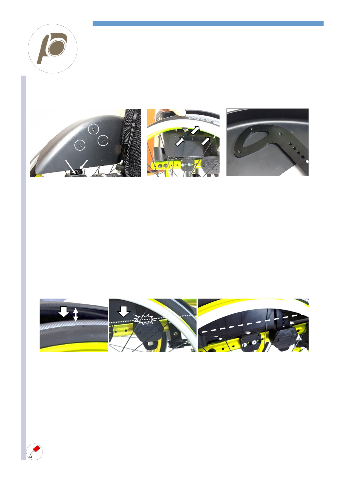
After every adjustment of the rear wheel, you have to adjust the position of the side guard. You have to adjust the side guard at approxi-
mately 5 mm from the tyre.
The side guard is fixed to three points on the blade Athat slides in the support Bfixed to the frame.
HEIGHT ADJUSTMENT
The blade Ashows, in its vertical side, a series of holes to fix the bolt Cthat inserts in the hollow Dof the support B. Therefore, to change
the height, just remove the bolt Cand screw it in another hole.
Warning: do not tighten the bolt C excessively: it may damage the threaded hole until making it unusable.
HORIZONTAL ADJUSTMENT
You can fix the support Bin different positions along the frame.
Screw off the two nuts and washers E.
Remove the support Bwith its bolts Fby pulling it off. The spacers Gmay remain stuck to the support or to the frame.
Should they remain stuck to the frame, it is necessary to remove them. If such operation results difficult, you can help yourself with a flat-
head pin and a hammer.
REHATEAM s.r.l.—vicolo Negrelli 5—31040 Castagnole di Paese TV - www.rehateamprogeo.com Service Manual JOKER JUNIOR 2.0 16
SERVICE MANUAL
REMOVABLE SIDE GUARD
SIDE GUARD MODIFICATION
If one, the other or the combination of both adjustment above mentioned are not satisfactory, you can modi-
fy the side guard. Every side guard is shaped to measure according to the configuration of the wheelchair
when originally assembled. The shape of the side guard always allow for a reasonable good range of adap-
tation. Note: if the side guard is straight, you can decide to modify it or not.
A When you decrease the rear height, you have to move the side guard up.
At each adjustment, spread some mild
lock thread glue on the bolts Cand H.
H
D C
3
2
1
3
1 2
1. Remove the three bolts Hto take the side guard off the blade.
2. Position the side guard at approximately 5 mm from the tyre, always leant on the blade A. The bolt Con the blade must be inserted in the
hollow Dof the support.
3. While holding this position, mark the point where it is necessary to drill the first new hole (1 or 2; 3 is usually not accessible with the rear
wheel on).
4. To do so, use a point and let it through the accessible hole. If the rear height adjustment is remarkable, you may need a new sideguard.
5. Drill a 5 mm on the sideguard where you have marked it.
6. Countersink the hole.
7. Insert and screw the bolt H.
8. To drill the second hole on the side guard, follow instruction from 3 to 7.
9. To drill the third hole, remove the side guard, mark the point where to drill and follow instruction from 5 to 7.
Advice for drilling. While drilling a hole, such hole may result slightly moved with respect to the precise point you marked. For the first hole,
that move does not cause any trouble. On the other hand, for the second and third hole, it may cause a non-alignment between hole on the
side guard and hole on the blade. A good method to be more precise, once you reach point 5, is to use a 4 mm drill pin (in order to avoid
damaging the thread of the hole on the blade) and drill the side guard. Then, use and let a M5 tap through the threaded hole of the blade
and out of the side guard.
BWhen you increase the rear height, you have to move the side guard down.
X
B
If the lower side of the side guard is in contact with the support, it is necessary to cut it.
Measure the distance Xfrom side guard and tyre and subtract 5 mm (es: 18-5 = 13 mm to cut).
Remove the three bolts Hto take the side guard off the blade.
Draw the cut line according to the result you got.
Saw the side guard along the drawn line and round off the edges with a scissors blade or thin sand paper.
Continue with instruction A.
C When you change the setting, you have to move the side guard frontward or backward according to the new position of the rear
wheel, but the height of the side guard remains the same.
Proceed with instruction A.
D When you change both the rear height and the setting, you have to move the side guard up or down and forward or backward.
Continue with instruction A and, if necessary, instruction B, too

REHATEAM s.r.l.—vicolo Negrelli 5—31040 Castagnole di Paese TV - www.rehateamprogeo.com Service Manual JOKER JUNIOR 2.0 17
SERVICE MANUAL
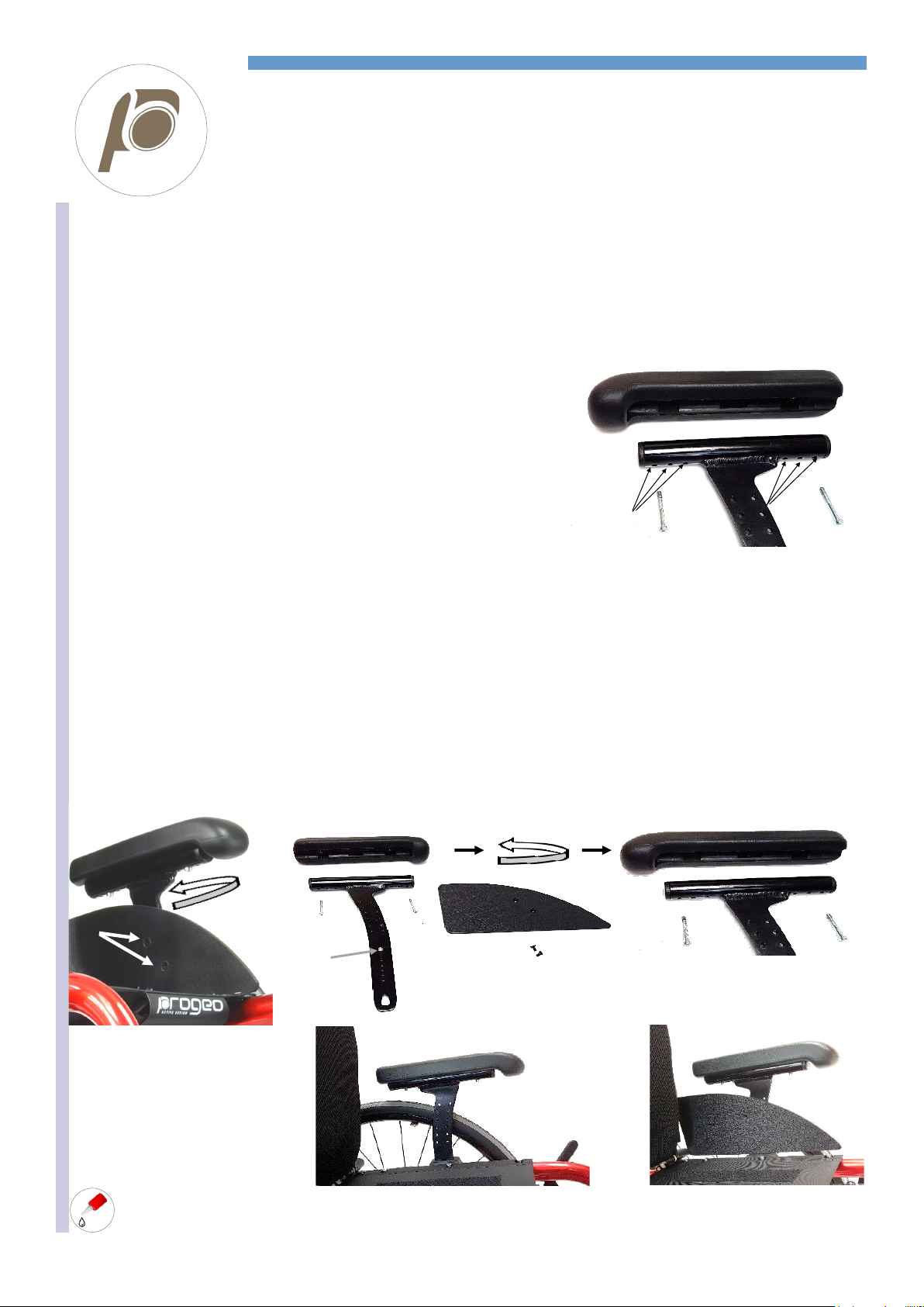
REMOVABLE ARMREST
At each adjustment, spread some mild
lock thread glue on the bolts Cand H.
B
A
C
A
B
V
You can adjust this armrest in height and depth
HEIGHT ADJUSTMENT
The blade Ahas, in its vertical part, a series of holes where to screw the bolt C. This bolt engages into the hollow Dof the support B. There-
fore, to change the height, just remove the bolt Cand screw it in another hole.
If you need to lower the armrest, the side guard could touch the support Band thus impede the adjustment. In such case, it is necessary to
cut the lower side of the side guard. Remove the two bolts Vand draw a line where to cut the side guard where necessary or just above.
Saw the side guard along the line and round off the edge with a scissor's blade or with fine sand paper. Assemble the side guard.
WARNING: do not tighten the bolt C and V excessively: it may damage the threaded hole until making it unusable.
HORIZONTAL ADJUSTMENT
Follow the instructions of the adjustment sheet “removable side guard”.
SIDE GUARD MODIFICATION: should you want or need to change position of the side guard,
remove the two bolts V.
1. to move it frontward or backward, position it where you wish and, using one of the holes on
the blade, mark the point where to drill the first hole. If one of the two existing holes on the
side guard is usable, skip point 2 and 3.
2. Drill a 5 mm hole where you have marked.
3. Countersink it.
4. Insert and screw the bolt V.
5. Check the position of the side guard and mark the point where to drill the second hole.
6. Remove the side guard.
7. Drill the hole and then countersink it.
8. Assemble the side guard with the two bolts V.
9. If you need to move the side guard up or down, follow the same instructions, or, in some
cases, you may use the same holes of the side guard and fix it to other holes on the blade.
V
Follows next page
REHATEAM s.r.l.—vicolo Negrelli 5—31040 Castagnole di Paese TV - www.rehateamprogeo.com Service Manual JOKER JUNIOR 2.0 18
SERVICE MANUAL
REMOVABLE ARMREST
At each adjustment, spread some mild
lock thread glue on the bolts Hand V.
V H A H
C V
Advice for drilling. While drilling a hole, such hole may result slightly moved with respect to the precise point you marked. For the first hole,
that move does not cause any trouble. On the other hand, for the second and third hole, it may cause a non-alignment between hole on the
side guard and hole on the blade. A good method to be more precise, once you reach point 5, is to use a 4 mm drill pin (in order to avoid
damaging the thread of the hole on the blade) and drill the side guard. Then, use and let a M5 tap through the threaded hole of the blade
and out of the side guard.
PAD POSITIONING: you can fix the pad Iof the armrest in three different positions
with respect to the tube of the blade. Such tube has, in fact, three pairs of holes.
Just remove the two bolts H, move the pad to either one of the other two position and
fix it again with the two bolts.
BLADE ORIENTATION: you can assemble the armrest with blade Afacing frontward or backward.
the difference between the two positions is approx. 3 cm.
To change the orientation of the blade, remove the armrest.
Screw off the two bolts Vand remove the side guard.
Screw off the two bolts Hand remove the pad I.
Reverse the pad and fix it to the tube with the two bolts.
Insert the armrest into the opposite support; right side become left.
No need to work on the bolt C.
Position the side guard and, through one of its two existing holes fix it to the blade Awith one bolt (the second hole is hardly useable).
Mark and then drill the second hole on the side guard following the same instructions for the side guard modification.
Repeat the same operation for the other armrest.
H H
I
REHATEAM s.r.l.—vicolo Negrelli 5—31040 Castagnole di Paese TV - www.rehateamprogeo.com Service Manual JOKER JUNIOR 2.0 19
SERVICE MANUAL
FOOTPLATE
You can adjust this type of footplate in height, angle and depth.
HEIGHT ADJUSTMENT
1) Sliding the system
Loosen the four bolts Bof both supports A.
Slide the footplate upward or downward to the
necessary height.
Fix one of the two supports Atightening the four
bolts Bevenly.
Check the two supports are at the same height
and tighten the second support.
2) supports orientation
You can orientate the supports Afacing upward or downward.
Therefore, reversing their orientation, you can reach other footplate distances.
To reverse the orientation, you need to detach the whole footplate unit from the frame.
To do so, remove the four bolts Bof both supports Aand detach the fixing plate C.
Now, remove the footplate unit.
(In this case, we start with the footplate with the supports facing downward).
A
B
A
Screw off the bolt Dand pull off the support Afrom the tube E. The cap Fcomes off, too.
If the support is hard to come off, you can gently use a mallet.
Repeat the same operation for the other side.
Now, reverse the assembly of the supports. You will notice their changed orientation.
To mount the footplate unit, insert the support Aon the tube E. then, insert the cap Finto the tube E.
Now, align the support’s hole to the threaded hole of the cap. To align the holes, you can help yourself with a screw driver.
Carefully insert the bolt Dand tighten it.
Repeat the same operation for the other side.
Footplate with supports
facing downward.
C
A
A
D
E
A
Follows next page
F Footplate with supports
facing upward.
F D E A Threaded hole
REHATEAM s.r.l.—vicolo Negrelli 5—31040 Castagnole di Paese TV - www.rehateamprogeo.com Service Manual JOKER JUNIOR 2.0 20
SERVICE MANUAL
FOOTPLATE
Follows next page
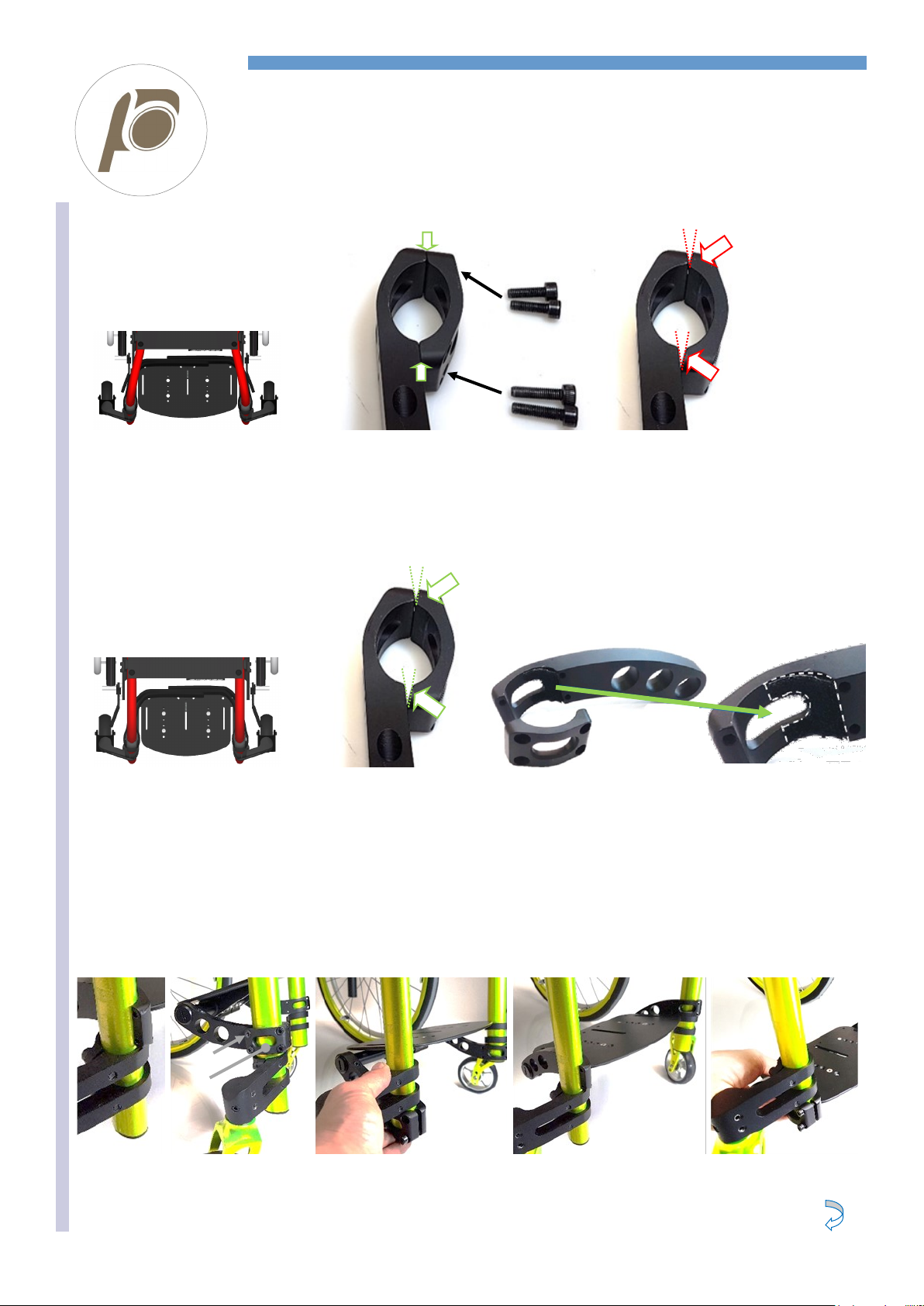
ASSEMBLY OF THE FOOTPLATE UNIT
Once you have assembled the footplate unit with the supports, you can assemble the complete unit to the frame.
Position the complete unit on the frame, either above or below the fork supports.
It results easier, initially, to tilt the unit on one side because you will need to widen the two frames apart a little bit.
Fix the supports with the plates Cand their bolts B.
Pay particular attention when fitting the bolts in order to prevent damaging the threaded holes of the support A.
Now you can adjust the footplate distance following the instruction “HEIGHT ADJUSTMENT, 1) sliding the system” on the previous page.
Montaggio con supporti orientati verso l’alto. Montaggio con supporti orientati verso il basso.
B
C
ASSEMBLY WITH ABDUCTED FRAME
The two faces of the plate Amust match
those of the support A.
The wrong assembly has “V-shape open-
ings”, see arrows.
ASSEMBLY WITH PARALLEL FRAMES
You have to mount the plate Copposite,
thus, you will see the “V-shape openings”.
Over the inner rear side of the support A
there must always be present a compensa-
tion shaped adhesive Velcro (or similar).
A
5 X 16
5 X 20
OK NO
AC
Table of contents
Other progeo Wheelchair manuals

progeo
progeo JOKER ENERGY User manual

progeo
progeo ego User manual

progeo
progeo JOKER EVOLUTION User manual

progeo
progeo Raptor User manual

progeo
progeo ego User manual

progeo
progeo JOKER ENERGY User manual

progeo
progeo EXELLE VARIO Classic User manual

progeo
progeo JOKER R2 User manual

progeo
progeo Junior User manual

progeo
progeo VARIO CARBON User manual

progeo
progeo Joker User manual

progeo
progeo Tekna Tilt User manual

progeo
progeo DUKE User manual

progeo
progeo EGO Series User manual

progeo
progeo MOTOTRONIK User manual

progeo
progeo Physio Air User manual

progeo
progeo EASY TILT User manual

progeo
progeo YOGA User manual

progeo
progeo YOGA User manual

progeo
progeo Exelle Junior User manual


