progeo Exelle Junior User manual

Service manual
FRAME LENGTH AND SEAT DEPTH ADJUSTMENT XJ
Necessary tools: 5 mm Allen key, 10 mm spanner, mallet, (5 and 8 mm drill pin)
The frame of the model Exelle Junior has three different lengths that are
considered “ideal” according to the seat depth PS (1,2,3,4,5).
Thus: SHORT for PS 27.5-30 cm;
MEDIUM for PS 32.5-35 cm;
LONG for PS 37.5-40 cm.
“Ideal” does not mean “compulsory”, therefore, you can choose when
ordering the wheelchair, but you can also modify it afterwards.
In fact, the frame length is adjustable by means of proper spacers
between crossbar and front and/or rear frame.
SHORT FRAME: no spacer –minimum frame length
MEDIUM FRAME: one 2.5 cm between crossbar and front frame (the
frame becomes 2.5 cm longer in front)
LONG FRAME one 2.5 cm between crossbar and front frame and one
2.5 cm between crossbar and rear frame (the frame becomes 5 cm
longer).
Note: with long frame, the gap between the seat canvas and the
backrest tube is always 2.5 cm longer than when the frame is short or
medium (e.g.: a chair with PS 37.5 cm and long frame, will have the
seat canvas depth equal to 35 cm).
The short frame Ahas no spacer, but you can make three adjustments:
1. Add front spacer, so, you will make it longer in front only –it becomes
medium frame B;
2. Add front and rear spacers, so, you will make it longer in front and
at rear –it becomes long frame Cand the seat depth increases by
2.5 cm;
3. Add rear spacer, so, you will make it longer at rear only D–the seat
depth increases by 2.5 cm.
Note: do not put two spacers (5 cm) only in front or only at rear.
To make explanation easier, we refer to the picture showing the lower
side of the frame. It should be clear that other spacers are present on the
upper side (positions Fand R). With the above information, it should also
be clear that the four variants A B C D are possible by adding or removing
spacers.
To change the length of the frame it is necessary to remove either front or
rear frame according to the case. Hereafter, examples that include all
possibilities.
FROM MEDIUM FRAME TO SHORT FRAME
(Spacers are highlighted with grey squares)
Remove the bolts Vand corresponding nuts that fix the front frame to the
connecting inner tubes.
Remove the bolt V1 and corresponding nut that fix the side guard support.
(The Dynamic rear frame does not have that fixing bolt).
Remove the brake, too (this is not indispensable, but it will be easier to
work without it)
LUNGHE
ANTERIORE POSTERIORE
A
B
C
D
2,5 cm
2,5 cm
2,5 cm
F R
2,5 cm
C B A
D
V V1
V
Le regolazioni/configurazioni
sono uguali sia per il telaio
posteriore standard che per il
telaio posteriore Dynamic.

Service manual
Now you can remove the front frame and the
spacers, too.
Remove the two bolts V2 and corresponding
nuts that fix the rear frame to the connecting
inner tubes.
Slide the connecting tubes to the rear by 2.5
cm until aligning the new holes according to
the V2 fixing points on the frame.
If the tube does reach the point where the
holes in line with each other, see “particular
notes” at the end of this sheet.
Fix these two points.
The upper connection tube T1 has to stick out
from the crossbar rail by approximately 4.5
cm, while the lower one T2 by approximately
4 cm from the crossbar tube.
Fix the front frame with bolts Vand
corresponding nuts.
Fix the side guard support with V2 and
corresponding nut.
Repeat the same operations on the other side
of the wheelchair and then mount the brakes
and adjust them.
FROM SHORT FRAME TO MEDIUM
FRAME
Proceed as just explained above, but the
other way round.
FROM MEDIUM FRAME TO LONG FRAME
Remove the two bolts V2 and corresponding
nuts that fix the rear frame to the connection
inner tubes.
Remove the bolt V1 and corresponding nut
that fix the side guard support.
Remove the rear frame.
Insert the spacers, assemble the rear frame
and fix it with the bolts V2 and
corresponding nuts.
Note the position of the spacers with respect
to the crossbar rail
With this adjustment, not only does the
frame become longer, but the seat depth
increases, too.
In fact, as you can see in the picture, the
frame goes back with respect to the seat.
FROM LONG FRAME TO MEDIUM FRAME
Proceed as just explained above, but the
other way round.
FROM SHORT FRAME TO LONG FRAME OR VICEVERSA
Proceed similarly as explained above. In these cases, you have
to work on both front and rear frame.
SEAT DEPTH ADJUSTMENT
You saw that when changing from medium frame to long frame,
you change the seat depth, too, by 2.5 cm. You can increase
the seat depth even if you start from a short frame. This case
we can call it “elongated short frame”.
If you remove the spacer from crossbar and the rear frame, of
course, you reduce both the length of the frame and the seat
depth.
V1
V2
Crossbar
rail
V2
Short and medium
frame
1 cm approx..
Long frame or
“elongated short frame”
3.5 cm approx.
V2
T1
T2
T2
4 cm
T1
4.5 cm
Crossbar rail
Service manual
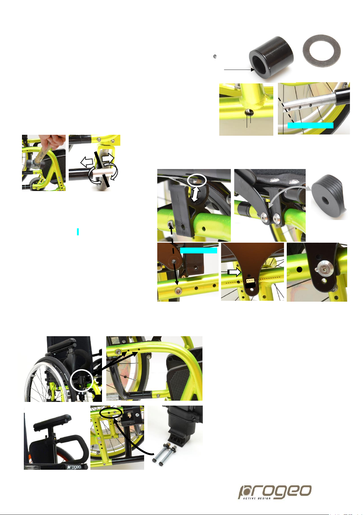
PARTICULAR NOTES
The spacers include a flanged IGUS buckle on one side only.
This flange prevents the contact between the aluminium parts on the
junction. Pay attention to this aspect.
Between some junction frame/crossbar, there may be an IGUS washer
to compensate a possible gap. When assembling the parts, make sure
you put these washers where they were originally located.
The connection tubes have three holes on the side of the rear frame
and they are meant for the different frame lengths. In some case, only for
the lower tube and only if the frame becomes short (thus, after removing
all spacers), due to the contact with the curved part of the frame, the tube
may not reach the point where the holes are aligned. Should that happen,
you have to round off the lower side corner of the tube end just enough.
If the frame are hard to remove, you can use a mallet.
If the connection tunes are hard to slide, you can use a mallet or you can use a
pin through one free hole and proceed with a turn-and-pull or turn-and-push
movement.
Sometimes, a nut that fix the seat canvas to
the seat tube interferes with the crossbar
support. Should that happen, fix the support
through another hole and fix the side guard
support adding a spacer for Ø 25 mm tube +
bolt, washer and nut.
If you change the frame to long frame, the front
fixing point of the side guard support will
correspond to the bolt fixing the frame to the
connection tube.
It is not advisable to use such point because
the inner tube may not be properly tighten and
it may create some play on the frame.
Therefore, you have to change the point where
to fix the side guard support.
To do that, first, fix the front side of the side guard support (together with the crossbar support or separated according
to the case). Turn the side guard support until aligning its fixing point to the frame’s axis. Position the crossbar support,
open the crossbar and let it lock on the four supports. Drill a 5 mm hole through the frame. Finally fix the parts.
Should the wheelchair be equipped with Flip-up
armrests, the adjustments remain the same.
You have to fix the front support of the armrest
through one of the two holes ahead of the one fixing
the frame to the connection tube.
The Flip-up armrest is depth adjustable.
Should the wheelchair be equipped with Desk
armrests, the armrest support is fixed through two
Ø 8 mm holes on the upper side of the rear frame.
To make the system stable, the fixing bolts pass
through two cylindrical spacers.
While adjusting the frame length, you always need
to remove the armrest support and their cylindrical
spacers.
The connection tube is fixed through the same
holes. If, after adjustment, one or both holes on the
tube were still Ø 6 mm, just pass the holes with an
8 mm drill pin.
Holes not aligned
Possible rounding off
Not advisable
Flanged
IGUS
buckle
IGUS washer
Table of contents
Other progeo Wheelchair manuals

progeo
progeo EASY TILT User manual

progeo
progeo Exelle User manual

progeo
progeo Junior User manual

progeo
progeo TEKNA ADVANCE Series User manual

progeo
progeo Joker User manual

progeo
progeo JOKER EVOLUTION User manual

progeo
progeo Exelle User manual

progeo
progeo Tekna Tilt User manual

progeo
progeo EGO Series User manual

progeo
progeo DUKE User manual

progeo
progeo ego User manual

progeo
progeo JOKER R2 User manual

progeo
progeo VARIO CARBON User manual

progeo
progeo Physio Air User manual

progeo
progeo JOKER JUNIOR 2.0 User manual

progeo
progeo YOGA User manual

progeo
progeo TEKNA TILT 2.0 User manual

progeo
progeo JOKER Series User manual

progeo
progeo YOGA User manual

progeo
progeo Basic Light User manual


