progeo TEKNA ADVANCE Series User manual

REHATEAM s.r.l.—vicolo Negrelli 5—31040 Castagnole di Paese TV - www.rehateamprogeo.com Service Manual TEKNA ADVANCE 1
SERVICE MANUAL
ENGLISH
S E R V I C E M A N U A L
TEKNA ADVANCE
TEKNA ADVANCE
with swing away, removable footplates
Rev. 0 - 06/05/2020

REHATEAM s.r.l.—vicolo Negrelli 5—31040 Castagnole di Paese TV - www.rehateamprogeo.com Service Manual TEKNA ADVANCE 2
SERVICE MANUAL
TEKNA ADVANCE
TEKNA ADVANCE
with swing-away, removable footplates
GENERAL WARNINGS
ANY ADJUSTMENT CAN BE CARRIED OUT EXCLUSIVELY BY QUALIFIED
AND AUTHORIZED BY REHATEAM® PERSONNEL.
It is forbidden to carry out any modifications, even when possible, to the original
design.
Any adjustments and/or any modification that is carried out by non-authorized
personnel will immediately void the warranty on the product and it relieves
RehaTEAM® from any responsibility on any malfunctioning and/or damage due
to such adjustments/modifications.
Always contact RehaTEAM® and its technicians for any non-standard
requirements or modifications to allow them to evaluate such modifications and
verify that they will not compromise the normal and safe use of the wheelchair.
Any modification of the original parameters and set up could seriously
compromise the safe operation of the wheelchair causing damage to both the
user and the wheelchair itself.
After every adjustment made to the wheelchair, check carefully that all parts are
correctly fixed. Check that all screws and nuts are tightened and that all moving
parts are functioning correctly.
After any adjustment, always test the wheelchair before giving the product to
user and/or his/her attendant.
RehaTEAM® disclaims any responsibility for damage to the product or the peo-
ple due to any modification that is not properly performed or that, in any case,
does not guarantee safety to the user.

REHATEAM s.r.l.—vicolo Negrelli 5—31040 Castagnole di Paese TV - www.rehateamprogeo.com Service Manual TEKNA ADVANCE 3
SERVICE MANUAL
Page adjustment
04 FRONT HEIGHT 1 Caster on fork
05 FRONT HEIGHT 2 Standard fork and axle
06 FRONT HEIGHT 3 Sliding the fork support (not for version with swing away footplates)
07 FORK ANGLE 1 System with hexagon
08 FORK ANGLE 2 System with spirit level
09 FORK ANGLE 3 Fork support V-Design
10 FORK ANGLE 4 Fork support V-Design 2.0
12 DIRECTIONALITY
16 REAR HEIGHT
17 SETTING (point of balance)
18 SIDE GUARD
20 SIDE GUARD Removable with blade system
22 CAMBER AND CONVERGENCY
24 BRAKE WITH PLATE OF SUPPORT
26 BRAKE WITH CLAMP
27 BRAKE SPACING
28 FOOTPLATE DISTANCE
29 ONE PIECE FLIP-UP PLASTIC FOOTPLATE
31 ONE PIECE FLIP-UP ALUMINUM FOOTPLATE
33 ONE PIECE FLIP-UP CARBON FOOTPLATE
35 ONE PIECE PLASTIC FOOTPLATE WITH AUTOMATIC CLOSURE
37 ONE PIECE ALUMINIUM FOOTPLATE WITH AUTOMATIC CLOSURE (COMPACT)
38 FRONT FRAME JOINING SYSTEM
39 DOUBLE FOOTPLATE
40 BACKREST HEIGHT
41 BACKREST ANGLE
42 QUICK RELEASE AXLE (rear wheel)
43 SEAT WIDTH ENLARGEMENT
45 FOOTPLATE FRAME LOCKING POSITION (only for version with swing-away footplates)
TEKNA ADVANCE
TEKNA ADVANCE
with swing-away, removable footplates

REHATEAM s.r.l.—vicolo Negrelli 5—31040 Castagnole di Paese TV - www.rehateamprogeo.com Service Manual TEKNA ADVANCE 4
FRONT HEIGHT 1
(caster on fork)
The entity of the adjustment obviously depends on the caster and fork’s sizes.
Screw off the bolt Vwhile holding the other.
Remove the axle P.
Position the caster to another hole, insert the axle and fix the bolt Vholding the one
on the other side.
Pay attention to the spacers between caster and fork.
SERVICE MANUAL
V
V
P
It is advisable to spread a
drop of mild lock thread
glue on the bolts V.
V
Standard
version
Versione with
Integrated bearings
Versione with
V-design support
Fork
height
Sport –2 holes –h. 88
Small –3 holes –h. 112
Medium –5 holes –h. 152
Long –4 holes –h. 178
Holes intervals –12,7 mm
Fork
height
Holes intervals –12,7 mm
Sport –2 holes –h. 100
Small –3 holes –h. 115
Medium –5 holes –h. 170
Fork
height
Sport –2 holes –h. 88
Small –3 holes –h. 112
Holes intervals –12,7 mm

REHATEAM s.r.l.—vicolo Negrelli 5—31040 Castagnole di Paese TV - www.rehateamprogeo.com Service Manual TEKNA ADVANCE 5
FRONT HEIGHT ADJUSTMENT 2
(standard fork and axle)
SERVICE MANUAL
Only for forks with Ø 12 axle hole, it is possible to change the axle Pwith a longer one (usually 25mm longer).
To replace the fork axle, first you need to remove the fork from its support.
Remove the cap and, with a 19 mm tubular box spanner while holding the fork with one hand, screw off the locknut B.
Now, hold the axle in its point A (16 mm spanner), screw off the locknut Dand remove the axle.
Insert the new axle and firmly tighten it on the fork.
Similarly, you can change the fork with another of different size.
.
To get access to the nut D, it may be necessary to remove the wheel.
If the locknut Dis too hard to unscrew, warm it with a hot air blower.
When assembling the fork on the support, put the washer Cand then the locknut B. screw the locknut Bholding the fork. The correct
torque has to zero the vertical play while letting the fork smoothly swivel.
Remember that the front height adjustment can affect the seat inclination, so it is necessary to check and adjust the fork angle
B
C
P
A
D

REHATEAM s.r.l.—vicolo Negrelli 5—31040 Castagnole di Paese TV - www.rehateamprogeo.com Service Manual TEKNA ADVANCE 6
FRONT HEIGHT 3
Sliding the fork support
(not for version with swing away footplates)
SERVICE MANUAL
It is advisable to spread a
drop of mild lock thread
glue on the headless bolt C.
All the following fork supports are fixed to the frame with clamp system.
Once you loose the clamp, you can slide the support along the frame and change the front height.
Standard Support and Support with Spirit Level
Loosen the headless bolt Cand the two nuts B.
Slide the support upward or downward to the desired
height.
Check that the two bolts A are fully tightened.
There must not be any room between clamp and plate.
Fix the two nuts Dholding the bolt Aand screw the
headless bolt G.
Repeat the same operations on the other side making
sure the height is the same. The two front wheels must
be touching the ground.
V-Design and V-Design 2.0 supports
Loosen the two bolts Aand slide the support upward or
downward to the desired height.
Fix the two bolts A hard.
If, after loosening the two bolts the support is too hard
to move, remove the bolts, screw them from the inner
side of the support, put and hold a little plate or washer
between the two inner walls of the support and screw
each bolt in order to expand the clamp.
BC
STANDARD SUPPORT SUPPORT WITH SPIRIT LEVEL V -DESIGN SUPPORT V-DESIGN 2.0 SUPPORT
A
AAA
Remember that the front height adjustment can affect
the seat inclination, so it is necessary to check and adjust
the fork angle.
Expanding the clamp
clamp
V-DESIGN V-DESIGN 2.0
clamp
plate

REHATEAM s.r.l.—vicolo Negrelli 5—31040 Castagnole di Paese TV - www.rehateamprogeo.com Service Manual TEKNA ADVANCE 7
FORK ANGLE 1
system with hexagon
SERVICE MANUAL
You can now turn the fork support (and the fork itself) clock or anti clock wise within the
limits given by the support’s slot Aagainst the bolt V. within such limits you will have to
find the correct angle: the fork has to be perpendicular to the ground.
You can reveal the perpendicularity using a spirit level leant against the cylinder of the
fork support as shown in the picture, or you can turn the fork. In this last way, the caster
should evenly touch the ground all around the clock.
When you find the correct angle, you have to insert the nut Dwith two of its two sides
perfectly aligned with those of the slot A, but without moving the fork support.
The adjustment nut Dhas two holes. Each hole gives 6 different positions, so, in total
there are 12 positions.
Insert the nut on the bolt using one hole and turn it to try the 6 positions. You cannot
position the nut if the bolt is touching either side of the slot.
When you find the coinciding position, push the nut into the housing and tighten the
bolt. Should no position allow for the perfect alignment, try the other hole of the nut and
repeat the same operations.
DO NOT adapt the position of the fork support to the nut, this way you actually change
the fork angle.
If you cannot reach the perpendicularity within the range given by the slot A, remove
the bolt V1 and remove the fork paying attention to which of the two holes Aor Bit was
fixed to.
Assemble the fork using the other hole and tighten the corresponding bolt.
Repeating the same operations above mentioned, adjust the fork angle and position
the nut.
Finally, tighten the bolts Aand Bhard.
If, in the coinciding position, the nut is leaning out of the support, it is advisable, in or-
der to have a better hold, to reverse its position (of course, using the same hole); this
way, the nut will fully be located within the support housing.
It is advisable to spread a
drop of mild lock thread
glue on the bolts V and V1.
nut leaning out nut fully in housing
WORK ON A FLAT AND EVEN SURFACE.
The adjustment is the same for both Exelle and Exelle Vario. The pictures show the assembly on the Exelle Vario. Note that, differently from
the models Exelle/Exelle Vario, the support is assembled facing backward; however, in some cases in alcuni casi, it is possible to assemble
it facing frontward.
Unscrew the bolt V that fixes the nut D. Remove the nut Dbut leave the bolt on completely. You should not loosen the other bolt, in fact it
will hold the fork while performing the adjustment.

REHATEAM s.r.l.—vicolo Negrelli 5—31040 Castagnole di Paese TV - www.rehateamprogeo.com Service Manual TEKNA ADVANCE 8
FORK ANGLE 2
system with spirit level
SERVICE MANUAL
WORK ON A FLAT EVEN SURFACE.
Whenever the seat height is changed or as periodic maintenance, check the fork angle and, if necessary, adjust it in order to have the fork
axis perpendicular to the ground.
The fork adjustment system is based on the combination of two rings (A1, A2) with inclined plane.
The upper ring A1 works on the fork support while the ring A2 works on the ring A1.
A1
A2
1 2 3 4 5 6
A2 A1
Bearing unit detached from the fork support.
Pictures 1, 2 and 3 show that the upper axle of the bearing unit, rotating on
the lower axle (that allows the fork to turn), changes inclination thanks to the
inclined plane of the ring A2. Pictures 4, 5 and 6 show three different inclina-
tions of the ring A1 keeping A2 still. Each combination of the position of
these two rings gives a different angle to the fork axis.
To carry out the adjustment, start with loosening the nut B.
To do so, you have to align external hole Cand the internal hole C1 of the adjustment axle and insert a steel (or an Allen key) through them
(in the picture, the two parts are separate to make see the internal hole C1). With the pin inserted, you can turn the ring A2.
The nut Bhas to be loosened just enough to let the ring A1 move.
Do not loosen the Btoo much, otherwise the system will be instable and it will be very difficult to
adjust.
The play should be null or the minimum possible.
To turn the ring’A1, insert a pin (or an Allen key) through the hole D.
Now, while keeping both pin inserted, turn ring A2 (consequently the fork) without moving the ring
A1.
While performing this operation check how the bubble of the spirit level Lmoves.
If, for the whole rotation of the ring A2. the bubble never passes through or close to the circle, it
means you need to change the position of ring A1.
HOLD A1
TURN A2
(fork)
B
C
C1
A1 A2
D
L
Follows next page

REHATEAM s.r.l.—vicolo Negrelli 5—31040 Castagnole di Paese TV - www.rehateamprogeo.com Service Manual TEKNA ADVANCE 9
FORK ANGLE 2
system with spirit level
SERVICE MANUAL
Follows next page
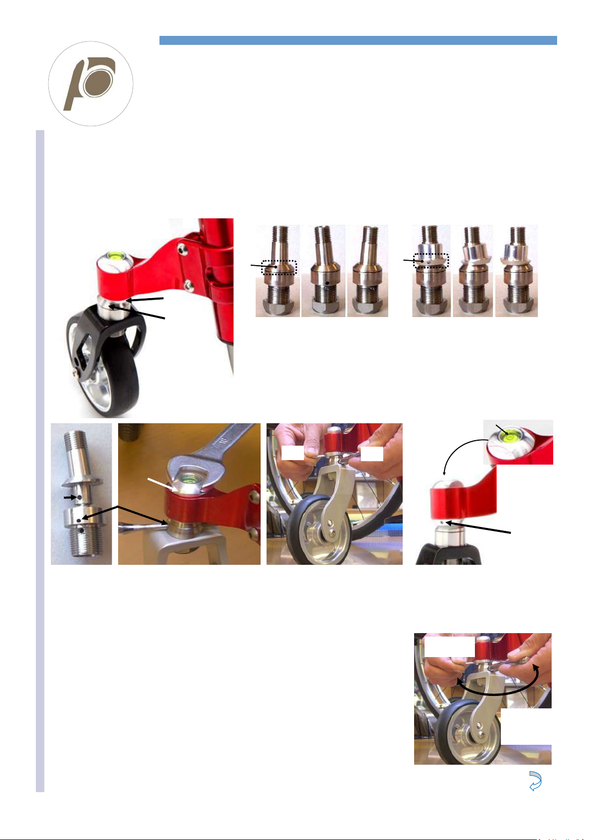
Turn the ring A1 a little in either direction and repeat the same operation above explained.
You have to repeat this procedure until the position of the ring A1 allows the bubble to be very
close to the circle of the spirit level.
At this stage, it is possible to turn both the ring A1 and the fork together with very small move-
ments until the bubble gets within the circle.
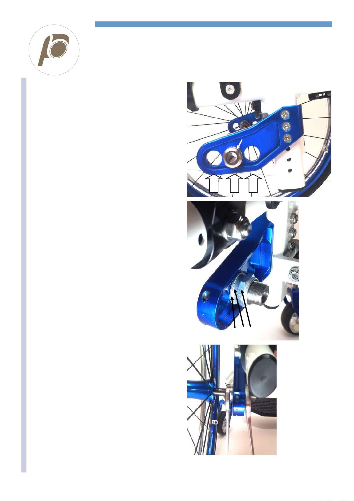
Check the nut Bis not too loose (to prevent instability of the system) and not too tighten (in this
case the ring A1 will not move).
To tighten or loosen the nut Bduring adjustment, you can usually use your finger (if it is too hard,
you can use the spanner).
As mentioned at the beginning, the adjustment is necessary whenever modifying the seat inclina-
tion (front and/or rear height).
In such cases, the entity of the adjustment is not much, in other words, the point you start from is
very near the goal. Therefore, the rotations of rings A1 and A2 will be by just a few degrees (clock
or anticlockwise).
When you reach the correct angle, fix the system. Both pins should be inserted.
With one hand, hold the fork and the pin on the hole of the ring A1 to control its position.
With the other bare hand, screw up the nut Bas much as possible while checking the spirit level.
Now gradually tighten the nut Bwith the spanner.
If, while tightening, the bubble moves away from the circle, it means that the fork has moved.
To compensate such unwanted movement, turn the fork in the nut loosening direction and check
the bubble.
It may seldom happen, though, that even the ring A1 moves while tightening. In that case, adjust it
back.
Make sure the bubble is within the circle and then fully tighten the nut B.
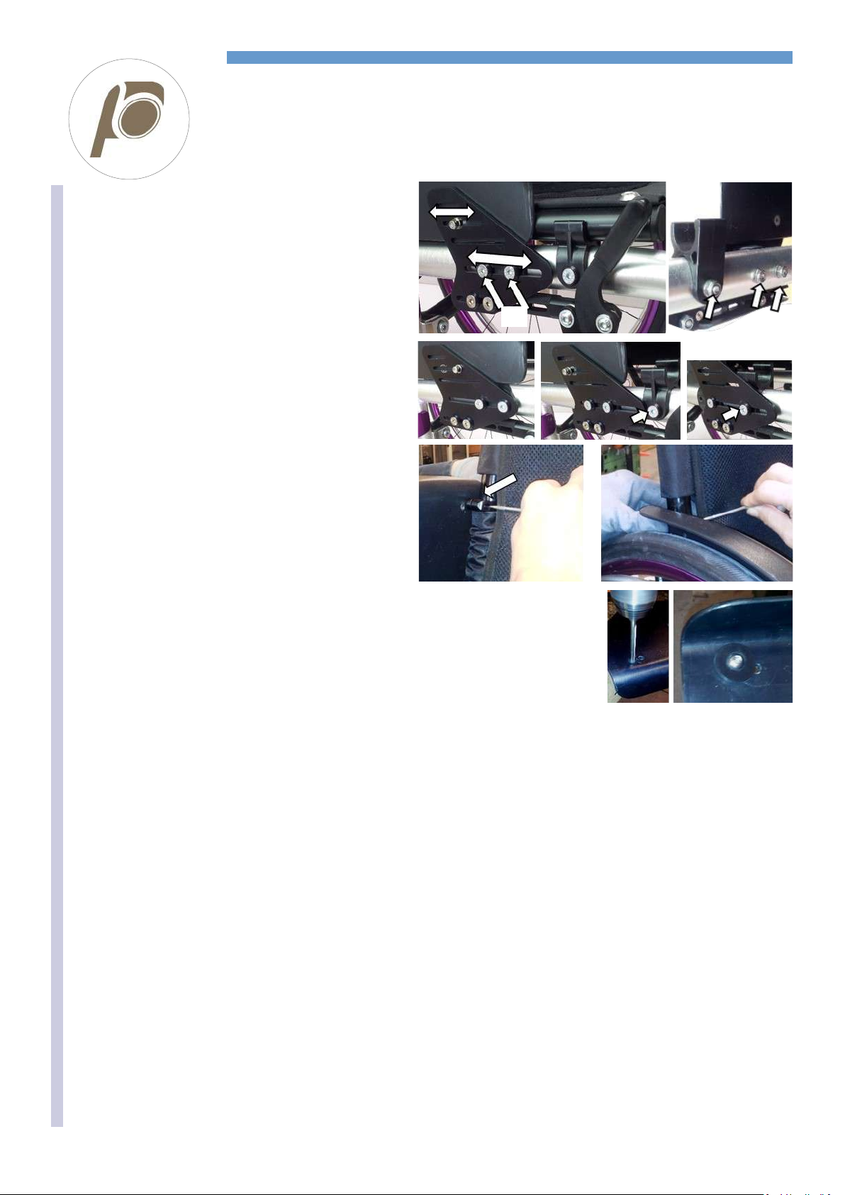
To reduce the risk of scratching the paint of the support around the nut, it is advisable to stick a
shaped piece of female Velcro on the spanner.
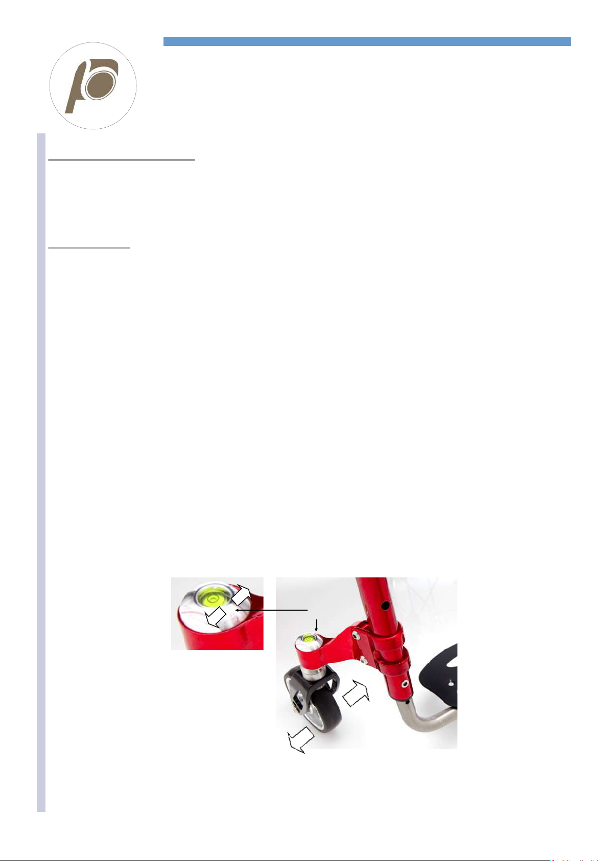
This adjustment system often allows two different combinations A1/A2 with the same correct result
(axis perpendicular to the ground).
The two positions, even though they both give the 90° to the ground, are not exactly the same, in
fact the distance between the rotation axle of the fork and the frame is different.
This means that you have to adjust the two forks symmetrically and this surely helps to adjust the
“second” fork. Just have a look where the hole of the ring A1 is with respect to the frame and sym-
metrically start form that point on the other fork to adjust.
Furthermore, the two combinations (when possible) allow solving the problem of interference be-
tween front wheel and footplate or tube. If the first found position results with such interference,
just try the second position that may be better.
Differently, it will be necessary to change the size of front wheels or footplate position or the seat
inclination (front or rear height).
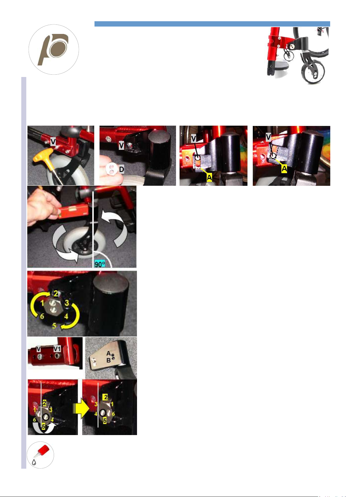
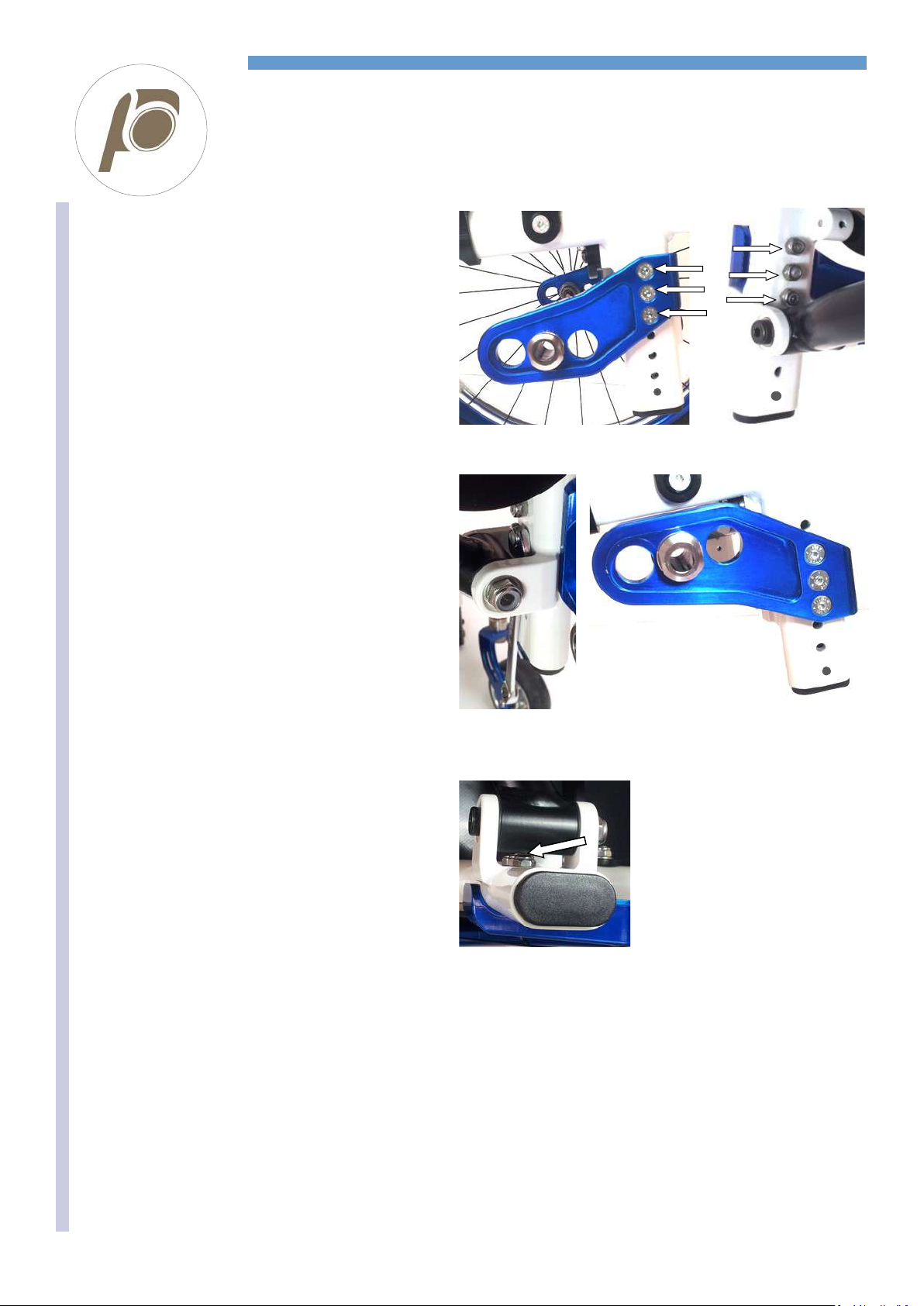
Change position of A1
TURN A2
(fork)
The two white arches show the possi-
ble different positions of the fork rota-
tion axis (both at 90° to the ground).
The difference can be a few millimetres
You have to adjust the two rings A1
symmetrically.
The two white and the two black circles
show the two possible positions.
It is advisable to pread a
drop of mild lock thread
glue on the nub B.

REHATEAM s.r.l.—vicolo Negrelli 5—31040 Castagnole di Paese TV - www.rehateamprogeo.com Service Manual TEKNA ADVANCE 10
FORK ANGLE 2
system with spirit level
SERVICE MANUAL
When adjusting the fork angle avoid:
Working on ring A1 and A2 (fork) together form the beginning –this does not give any precise point of reference (as ring A1 does in one
any position that you can change if not correct).
Thinking that the front wheel must be orientated as when driving the wheelchair (the fork is part of the adjustment).
Keeping the nut Btoo loose while finding the correct angle.
Directionality check.
After adjustment, the wheelchair has to be tested to verify if it goes straight.
See also sheet DIRECTIONALITY.
Check both casters are touching the ground, if not, adjust their height.
If the wheelchair turns right or left, it means that you need to correct the adjustment.
If it turns right: the right fork is tilted inward (internal) or the left fork is titled outward (external).
If it turns left: the left fork is tilted inward or the right fork is titled outward.
Check which of the two to adjust.
The adjustment will be really of minimum entity.
The necessary rotation of either A1 or A2 (fork) is tiny.
Loosen the nut Bas little as necessary.
Proceed with the adjustment making the bubble slightly move: - inwardly with respect to the wheelchair if the fork is external;
- outwardly with respect of the wheelchair if the fork is internal
The bubble does not necessarily be perfectly concentric with the circle of the spirt level.
It is enough that it is within the circle or even adjacent.
The spirit level is, at origin, glued to the axle, therefore, there is a minimum tolerance while centring it.
After adjustment, the wheelchair has to go straight.
2
1
2
1
B

REHATEAM s.r.l.—vicolo Negrelli 5—31040 Castagnole di Paese TV - www.rehateamprogeo.com Service Manual TEKNA ADVANCE 11
FORK ANGLE 3
V-Design fork support
SERVICE MANUAL
WORK ON A FLAT EVEN SURFACE.
Whenever the seat height is changed or as periodic mainte-
nance, check the fork angle and, if necessary, adjust it in
order to have the fork axis perpendicular to the ground.
To loosen the system:
loosen the two bolts A, the two headless bolts B1 B2 and
the nut C.
To adjust the fork:
Turn the fork axle, clock or anticlockwise, until the perpen-
dicularity, 90° to the ground.
To make this operation easy, it is advisable to slightly tight-
en one of the two bolts Aso that to allow for the fork axle
rotation and keeping it in position after moving it.
You can measure the perpendicularity with the help of a
square (or similar) vertically aligned to the caster; the caster
has to be turn 90° with respect to the driving direction.
Alternatively, turn the fork by 360°: during the full turn, the
wheel has to touch the surface in all positions.
To fix the system proceed with the following sequence:
• Tighten the two bolts Aalternating them each quarter of
a turn in order to allow for an even clamp torque.
• Tight and hold bolt Dand tighten the nut C
• Finally, tighten the two headless bolts B1 B2
Directionality
Try the wheelchair out and verify it goes straight. See also
DIRECTIONALITY
A
D
C
B2 B1
90°
B1
A
B2 C
It is advisable to spread a
drop of mild lock thread glue
on the headless bolts B1 B2.
V-Design short V-Design fork axle

REHATEAM s.r.l.—vicolo Negrelli 5—31040 Castagnole di Paese TV - www.rehateamprogeo.com Service Manual TEKNA ADVANCE 12
SERVICE MANUAL
It is advisable to pread a
drop of mild lock thread
glue on all grab screws G.
WORK ON A FLAT AND EVEN SURFACE
Whenever the seat height is changed or as periodic maintenance, check the fork angle and, if necessary, adjust it in order to have the fork
axis perpendicular to the ground.
The adjustment is possible by means of the four grab screws G1, G2 and G3 that make the axle Pturn on the fulcrum F.
Rotation when
screwing
G1 and G4
Rotation when
screwing
G2 and G3
G1
F
G3
G2
G4
P
To turn the fork
backward
Loosen G2 and G3.
Screw G1 and G4
Perpendicularity
You can check the perpendicu-
larity with the help of a square
(or similar) vertically aligned to
the caster turned 90° with re-
spect to the driving direction of
the wheelchair
To turn the fork
fronward
Loosen G1 and G4.
Screw G2 and G3
To adjust the fork, once you know the direction (frontward or backward) towards which it is necessary to move the fork’s axle, proceed as
above-mentioned until reaching the correct angle.
You can also measure the perpendicularity by turning the fork by 360°: during the full turn, the wheel has to touch the surface in all posi-
tions.
If a headless bolt results hard to unscrew, DO NOT FORCE IT, but try to loosen the other two first.
If the fork’s axle (the axle P) results hard to move, slightly loosen the bolt of the fulcrum F(remember to screw it after adjust-
ment).
Once you reach the correct angle, screw all three headless bolts all the way down to the axle P, but without tightening.
In order to fix the system, tighten first one and then the other less than a quarter of a turn at once, the grab screws G2 and G4 (the front
ones) checking the perpendicularity; in fact, it may slightly change during this phase.
Should that happen, correct the angle proceeding in the same manner.
When you have tightened both headless bolts G2 and G4, you can tighten the headless bolt G1 and G3.
Check the perpendicularity again and, if necessary, correct it.
FORK ANGLE 4
Fork support V-Design 2.0
G1
90°
F
G4
G3
F
G2
G1
G3
G2
G4
F

REHATEAM s.r.l.—vicolo Negrelli 5—31040 Castagnole di Paese TV - www.rehateamprogeo.com Service Manual TEKNA ADVANCE 13
SERVICE MANUAL
DIRECTIONALITY
A very important aspect of any wheelchair is its directionality.
To check if the wheelchair goes straight, sit on it, push it and let it go until it stops.
If something is wrong, the slower the wheelchairs moves forward (momentum close to nothing), the more likely it turns right or left. There-
fore, if no or irrelevant turn occurs, the wheelchair is properly adjusted.
Cause Reason Solution
SURFACE The surface where the test is being performed is not even
and flat
Test the chair on even and flat surface
REAR WHEELS
The rear wheel are not equally inflated Inflate both tyres at the same pressure
The tyres of the two rear wheel are different or differently Change the tyres
The rear wheels are not adjusted at the same height Adjust the rear wheel height
The camber of right and left wheels are different or differ-
ently adjusted
Adjust the camber.
The wheel, when turning, touches the side guard or the
brakes
Fix or replace the side guard. Add spacer on the
receiver. Adjust the brake.
The wheels doe not turn smoothly Clean or change the bearings
FRONT WHEELS The casters are not adjusted at the same height Adjust the front wheels at the same height
The tyres of the two front wheels are different or differently Change the wheels
The fixing bolts of the fork/fork support/clamp are loosened Check and tighten all fixing bolts
The caster does not turn smoothly Clean the bearings.
Either or both forks are not adjusted so as their axis is per-
pendicular to the ground.
Adjust the fork axis inclination.
FOOTPLATE The footplate tubes are adjusteD at different height. Adjust the tubes at the same height
If the wheelchairs does not go straight, in most cases the reason
is the fork angle adjustment.
However, before working on the fork angle adjustment, check all
the points above mentioned.
First, make the test along a flat even surface to check the direc-
tionality.
1 The correct adjustment has both forks perpendicular to the
ground, that is, their axis at 90°.
2 If the wheelchair TURN RIGHT, the cause is one or more of
the following:
The RIGHT fork is tilted inwardly and/or backward
The LEFT fork is tilted outwardly and/or frontward
3If the wheelchair TURN LEFTT, the cause is one or more of
the following:
The LEFT fork is tilted inwardly and/or backward
The RIGHT fork is tilted outwardly and/or frontward
90° 90° 90° 90°
1
2
3
Follows next page

REHATEAM s.r.l.—vicolo Negrelli 5—31040 Castagnole di Paese TV - www.rehateamprogeo.com Service Manual TEKNA ADVANCE 14
SERVICE MANUAL
DIRECTIONALITY
ADJUSTING THE DIRECTIONALITY
Check that the two forks are perpendicular to the ground. If they are
not, proceed with the adjustment of the fork angle following the instruc-
tions on the sheet FORK ANGLE ADJUSTMENT.
If both forks axis are correct but the wheelchair still turns right or left, it
means that the latitudinal angle is not perfect.
This may be due to hit, to improper pressure exercised on the fork or
its support, or to a tiny imperfection among all parts fixed together due
to their manufacturing tolerances.
System with hexagon
This adjustment systems does not allow for latitudinal (camber) adjust-
ment, the only way to correct the angle is to put a sort of spacer be-
tween the upper or lower side of the fork support and the plate where it
is fixed. The spacer can simply be a piece of plastic strapping (0.5 mm
–1 mm thick).
To incline the fork internally 1, position the strapping on the upper side
of the fork support.
To incline the fork externally 2, position the strapping on the lower side
of the fork support.
Other systems
Make sure the two bolts Aare well tightened.
In fact, if they are not fully tightened, the clamp will not take a proper
hold on the frame and the support position may not be precise.
Then, continue according to the type of system.
With spirit level
See sheet “fork angle 2” – directionality.
With fork support V-Design
If the operation above mentioned is not satisfactory, consult Rehateam
s.r.l..
With fork support V-Design 2.0
Loosen all four grab screws G, remove the bolt Fand slide off the fork
complete with the axle P.
The axle has two side hollows Bwhere you have to cast the flat inserts
C0 or the 1° titled inserts C1 that are recognizable thanks to two dots.
With the flat inserts C0, the axle keep its original inclination.
With the tilted inserts C1, the axle tilts by 1° right or left according to
how to cast them in the hollows—see images.
Note: you can cast the inserts only as indicated in these images.
For the adjustment of the fork angle,
see chapters “fork angle”.
Plastic strapping
1
2
1 2
System with hexagon
A
System with spirit level V-Design V-Design 2.0
G1
G3
G2
G4
F
V-Design 2.0 B
P
0° XY1°
Y X X Y
X Y Y X
0° 1° 1°
P P P
C0 C1
Follows next page

REHATEAM s.r.l.—vicolo Negrelli 5—31040 Castagnole di Paese TV - www.rehateamprogeo.com Service Manual TEKNA ADVANCE 15
SERVICE MANUAL
DIRECTIONALITY
Mounting back the fork of the system V-Design 2.0.
Once you have casted the inserts C0 or C2, it is advisable to try to screw the
bolt Fto check there is no difficulty. Sometimes, in fact, the holes of the inserts
may have working burr that make the bolt hard to go through.
To mount the fork unit. Insert the axle Pin the fork support paying attention to
the orientation of the same axle. In fact, the axle is not straight, but it shows a
bend.
Such bend must be facing to the rear of the wheelchair.
Insert and screw the bolt Fwithout tightening it much (it is enough to screw it
up to stop).
Adjust the fork angle —see sheet “fork angle 4”.
Note.
This type of adjustment can take place even at original assembly, therefore,
you may find the inserts C0 on one axle and C1 on the other, for instance.
The wheelchair is not supplied with supplementary inserts, therefore, it will be
necessary to order them when needed.
For the adjustment of the fork angle and the removal of the fork support,
see chapters “fork angle” and “fork support position”
F
P
C0 or C1 C0 or C1
SIDE VIEW
P
REAR FRONT
C0 or C1
Axles without inserts
Until 2019 the axles had no inserts C0 or
C1. There were 0°, 1°rh and 1°lh axles. To
adjust the directionality, it is necessary to
change the axle.

REHATEAM s.r.l.—vicolo Negrelli 5—31040 Castagnole di Paese TV - www.rehateamprogeo.com Service Manual TEKNA ADVANCE 16
SERVICE MANUAL
REAR HEIGHT
Adjustment every 1.5 cm
You can adjust the rear height by changing the position of the
plate Awith respect to the adjustment post.
Remove the three bolts Band nuts Cand remove the plate A.
If a nut is close to the crossbar joint, you can let the spanner pass
between the adjustment post and the crossbar joint.
Position the plate Pat a different height and fix it.
In order to obtain other heights, you can reverse the right plate
with left and vice versa, so that you orientate them upward or
downward.
Warning: also the receiver turns 180°, thus, if it is 2° or 4°, the
camber will result opposite! Therefore, adjust the camber/
convergence, too.
If you decrease the rear height, remove the side guard first. In
fact, the rear wheel will touch the side guard.
After adjustment, adjust the side guard and the brake, too.
Remember that the adjustment of the rear height affect the seat
inclination, therefore it is necessary to check/adjust the fork an-
gle, too.
Info: the bolts Bare made-to-measure. That is necessary to pre-
vent interference between the point of that bolt and the crossbar
rotation tube where this would happen with longer (even 1 mm)
bolts.
A
B
C
Spanner between
crossbar joint and post.
Plate orientated upward and
assembled in the highest
possible position
(minimum rear height.

REHATEAM s.r.l.—vicolo Negrelli 5—31040 Castagnole di Paese TV - www.rehateamprogeo.com Service Manual TEKNA ADVANCE 17
SERVICE MANUAL
SETTING (point of balance)
Three possible settings: 1 PRUDENTIAL 50mm
2 STANDARD 75 mm
3 ACTIVE 100 mm
Adjustment.
Remove the receiver Aand nut B.
Move the receiver to one of the other two positions.
Insert the toothed washer C, the spacer Dand then the nut B.
The spacer Dis present to allow the nut Bto be more accessible when
holding grip on it with the spanner.
Advice: sometimes, when tightening the receiver very hard, you may
deform the receiver and thus impede the quick release axle to pass
through it. Therefore, before tightening the receiver hard, insert the rear
wheel (or just the quick release axle) into the receiver but leaving
enough room to get hold of it with the spanner.
With 2° or 4° receivers, you have to adjust the camber and the conver-
gence, too.
If you move the setting forward, it is necessary to remove the mud-
guard (not necessary if straight guard) before putting the wheel on. In
fact, the wheel will touch the mudguard.
After adjustment, adjust the side guard and the brake, too.
Remember that the adjustment of the setting can affect the seat incli-
nation; therefore, it is necessary to check/adjust the fork angle, too.
1 2 3
A
C D B
Stighten the
receiver with the
axle in.

REHATEAM s.r.l.—vicolo Negrelli 5—31040 Castagnole di Paese TV - www.rehateamprogeo.com Service Manual TEKNA ADVANCE 18
SERVICE MANUAL
SIDE GUARD
Standard rear frame
After any adjustment of the rear wheel, you will have to adjust the position of the
side guard accordingly.
You should adjust the side guard at approximately 5 mm from the tyre. It is fixed to
the frame in two points: to the backrest tube with a ring Athat can slide along the
same tube; to the plate of support B.
If the side guard is straight, you can decide to modify it or not.
A
When you decrease the rear height, you have to move the side guard up.
1. After the rear height adjustment, remove the bolt and nut C1 C2.
2. Loosen the bolt D, slide the side guard upward even beyond the necessary and
temporarily fix it just enough to let it stay where you position it.
3. Put the rear wheel on and position the side guard at approximately 5 mm from
the tyre and parallel to it. Remove the rear wheel, fix the bolt Dand put the rear
wheel back on.
4. While keeping the side guard at 5 mm from the tyre, from the outside of the plate
of support B, mark the point where you will have to drill a new hole (however,
check whether you can use the same hole).
5. To do so, use a pointed tool and let it through the slot of the plate. It is advisable
to mark it in the middle of the slot. If the rear height adjustment is remarkable,
you may need a new side guard.
6. Drill a 5 mm hole on the mud guard where just marked.
7. Countersink the hole.
8. Insert the bolt, washer and nut C1 C2 and fix the side guard.
9. Adjust the brake.
B
When you increase the rear height, you have to move the side guard down.
1. After the rear height adjustment, remove the bolt and nut C1 C2.
2. Lean the side guard on the outside of the plate of support.
3. Loosen the bolt D just enough to move the side guard, put the rear wheel on and
position the side guard at approximately 5 mm from the tyre. Remove the rear
wheel and fix the bolt D.
4. Draw a line on the lower side of the side guard considering that, when finally
assembled, it will lean on the spacer of the plate of support. The side guard can-
not go down beyond that spacer.
5. Remove the bolt Dand remove the side guard.
6. Saw the side guard along the line you have just drawn and round off the edge
with a blade of a scissor or with fine sand paper.
7. Assemble the side guard and slightly fix it with the bolt D.
8. Continue following the points 3 to 9 of the adjustment A.
Follows next page
A
B
D
C1
B
AC2
A

REHATEAM s.r.l.—vicolo Negrelli 5—31040 Castagnole di Paese TV - www.rehateamprogeo.com Service Manual TEKNA ADVANCE 19
SERVICE MANUAL
SIDE GUARD
Standard rear frame
C
When you change the setting, you have to move the side guard
frontward or backward according to the new position of the rear
wheel, but the height of the side guard remains the same.
1. After the setting adjustment, remove the bolt D.
2. Loosen the two bolts and nuts E1 E2 fixing the plate of support
Bto the frame.
3. Put the wheel on and slide the plate Bforward or backward.
Position the side guard at 5 mm from the tyre. If necessary, you
can loosen the bolt and nut C1 C2 and slide the side guard or
you can also fix the plate Bover the seat tube support Fwith
the bolt and nut G1 G2.
4. Fix the two bolts and nuts E1 E2 (o E1 E2 + G1 G2).
5. You have now to drill a new hole for the bolt D. With a pointed
tool through the hole of the ring A, make a mark on the side
guard.
6. Drill a 6 mm hole
7. Insert the bolt and washer Dand fix the side guard. Make sure
to fix bolt and nut C1 C2 , too.
8. Check and if necessary adjust the brake.
D
When you change both the rear height and the setting, you have to move the side guard up or down and forward or backward.
1. After the rear wheel height and position adjustment, remove the bolt Dand the bolt and nut C1 C2. This way you remove the side
guard.
2. Put the wheel on.
3. Adjust the brake by moving the plate of support Balong the frame (see points 2 and 3 of the adjustment C).
4. Position and hold with one hand the side guard at approximately 5 mm from the tyre and parallel to it if (you can lean the side guard on
the outside of the plate of support as in adjustment B).
5. You have now to drill a new hole for the bolt D, thus, while holding the side guard in position, make a mark on the side guard with a
pointed tool through the hole of the ring A.
6. Drill a 6 mm hole.
7. Insert the bolt and washer Dand fix the side guard.
8. Follow points 4 to 8 of adjustment A or Baccording to the adjustment.
9. If the slots of the plate Bdo not allow fixing the side guard, you may move it accordingly.
10.Finally check and, if necessary, adjust the brake.
E1 E2
C1
C2
G2
F
G1 G1
Mark where
to drill the
new hole
A
B

REHATEAM s.r.l.—vicolo Negrelli 5—31040 Castagnole di Paese TV - www.rehateamprogeo.com Service Manual TEKNA ADVANCE 20
SERVICE MANUAL
SIDE GUARD
Removable with blade system
After every adjustment of the rear wheel, you have to adjust the position of the side guard. You have to adjust the side guard at approxi-
mately 5 mm from the tyre. The side guard is fixed to three points on the blade Athat slides in the support Bfixed to the frame.
A C
A
A
Height adjustment: the blade Ashows, in its vertical side, a series of holes to fix the bolt Cthat inserts in the hollow Dof the support B.
Therefore, to change the height, just remove the bolt Cand screw it in another hole.
WARNING: do not tighten the bolt C excessively: it may damage the threaded hole until making it unusable.
Side guard modification: If one, the other or the combination of both adjustment above mentioned are not satisfactory, you can modify the
side guard.
Every side guard is shaped to measure according to the configuration of the wheelchair when originally assembled.
The shape of the side guard always allow for a reasonable good range of adaptation.
Note: if the side guard is straight, you can decide to modify it or not.
AWHEN YOU DECREASE THE REAR HEIGHT, you have to move the side guard up.
1. Remove the three bolts Hto take the side guard off the blade.
2. Position the side guard at approximately 5 mm from the tyre, always leant on the blade A. The bolt Con the blade must be inserted in the
hollow Dof the support.
3. While holding this position, mark the point where it is necessary to drill the first new hole (1 or 2; 3 is usually not accessible with the rear
wheel on).
4. To do so, use a point and let it through the accessible hole. If the rear height adjustment is remarkable, you may need a new sideguard.
5. Drill a 5 mm on the sideguard where you have marked it.
6. Countersink the hole.
7. Insert and screw the bolt H.
8. To drill the second hole on the side guard, follow instruction from 3 to 7.
9. To drill the third hole, remove the side guard, mark the point where to drill and follow instruction from 5 to 7.
E
D C
2
1
33
21A
B
It is advisable to spread a drop of
mild lock thread glue on the bolts E
and C. Follows next page
Table of contents
Other progeo Wheelchair manuals

progeo
progeo Exelle Junior User manual

progeo
progeo YOGA User manual

progeo
progeo MOTOTRONIK User manual

progeo
progeo Tekna Tilt User manual

progeo
progeo Junior User manual

progeo
progeo VARIO CARBON User manual

progeo
progeo NOIR 2.0 User manual

progeo
progeo Raptor User manual

progeo
progeo JOKER R2 User manual

progeo
progeo TEKNA TILT adult User manual

progeo
progeo VARIOTRONIC User manual

progeo
progeo EASY TILT User manual

progeo
progeo EXELLE VARIO Classic User manual

progeo
progeo ego User manual

progeo
progeo CARBOMAX User manual

progeo
progeo JOKER ENERGY User manual

progeo
progeo Joker User manual

progeo
progeo Exelle User manual

progeo
progeo Tekna Tilt User manual

progeo
progeo VARIO CARBON User manual