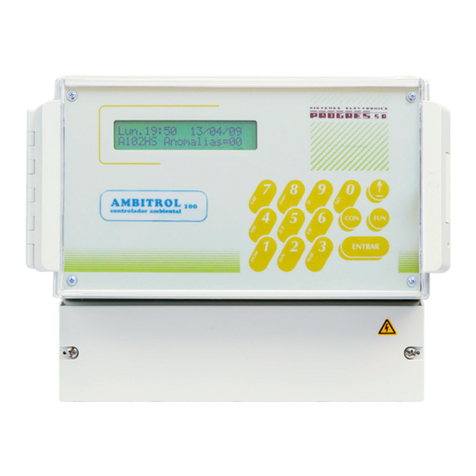
Progres Agronic User manual

1
INSTRUCTION
MANUAL
VERSION 2
INDEX
Sec. THEME Page
1. BASIC FUNCTIONAL DESCRIPTION 1
2. DIMENSIONS 3
3. INSTALLATION 3
3.1. Placing the unit 3
3.2. Connection 4
3.3. Guide to malfunctions 5
3.4. Enclosed information for the
installation options
6
4. TECHNICAL CHARACTERISTICS 7
5. USE 8
5.1 Functions 8
5.2 Configuration 8
5.3 Timings 8
5.4 Manual 9
5.5. Totals 9
5.6. Consultation 9
PRESENTATION
We wish to take this opportunity to thank you for
the confidence in us which you have demonstrated in
expressing interest or acquiring the Agrónic Filters.
This confidence, for our part, stimulates our
efforts to meet and surpass the expectations of our
clients to justify the traditional quality of our products.
This manual will explain the specification of the
equipment as well as its installation and use.
However, if after reading this you still have any
doubts, contact us and we will happily answer them.
1. BASIC FUNCTIONAL DESCRIPTION
is a controller for the automatic cleaning
of filter batteries with different possibilities of starting
and working.
There are 3 different models according to the
number of filters to control: for 6, 12 and 18 filters.
Models for 6 and 12 filters can be increased whenever
necessary, up to 18, sending them back to the factory.
Filter cleaning can be started by:
a) By a “drop in pressure”: Working whenever
the controller receives a signal from the differential
pressure gauge which controls the drop in pressure
between the input and outlet of the filters, as a
consequence of the dirt accumulated in them.
b) By “volume”: Working every certain volume of
filtered water. In this case, the controller must receive
signals from a volumetric impulse transmitter.
c) By “time”: Working every certain time of water
circulation through the filters (in this way, the
controller needs to receive the corresponding external
signal).
d) By a combination of the “drop in pressure”
with the “filtered volume” or the “ time that has gone
by” and in this way a minimum periodical cleaning is
guaranteed, if it has not been necessary to do it
before, due to an unexpected accumulation of dirt.
Once the cleaning order has been detected, the
different connected filters will be activated sequentially
(one after the other) by the controller. The duration of
the cleaning of every filter can be programmed
independently.

2
There is a timing which affects all filters equally:
the pause between filters. This timing is important to
recover pressures in the net and avoid overlapping in
the hydraulic valves.
Both a cleaning sequence and the outlets can be
started or stopped manually with the unit. The unit can
also be set at stop (deactivated).
The user can easily program all the parameter
and timing values of the controller.
The unit shows the state of the unit at all times,
indicating the filter that is working, whether it is
working, the state of the inputs and whether there is
any outlet which has been activated in a manual way
as well as showing whether the controller is at stop. It
also informs about the circulating instantaneous flow
and about the volume and time units that have gone
by since the last cleaning.
At the TOTALS function, the unit shows the
number of cleanings that have taken place due to a
“drop in pressure” and “volume” or “time”. The total
water volume, which has circulated through the filters
or the time it, has been working, since the last time it
was set at zero are also indicated.
The unit has the following inputs:
- For the differential pressure gauge which
detects the drop in pressure in the filters, (necessary
for the starts by “drop of pressure”),
- For the detection of water flow through the
filters with a signal that comes from a programmer,
calliper, etc., (necessary for the starts “by time” and
for the total of hours that the filter installation has been
working),
- For the volumetric impulse transmitter,
(necessary for the starts by “volume”, information
about the instantaneous flow and volume total of
filtered water),
- For the detection of breakdowns in the
installation,
- For different options.
A timing for detection delay can be assigned to
the inputs, in order to avoid inadequate signals.
There can be three types of outlet: at 24 Vac, at
12 Vdc and at 12 Vdc for latch valves (with two or
three wires) with low consume.
MODELS AND OPTIONS
-Models for 6, 12, 18 outlets.
-220 Vac version and 24 Vac outlets.
-12 Vdc version and 12 Vdc outlets.
-Version with the equipment provided in a box with
transparent cover.
-Version with the equipment prepared to build-in a
cupboard or a desk.
-Option with outlets for latch valves (with two or
three wires) and low consume. Due to the fact that this
version has a low consume of the unit and its
electrovalves, it is very suitable for those installations
which work with a battery and which do not have a
diesel engine or a solar cells to recharge it.
-Version for filters with cleaning and rinse. It can
have 2, 4 or 6 filters. Every filter uses three relays to
control the 5 necessary hydraulic valves. The
programmer will ask for every filter the cleaning and
rinsing time.
WARRANTY
The Agrónic filter controller meets all the norms set
by the EC.
The products created by PROGRÉS enjoy a two-
year warranty against all manufacturing defects.
Compensation for direct or indirect damage
caused by the use of the equipment is excluded from
the guarantee.
GRAPHIC OF A FILTER CLEANING SEQUENCE
-Example A- Without pause timing between filters.
Cleaning start
End
General outlet
B1
Filter 1 outlet
B2
Filter 2 outlet
-------- Bn
Filter n outlet
(B1-n) - Working seconds per filter
-Example B- With pause timing between filters.
Cleaning start
End
General outlet
A
B1
Filter 1 outlet
A B2
Filter 2 outlet
--- A A
Filter n outlet
(A) - Pause seconds between filters

3
2. DIMENSIONS
3. INSTALLATION
3.1. PLACING THE UNIT
Place the unit at the right position and height.
Avoid direct sun exposure, humidity, dust and
vibrations.
Avoid proximity to any source of interference,
which could affect the correct working of the unit.
In the version with "mounting box", the
equipment is provided in a hermetically sealed box
(IP65) with a transparent front cover for the
keyboard/displayer and an opaque cover for the
connection housing.
To maintain the isolation of the unit, it is essential
to keep the panels closed, as well as to install
grommets at the cable outlets, which are provided
with the equipment.
For the wall mounting of the unit, there are two
holed pieces in the upper corners. There are also two
more holes in the inside of the connection housing.
In the “built-in” model, a
hole is to be done in the
frontal part of the wall or desk,
according to the measures in
the section DIMENSIONS. It
will be held with the screws at
the corners, using the four
pieces provided with the unit.

4
3.2. CONNECTION
The unit has to be installed following the
prevailing regulations for electrical installations.
In the “mounting box” model, the grommets
provided with the unit are to be installed, removing the
relevant dies (this should be done with the connection
cover in place and screwed to avoid possible
breakage).
In the “build-in” model the terminals are placed at
the back and they are the
connector type. On placing
the terminals check that they
have been introduced in the
guides, as it is shown in the
figure.
It is advisable to connect the cables to the
terminals with terminal connections, which are also
included with the unit.
There is also a protection box for all the
terminals, in case there is a risk of electrical sparks
from storms entering the cables.
3.2.1. SUPPLY TO THE EQUIPMENT
Before connecting the unit, it is necessary to
check its identification label where the characteristics
of the power feeding are to be found.
•Power feeding at 220 Vac:
A 6 amp magneto-thermal switch is to be included
in the installation. It will be used as a disconnection
device and it has to be placed near the unit and at an
accessible place for the user.
It is recommendable to do this as directly as
possible, avoiding that the same cable supplies other
sections. Use cable of the H05VV-F type, 1mm2.
A fuse (general fuse) and a varistor protect the
mains input. The varistor might short-circuit the fuse
automatically, on detecting an overload on the line
(lightning, etc.); replace it with one of the same
characteristics.
For unstable or fluctuating voltages use grid
stabilisers.
If the unit is to be disconnected from the power line
during several weeks, it is advisable to remove the
bridge marked as “J4” (next to the battery) in the circuit
placed behind the keyboard, and insert it again before
connecting it to the power line.
•Power feeding at 12 Vdc:
Check the polarity of the terminals.
Connect two direct cables from the battery to the
equipment feeding (+12-) avoiding that those cables
supply other units or elements.
If the battery is far away from the controller, use
high section cables and make a reduction when
entering the equipment.
The input is also protected with a fuse and a
varistor.
To replace the fuse, half turn the fuse cover and
insert another of the same value.
3.2.2. CONNECTING THE EARTH TERMINAL
The “build-in” model has a terminal screw to
connect the protection earth terminal, and which is
placed near the feeding terminals.
In the “mounting box” model, a protection
terminal is not needed, but it has got a box terminal
marked as: CP to be connected to the earth
terminal.
Both the earth and box terminals are used to
protect the unit by directing all electrical sparks
produced by the internal gas discharger to the earth.
These sparks can come in through the outlet cables.
3.2.3. CONNECTING INPUTS
The contacts that join the inputs with the
common have to be normally open and free of
tension. Avoid placing the cables of these inputs near
power lines, dividing them into two separate groups.
- TERMINAL NUMBER 3. Detector of flow
circulation. In the version by time, connect a testing
spike or external programmer or join it directly to
terminal number 6 if circulation is continuous. In the
version by volume connect a volumetric transmitter of
impulses.
- TERMINAL NUMBER 4. If the unit has a
differential pressure gauge which detects when filters
are dirty, connect it to this cleaning start input and to
the common (CE).
- TERMINAL NUMBER 5. Breakdown input to
which one or several securities (maximum/minimum
pressure gauges, etc…) will be connected, if
necessary. These will only be accepted when a filter
cleaning is taking place, leaving the unit out of work.
- TERMINAL NUMBER 6 (CE). Input common.
3.2.4 CONNECTING OUTLETS
Connect the solenoids, relays, etc. between the
common of outlets and the corresponding outlet.
Do not surpass the charge per outlet and
common.
The “outlet fuse” protects from overloads and
short-circuits. To change it, just half turn the cover of
the fuse holder, take it out and replace it with a similar
one.
The outlets are isolated from the interior circuitry
by relays and protected by a varistor in each one.

5
Outlet assignation tables according to unit models.
Model
Outlets Input 220V, outlets 24V Input 12V, outlets 12V Input 12V, outlets 12V
Latch option 3 cables
CP Box terminal, connected to earth (build-in model). Stop common
C Outlet common 24 V. Outlet common 12 V. Start common
M General valve
1-6
1-12
1-18
Filter outlets
3.3. GUIDE TO MALFUNCTIONS
- Valves do not work:
Check the state of the fuses.
Check if any cable is disconnected or cut.
- The equipment does not work properly:
a) There is a black stripe on the screen:
Unplug the unit, open it, remove the keyboard
and, with a screwdriver, cross the two contacts on
the central part of the left side marked as “J3”,
during two seconds, and reconnect the supply.
b) The screen is completely blank:
Check whether the power reaches the
equipment.
Check the state of the fuses.
- The unit fuses the general fuse constantly:
The overload protector is short-circuited, it is
necessary to replace it. This happens when the unit
is supplied at 380V, for example, or there is an
overload due to a storm and the “general fuse” is
superior to the one indicated in the section about
technical characteristics.

6
3.4. ENCLOSED INFORMATION FOR THE
INSTALLATION OF OPTIONS
3.4.1. LATCH OPTION
The low consumption of the equipment (0.12
watts/hour), and its latch electrovalves, make this
option suitable for those installation which work with
battery. It is not indispensable, but a small solar
panel can be mounted to avoid the manual loading
of the battery.
LATCH ELECTROVALVES WITH TWO CABLES.
This electrovalve model works reversing the
polarity between the two cables, to activate or
deactivate it.
One of the cables is to be connected to the
outlet common “C” and the other one to the
corresponding outlet.
If the electrovalve does the opposite of what the
programmer has ordered it to do, it would be
necessary to reverse the cables that are connected
to the common and outlet.
LATCH ELECTROVALVES WITH THREE CABLES.
This models have a bridge in the right superior
part of the base card to change the working voltages
to the outputs (see indicative stick). Without the
bridge the outputs are working to 12 Vdc and with
the bridge installed they will have a voltage near to
24 volts. From the company the units are delivered
with the bridge connected. The voltage depends on
the type of solenoids, by this, it can be changed
depending on your needs.
Also it is included for this version a diode box,
to which two of the three cables, the red and the
black one, belonging to each solenoid have to be
connected. The red one will be connected to the
group of terminals linked to the red cable which goes
to the programmer (start common). The black one
will be connected to the other group of terminals
(stop common).
The order of the sector numbers is not taken
into account in the terminals of the diode box.
The other cable, normally white, will be
connected to the programmer, to the outlet
corresponding to its sector or to the “M” general
valve outlet.
In the built-in model, the black cable of the
diode box has to be connected to the “CE” input
common terminal and the battery negative has to be
used as input common.
Example of connection:

7
4. TECHNICAL CHARACTERISTICS
Power supply Units for alternating current Units for direct current
Tension 230 VAC +5% -10% CAT II 12 VDC +10% -5%
Frequency 50 - 60 Hz --------
Energy consumption Inferior to 58 VA (at rest 2,7 VA) Inferior to 7 W (at rest 0,6 W)
Input 0.630 A, T type, 250V (slow) 0.8 A, T type, 250V (slow)Fuses
Outlet 2 A, F type, 250V (fast) 3.15 A, F type, 250V (fast)
Keeping the memory which can be
erased when there is a power cut
Battery, more than 72 hours Condenser, 24 hours
Outlets Number 6,12,18+1 (according to model) Inputs Number 5
Type By relay contact, with potential of 24
VAC (Internal transformer) or 12VDC
Type Optolinked, to connect to
contacts free of potential
Limits 40 VAC / 30 VDC, 1 Amp
Atmosphere Temperature 0º C to 45º C Weight Unit in mounting box 2,2 Kg
Humidity < 85 % (approximate)
Unit to build-in 2,7 Kg
Height 2000 m
Pollution Grade II
Memory backup Clock, consults Battery or condenser
Programme, parameters Non erasable
DECLARATION OF CONFORMITY
It follows the 89/336/CEE Guidelines for the Electromagnetic Compatibility and the
73/23/CEE Guidelines of Low Tension for the Fulfilment of the Product Security. The
fulfilment of the following specifications was demonstrated as indicated in the Official Diary
of the European Communities:
Emissions EN 50081-1:94 EN 55022:1995 Class B
Radiated and conducted emissions.
Immunity EN 50082-1:94 EN 61000-4-2 (95) Immunity to electrostatic discharges.
EN 61000-4-3 (96) Immunity to the electromagnetic field of radioelectric
frequency.
EN 61000-4-4 (95) Immunity to fast transitional in common way.
EN 61000-4-5 Immunity to overloads in the power supply.
EN 61000-4-11 Immunity to lacks and power cuts.
Harmonics EN 61000-3-2 (95) Current harmonics.
Fluctuations EN 61000-3-3 (95) Tension fluctuations.
Low tension guidelines EN 61010-1 Security requirements of measurement electric units,
control and use in laboratory.
Symbols which may appear
in the product
Protection earth
terminal
Danger, risk of
electroshock
Double
insulation
This symbol indicates that the electrical and electronic equipment should not be disposed of as
general household waste at its end-of-life. Instead, the product should be handed over to the
applicable collection point for the recycling of electrical and electronic equipment for proper
treatment, recovery and recycling in accordance with your national legislation.

8
5. USE
5.1. FUNCTIONS
There are four functions which can be accessed
with the “FUN” key. Every time this key is pressed, two
out of the four functions will be displayed and the
chosen function is reached by pressing from number
1 to 4 plus the “ENTER” key.
The Configuration and Timing functions contain
the data which are specific of the installation the
controller is destined to. It is normally programmed
once, when mounting the unit and they are fixed in the
memory indefinitely (they are usually programmed by
the installer).
The Manual and Total functions are the ones
which are normally used by the user.
5.2. CONFIGURATION
The CONFIGURATION function adapts the unit to
the installation asking the following questions:
- Number of filters: Enter the number of filters of
the cleaning sequence.
- Time/Volume: These are the units the
equipment works with. By “time”, it works in minutes
and it is necessary to connect terminal 3 to the inputs
so that it understands that water is circulating in the
installation. By “volume”, it works with cubic metres
and it is necessary to connect to input 1 a counter or a
volumetric transmitter of impulses.
- Between cleanings: These are the units
(minutes or m3) the unit will take before it starts a
cleaning. If a cleaning is started by pressure gauge or
manually, while the equipment is counting these units,
the counter of these units will be set at zero. The
maximum value is 9999 minutes or m3.
The following two values will only be asked if the
unit was configured to work by volume:
- Impulse value: is the value of the water which
has circulated every time the volumetric counter gives
an impulse. The value can go from 00.1 to 99.9 m3.
- Maximum between impulses: is the maximum
value in seconds that there can be between two
impulses of the counter in order to detect a lack of
water circulation and give 0 flow. The maximum value
is 999 seconds.
It is important to configure the unit after
connecting it for the first time.
(...)=(min),( m3),(seg).
(by volume)
(by volume)
5.3.TIMINGS
The TIMING function is used to give the time
values, in seconds, to the unit. These values will allow
the perfect working of the filter cleanings. Those
values are as follows:
- Filter 1 to n: Is the time it will take every filter to
clean. The maximum time is 999 seconds and the
values can be different for every filter. If a filter has a
value 0, it will not be activated in the cleaning
sequence.
- Filter pause: Is the pause value between the
end of a filter cleaning and the starting of the next one.
The maximum value is 999 seconds.
- Detection start by pressure gauge: Is the delay
in the detection of the start by differential pressure
gauge. The maximum value is 999 seconds.
- Breakdown detection: Is the delay in the
detection of a breakdown, which will only be valid if
the cleaning is taking place. The maximum value is
999 seconds.
Time:0 Volume:1=0
Between clean=0000
F1: Manual
F2: Totals
F3: Configuration
F4: Timings
CONFIGURATION:(...)
Number of filters=00
Impulse value = 00.0
Máx.between imp.=000
TIMINGS (seg)
Filter 01 = 000
Filter 02 = 000
.../...
Filter 18 = 000
Filter pause = 000
Detec. start pres=000
Breakdown detect =000

9
5.4. MANUAL
The MANUAL function is divided into three
different options:
1.- Cleaning: On pressing 1 and ENTER, the
cleaning sequence will be activated or it will be ended
if it was already working.
2.- Outlets: On pressing 2 and ENTER another
screen will be displayed. This screen will allow you to
activate any outlet with a maximum of 6 at the same
time. You will not be able to leave this function while
any outlet is activated. Enter number 99 to activate the
general outlet.
3.- Stop: On pressing 3 and ENTER the unit will
be stopped, appearing on the screen (at
CONSULTATION) a “SYSTEM AT STOP” message.
But you will also be able to access all the functions. In
order to end the stop proceed in the same way as you
did to activate it.
Manual / Outlets
5.5. TOTALS
The TOTAL function gives, in the first screen, the
total or general value of the time and volume of the
water that has been circulating through the filters.
On pressing ENTER or the arrow, the second
screen is displayed. This screen shows the cleanings,
which have taken place in units (min/m3) and the
ones, which have taken place by order of the
differential pressure gauge.
The third screen asks whether these data are to
be erased.
(by time)
(by volume)
5.6. CONSULTATION
On pressing the “CON” key the following screen
will be displayed.
The first screen shows the number of the filter,
which is being cleaned, and whether it is at pause
between filters.
On the right margins we can see whether the
inputs of Start Cleaning (SC) and Breakdown (BR)
starts by pressure gauge are activated. Flow is
another information. When it is by time it indicates with
a Yes/No whether there is water circulation and when
it is by volume it shows the instantaneous flow in
cubic metres per hour.
The second screen, working with time, shows us
how long water has circulated since the last cleaning;
and by volume, the circulated cubic metres.
When the unit is stopped because of a
breakdown or a manual stop, two screens will be
displayed showing it.
Another screen is shown when the battery
tension is not enough to activate the valves.
(by volume)
(by time)
(by volume)
MANUAL: Cleaning=1
Outlets=2 Stop=3
Number of outlet=00
03 12 00 00 00 00
* SYSTEM AT STOP *
** BREAKDOWN **
** LOW BATTERY **
Time general
total = 0000:00
Volume general
total = 000000 m3
Start total :
unit.=0000 pre.=0000
Erase totals ?
(Yes/No) : No
Filter = 01 pause SC
Flow = Yes BR
Flow = 000 m3/h SC
Minutes from the
last cleaning=0000
Volume(m3) from the
last cleaning=0000

10
R-910-1
Table of contents
Other Progres Controllers manuals
