Progres Radiocontrol 6i-6o User manual

Radiocontrol 6i-6o
Manual
The radiocontrol 6i-6o is a status transmission system with remote control. In other words, it
enables the status of several switches to be transmitted to a remote location, without cables.
When a switch changes state on the transmitter, that change will be reflected in the correspond-
ing relay state change on the remote receiver. Each transmitter or receiver has six switches and
six relays.
The system is bidirectional, which means that each individual unit is a transmitter and receiver
at the same time, so that, eventually, the remote equipment to which orders are sent can also
send the status of its inputs.
The signals are transmitted in the 169 MHz open band and with 500 mW power, the range of
which is determined by the type of terrain on which the installation is carried out.
CODES:
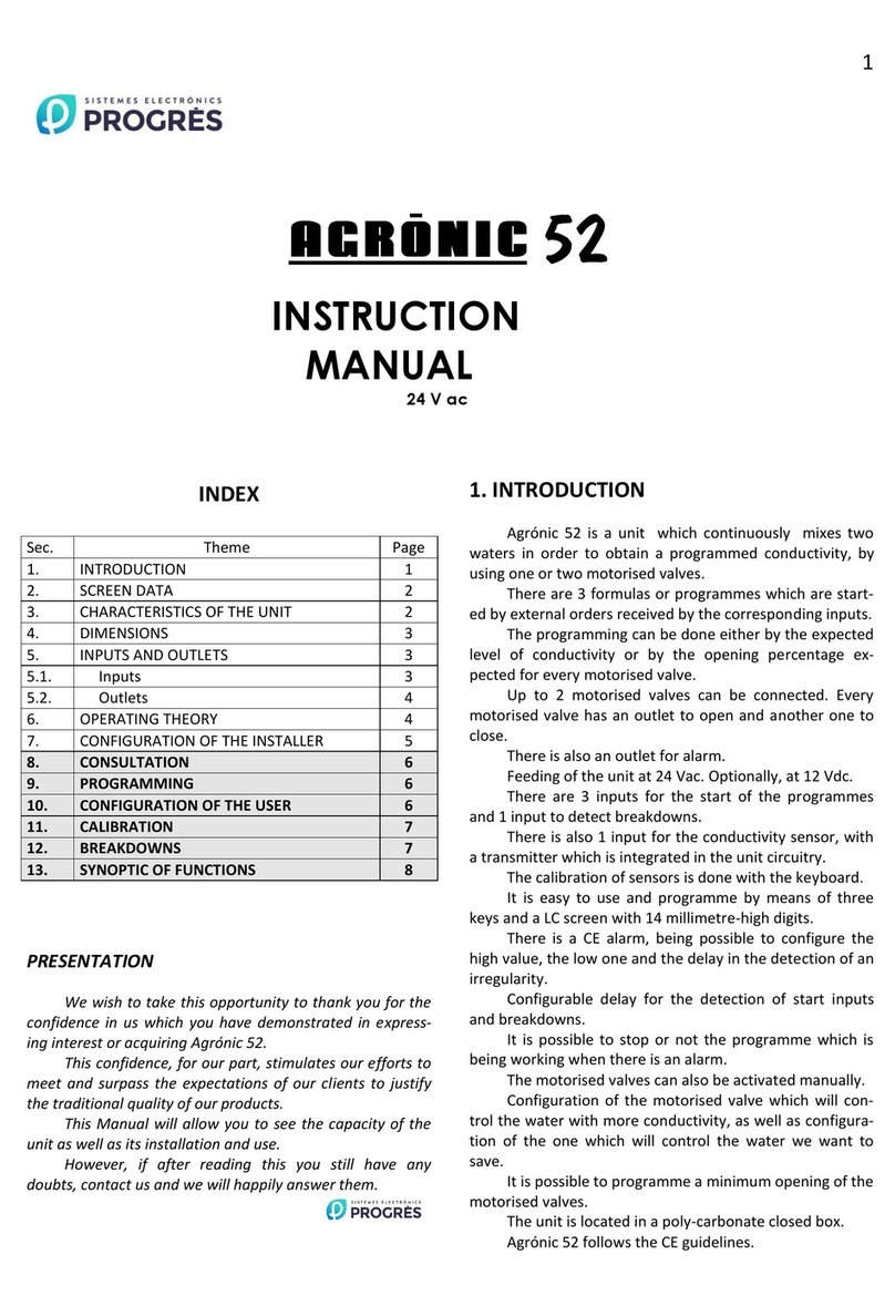
06140344 (Radiocontrol 6i-6o 220V Omnidirectional Antenna 169 MHz)
06140347 (Radiocontrol 6i-6o 220V Auxiliary Master Omnidirectional Antenna 169 MHz)
06140348 (Radiocontrol 6i-6o 12 V Omnidirectional Antenna 169 MHz)
06140349 (Radiocontrol 6i-6o DIN Rail Mounting Omnidirectional Antenna 169 MHz)

2· User Manual | Radiocontrol 6i-6o
This system is based on master-slave operation regardless of the number of modules.
The system can be configured from the factory to operate in two dierent modes:
• Standard mode: has a minimum of two modules and a maximum of seven modules.
Now, in all cases, there will only be one master and the rest of the modules will be slaves
(maximum, six slaves). The input/output mapping between master and slaves is deter-
mined in the factory.
MASTER
SLAVE 1 SLAVE 6

User Manual | Radiocontrol 6i-6o · 3
• Multi-master mode: it has a minimum of two modules and a maximum of eight modules.
In this configuration, there can be up to four masters (one master + three slaves) and four
slaves. In practice, it is as if there were up to four simple master/slave pairs: although in
this case, the four masters use a single antenna and are interconnected via cable (RS485).
In this way, the operation is much more optimal at the radio-electric level, since the entire
system works using a single frequency.
There is also an indication in each module: correct operation, transmission and power connec-
tion.
The radio control is mounted on a DIN rail in an IP65 box.
MASTER 1
RS-485 link
MASTER 4
SLAVE 1 SLAVE 4
A A
B B

4· User Manual | Radiocontrol 6i-6o
Technical specifications
Power supply 220 Vca 12 Vdc
Communication
Temperature 0°C to +45°C
Humidity < 85%
Altitude 2000 m
Pollution Grade II
Environment
Weight 1’2 kg.
High 200 mm
Width 200 mm
Depth 120 mm
Weight and dimensions
Consumption
(in mA)
Master In standby 28 40
Communicating (1 sec.) 70 100
Slave In standby 28 40
Communicating (1 sec.) 70 100
Output power 500 mW
Frequency range 169.4000 - 169-8125 MHz
Channels 16
Channel spacing 25 kHz
Maximum communication distance (according to orography)
Omnidirectional antenna Between 2 and 7 km
This symbol indicates that electronic devices should not be disposed of along with household
waste at the end of its useful life. The product must be taken to the corresponding collection point
for electronic equipment recycling and correctly processed pursuant to Spanish legislation.

User Manual | Radiocontrol 6i-6o · 5
The system can operate in standard mode or multi-master mode. The operating mode and
mapping of the inputs/outputs of the dierent modules in the system must be detailed when
placing the order, as it is configured in the factory.
The master device (or multimaster) will attempt to establish contact with the slave modules
from its connection to the network. To do this, it will be sending interrogation frames until it
receives a response from all the slaves. This interrogation will be:
Once the automatic link between the master module and the slaves has been made, the master
will send a refresh frame according to the set time interval of 1 second. Also, and immediate-
ly when there is a change in the inputs of the master module, its status to each of the slave
modules and each of these will reproduce it on their outputs. Each slave module replies to each
frame received from the master module with the status of its inputs and is reproduced on the
outputs of the master module according to the established input/output mapping.
There can be two security settings in case of radio communication interruption:
• Secure mode: (mode set by default), if the radio communication is interrupted, the
remote relays go to inactive status (open). It is determined that the communication has
been interrupted when 90" have passed without information exchange between master(s)
and slaves.
• Persistent mode: the relays will not change their status if a radio link is cut.
The master(s) is the element of the system that is responsible for supervising the system, pe-
riodically interrogating the slaves. If communication is interrupted, the contact on the output
marked as ALARM will open. The contact remains closed when the communication is correct.
On the slave, this output has no functionality.
Operation
Multimaster mode
1 master Every 1 second
2 masters Every 2 seconds
3 masters Every 3 seconds
4 masters Every 4 seconds
Same
mode
Standard mode
Every 1 second

6· User Manual | Radiocontrol 6i-6o
When starting up each one of the modules, the STATUS LED on the front of each module will
flash for a few seconds with a short but constant flash, indicating that other elements (masters,
slaves) are being searched within the network. With the connection already established, the LED
will flash by emitting groups of flashes, the number of which will depend on the power of the
received signal. This number of flashes can vary between two and seven:
• Two flashes: correspond to the minimum usable power.
• Seven flashes: correspond to the maximum signal available.
If the radio connection is interrupted, the flashes will return to constant short flashes.
Each module has three additional status LEDs at the bottom:
• Yellow LED: Steady indicates communication is established
• Green LED: It will turn on whenever there is an active input
• Red LED: It will turn on whenever there is an active output
LEDs
Inputs: The inputs are located at the bottom of the module and are numbered D1 to D6. To
activate a specific input, it must go to a high logic state: the inputs are active and there must be
a voltage level (5 - 30 V) on the + pin of the corresponding input. The pin immediately to the right
of each input (shown as -) must be connected to earth.
When an input is activated, the corresponding relay in the reciprocal module is activated. The
green LED on the module where the input is activated and the red LED on the module where the
output is activated will also be activated.
Inputs, outputs and antenna

User Manual | Radiocontrol 6i-6o · 7
Master
5-30 Vdc
5-30 Vdc
Power supply
Outputs
Outputs
Inputs
Inputs
Slave
Outputs: The outputs are located at the top and are numbered R1 to R6. Each output is
assigned two terminal points that correspond to the normally open contact of its associated
relay. The maximum load that can be supported by each of the relays is 5 A at 220 Vac.
When an output has been activated, the module's red LED is activated.
To facilitate the passage of the hose from the inputs and outputs of each module to the devices
to be activated, three cable glands have been placed in the boxes.
Antenna: The standard system is served with omnidirectional antennas and their respective
cables, 10 metres long, to connect to the modules. The module output consists of an SMA-type
female connector, where the 10-metre cable is connected, which is finished with an N connector
at the other end, where the antenna is connected.
Power supply: Each of the modules is delivered with a 220 Vac 12 Vdc, 2A transformer, in
the case of modules powered at 220 Vac.
Power supply

R-2374
Polígon Industrial, C/ de la Coma, 2 | 25243 El Palau d’Anglesola | Lleida | España
Tel. 973 32 04 29 | info@progres.es | www.progres.es
Sistemes Electrònics Progrés, S.A.
The drawings show a practical example of an installation that is irrigated with water from a
reservoir filled with a re-pump located in a river.
This is a "standard mode" installation (master-slave radio control) where a digital sensor is
connected to the radio control located in the reservoir which, when insuicient water is detected
(contact closes), sends an order to the radio control located in the river to start the pump and
fill the reservoir.
Other practical examples:
• Control from the Agrónic 2500 of one or several pivots to remotely control, in each of them,
their own manoeuvres such as activation, speed, le-right movement, forward, etc.
• Remote control for starting submerged pumps in wells.
Graphic installation example
A B
B
A
Digital sensor
This manual suits for next models
4
Table of contents
Other Progres Controllers manuals
