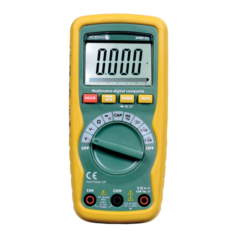
Projecta DT150 User manual

TRUE RMS MULTIMETER
P/No. DT150

IMPORTANT SAFETY INFORMATION
Please read this manual thoroughly before use and store in a safe place for future reference
WARNING
• The meter’s safety features may not protect the user if not used in accordance with the
manufacturer’s instructions.
• Keepngersawayfromthemetalprobetipswhentakingmeasurements.
• Before changing functions using the selector switch, always disconnect the test leads
from the circuit under test.
• Comply with all applicable safety codes. Use approved personal protective equipment
whenworkingnearliveelectricalcircuits.
• Usecautiononlivecircuits.Voltagesabove30VACrms,42VACpeak
or60VDCposeashockhazard.
• Verifyoperationbeforeusingmeterbymeasuringaknownlivevoltage.
• Measurements in the 10A range should be limited to 30 seconds maximum every 15 minutes.
• Never test resistance, diodes, or continuity on a live circuit.
• Toavoidelectricshock,disconnectpowertotheunitundertestanddischargeallcapacitorsbefore
takinganycapacitancemeasurements.Removethebatteriesandunplugthelinecords.
• RiskofElectrocution.Beforeuse,alwaystesttheVoltageDetectoronaknownlivecircuittoverify
proper operation.
• Do not touch the temperature probe to live circuits.
• Do not use the meter if the meter or test leads appear damaged.
• Do not use the meter in wet or damp environments or during electrical storms.
• Do not use the meter or near explosive vapours, dust, or gasses.
• Do not use the meter if it operates incorrectly, protection may be compromised.
• Do not use the meter while Low Battery warning is on, replace batteries immediately.
• Do not apply voltage or current that exceeds the meter’s maximum rated input limits.
• Do not measure voltages if a motor or the circuit is being switched ON or OFF. Large voltages surges
may occur that can damage the meter.

FUNCTIONS
TRUE RMS
Provides a more accurate measure of AC signals that are imperfect waveforms
MULTI-TEST
Test everything from voltage and frequency, resistance, and continuity along with the ability to test diodes
and temperature
NON-CONTACT VOLTAGE DETECTION
Safely measure AC live voltage without even touching the circuit
LCD DISPLAY
An illuminated digital LCD display will ensure clear and precise data
PRODUCT OVERVIEW
1. LCD Display
2. Non-Contact Voltage Indicator
3. MODE/RELATIVEButton
4. RANGEButton
5. MAX/MIN Button
6. HOLD/BacklightButton
7. Function Switch
8. 10AInputJack
9. COMInputJack
10.PositiveInputJack
11.Non-Contact Voltage Detector
12.Lanyard Hole
13.Test Lead Holders
14.BatteryCoverLock
15.Tilt Stand
16.Battery Cover
SYMBOLS USED ON LCD DISPLAY
1. Auto Power Off
2. AutoRanging
3. Maximum
4. Minimum
5. Display Hold
6. Diode Test
7. Continuity
8.RelativeMode
9. Degree Celsius/Degree Fahrenheit
10. Units of Measure List
11. MeasurementReading
12. Low Battey
13. Minus Sign
14. Direct Current
15. Alternating Current

BUTTON FUNCTIONS
MODE AND REL (RELATIVE) BUTTON
• PresstheMODEbuttontoselectAC/DCVoltage,AC/DCCurrent,Frequency,Ohms,DiodeTest,
Continuity or Capacitance, Temperature.
• PresstheRELbuttonfor>2secondstoturnonorofftheRelativefunction.
• TheRelativefunctionzerosoutthereadingdifferencebetweentheactualmeasurementandthestore
reference value.
NOTE:RELdoesnotworkonFrequency,DiodeTest,Continuity
RANGE BUTTON
• Whenthemeterisrstturnedon,itautomaticallygoesintoAutoRanging.
• This automatically selects the best range for the measurements being made and is generally the best
mode for most measurements.
• Formeasurementsituationsrequiringthatarangebemanuallyselected,performthefollowing:
1. PresstheRANGEbutton,the“AUTO”displayindicatorwillturnoff.
2. PresstheRANGEbuttontocyclethroughtherangesuntilyouselecttherangeyouwant.
3. PressandholdtheRANGEbuttonfor2secondstoexittheManualRangingmodeand
returnAutoRanging.
MAX/MIN BUTTON
1. MomentarilypresstheMAX/MINbuttontoactivatetheMAX/MINmode,the“MAX”indicatorwill
appear on the LCD display, the meter will display and hold the maximum reading and will update
whenahigher“max”occurs.
2. MomentarilypresstheMAX/MINbuttonagaintoviewthelowerreading,“MIN”indicatorwillappear
on the LCD display, the meter will display and hold the maximum reading and will update when a
lower“min”occurs.
3. Press and hold the MAX/MIN button to end MAX/MIN and return to normal operation.
NOTE:ThemeterdoesnotautorangewhentheMAX/MINmodeisactive,thedisplaywillread‘OL’ifthe
rangeexceeded.Whenthisoccurs,exitMAX/MINandusetheRANGEbuttontoselectahighrange.MAX/
MINdoesnotworkonFrequency,DutyCycle,DiodeTest,ContinuityandCapacitance.
HOLD/BACKLIGHT BUTTON
• PresstheHOLD/BacklightbuttontoturnonorofftheHOLDfunction.
• PresstheHOLD/Backlightbuttonfor>2secondstoturnonorofftheBacklightfunction.
AUTO POWER OFF
• The auto off feature will turn the meter off after 15 minutes.
• Todisabletheautopowerofffeature,holddowntheMODEbuttonandturnthemeteron.
LOW BATTERY INDICATION
• The“ ”iconwillappearinthelowerleftcornerofthedisplaywhenthebatteryvoltage
becomes low.
• Replacethebatterywhenthisappears.

AC/DC VOLTAGE (FREQUENCY) MEASUREMENT
1. Set the rotary function switch to the V AC/DC position.
2. ToselectACorDCvoltage,presstheMODEbuttonuntiltheAC or DC symbol appears
on the LCD display.
3. InserttheblacktestleadbananaplugintothenegativeCOMInputJack;Inserttheredtestlead
bananaplugintothePositiveInputJack.
4. Touchtheblacktestprobetiptothenegativesideofthecircuit;Touchtheredtestprobetip
to the positive side of the circuit.
5. ReadthevoltageontheLCDdisplay.
6. PresstheMODEButtontoindicateHz.
7. Readthefrequencyinthedisplay.
FREQUENCY (ELECTRONIC) MEASUREMENT
1. SettherotatoryfunctionswitchtotheHzposition.
2. InserttheblacktestleadbananaplugintothenegativeCOMInputJack;Inserttheredtestlead
bananaplugintothePositiveInputJack.
3. Touch the test probe tips to the circuit under test.
4. Readthefrequencyinthedisplay.

AC/DC CURRENT MEASUREMENT
1. InserttheblacktestleadbananaplugintotheCOMInputJack.
2. For current measurements up to 10A AC/DC, set the rotary function switch to the 10A position and
inserttheredtestleadintothe10AInputJack.
3. For current measurements up to 400mA AC/DC, set the rotary function switch to the mA position and
inserttheredtestleadintothePositiveInputJack.
4. For current measurements up to 4000µA AC/DC, set the rotary function switch to the µA position and
inserttheredtestleadintothePositiveInputJack.
5. ToselectACorDCcurrent,presstheMODEbuttonuntiltheAC or DC symbol appears
on the LCD display.
6. Removepowerfromthecircuitundertest,thenopenupthecircuitatthepointwhereyouwishto
measure current.
7. Touchtheblacktestprobetiptotheneutralsideofthecircuit;Touchtheredtestprobetiptothe
“hot”sideofthecircuit.
8. Apply power to the circuit.
9. Readthecurrentinthedisplay.
RESISTANCE MEASUREMENT
1. Set the rotary function switch to the CAP position.
2. PresstheMODEbuttonuntiltheΩsymbolappearsontheLCDdisplay.
3. InserttheblacktestleadbananaplugintothenegativeCOMInputJack;Inserttheredtestleadinto
thePositiveInputJack.
4. Touch the test lead probes to the component under test, if the component is installed in a circuit, it is
best to disconnect one side before testing to eliminate interference with other devices.
5. Readtheresistanceinonthedisplay.

DIODE TEST
1. Set the rotary function switch to the CAP position.
2. PresstheMODEbuttonuntilthesymbolappearsontheLCDdisplay.
3. InserttheblacktestleadbananaplugintothenegativeCOMInputJack;Inserttheredtestleadinto
thePositiveInputJack.
4. Touch the test lead probes to the diode under test.
5. Forwardvoltagewillindicate0.4to0.7VontheLCDdisplay;Reversevoltagewillindicate“OL”;
Shorteddeviceswillindicatenear0andanopendevicewillindicate“OL”inbothpolarities.
CONTINUITY CHECK
1. Set the rotary function switch to the CAP position.
2. PresstheMODEbuttonuntilthe symbol appears on the LCD display.
3. InserttheblacktestleadbananaplugintothenegativeCOMInputJack;Inserttheredtestleadinto
thePositiveInputJack.
4. Touch the test lead probes to the device or wire under test.
5. A beeper will sound if the resistance is approximately 50ohms or less and the resistance reading will
be shown on the display.

CAPACITANCE MEASUREMENT
1. Set the rotatory function switch to the CAP position.
2. PresstheMODEbuttonuntilthe“nF”symbolappearsontheLCDdisplay.
3. InserttheblacktestleadbananaplugintothenegativeCOMInputJack;Inserttheredtestleadinto
thePositiveInputJack.
4. Touch the test leads to the capacitor to be tested, wait until the readings settle before ending the test.
5. Readthecapacitancevalueinthedisplay.
TEMPERATURE MEASUREMENT
1. Set the function switch to the Temp position.
2. PresstheMODEbuttonuntiltheoCoroF.
3. Connectthetemperatureprobetothebananaplugadapter,notethe–and+markingsontheadapter.
4. Connecttheadaptertothemeter,makingsurethe–sidegoesintotheCOMInputJackandthe+side
goesintothePositiveInputJack.
5. Touch the tip of the temperature probe to the object being measured.
6. Readthetemperatureinthedisplay.

NON-CONTACT AC VOLTAGE DETECTION
1. Set the rotary function switch to the NCV position.
2. Hold the detector close to the AC voltage being tested.
3. Ifnosignalisdetected,theLCDwillshow“EF”,NCVindicatorlightwillnotashandthebuzzerwill
not sound.
4. Accordingtothedetectedsignalstrength,LCDdisplaysdifferenthorizontallines.
•Whenthesignalisstrongest,fourhorizontallineswithappearontheLCDdisplay.
•Whenthesignalisweakest,onlyonelinehorizontallinewillappear.
•Meanwhile,NCVindicatorlightashesandthebuzzermakeadifferentsound.
NOTE:Thesensinglevelvarieswiththedistancebetweenthesensingpartandthe
measured AC power cord.
NOTE:Thedetectorisdesignedwithhighsensitivity.Staticelectricityorothersourcesofenergymay
randomly trip the sensor. This is normal operation.
REPLACING THE BATTERY
1. Makesuretodisconnectthetestleadsfromanysourceofvoltagebeforeremovingbatterycover.
2. Counterrotate180degreestoopenthebackcoverofbattery.
3. ReplaceoldbatterieswithtwoAAA1.5Vbatteries.
4. Reassemblethemeter.
REPLACING THE FUSES
1. Disconnect the test leads from the meter.
2. Counterrotate180degreestoopenthebackcoverofbatteryforthe500mA/600Vfastandremovethe
rear cover for the 10A/600V fast.
3. Gentlyremovetheoldfuseandinstallthenewfuseintotheholder.
4. Alwaysuseafuseofthepropersizeandvalue(500mA/600VfastblowfortheµA/mArangeor
10A/600V fast blow for the 10A range).
5. Replaceandsecuretherearcover.

GENERAL SPECIFICATIONS
Insulation Class 2, Double Insulation
Diode Test Test current approx.1 mA , open circuit voltage of 2V typical
Continuity Test Audiblesignaliftheresistanceis<50Ω
Low Battery Indication “”isdisplayed
Display 4000 count LCD
OverRangeIndication "OL'' is displayed
Polarity Minus symbol"-" is displayed for negative polarity
MeasurementRate 3 readings per second, nominal
Auto Power Off approx. 15 minutes
Input Impedance >10MΩACandDCVoltage
ACResponse TrueRMS
AC Voltage Bandwidth 50Hzto1kHz
AC Current Bandwidth 50Hzto400Hz
Batteries Two AAA 1.5V batteries
Fuse 10A/600VfastactingFuse;500mA/600VfastactingFuse
OperatingEnvironment 5 to 40°C [41 to 104° FJ
StorageEnvironment -10 to 50°C [14 to 122° Fl
Operating Humidity Max 80% up to 31 °C [87°F] decreasing linearly to 50% at 40°C
[104°F]
Storage Humidity <80%
Dimensions/Weight 154x7 4x43mm / Approx. 21 Og [No batteries]
Safety Complies with UL 61010-1 v.3 for measurement Category
III600V, Pollution Degree 2.
ELECTRICAL SPECIFICATIONS
FUNCTION RANGE RESOLUTION ACCURACY
ACTrueRMSVoltage
4.000V 0.001V ±(1.2%+3digits)
40.00V 0.01V
400.0V 0.1V ±(1.2%+5digits)
600V 1V
AllACvoltagerangesarespeciedfrom5%ofrangeto100%ofrange.
ACVoltageBandwidth:50Hzto60Hz(Allwave);50Hzto1kHz(Sinewave).
DC Voltage
400.00mV 0.1mV
±(0.5%+8digits)
4.000V 0.001V
40.00V 0.01V
400.0V 0.1V
600V 1V
AC True RMS Current
400.0µA 0.1µA
±(1.0%+5digits)4000µA 1µA
40.00mA 0.01mA
400.0mA 0.1mA ±(1.2%+8digits)
4.000A 0.001A ±(2.0%+3digits)
10.00A 0.01A ±(2.0%+5digits)
AllACcurrentrangesarespeciedfrom5%ofrangeto100%ofrange.
ACCurrentBandwidth:50Hzto60Hz(Allwave);50Hzto400Hz(Sinewave).

FUNCTION RANGE RESOLUTION ACCURACY
DC Current
400.0µA 0.1µA
±(1.0%+5digits)4000µA 1µA
40.00mA 0.01mA
400.0mA 0.1mA ±(1.0%+8digits)
4.000A 0.001A ±(2.0%+3digits)
10.00A 0.01A ±(2.0%+5digits)
Temperature -18 to 1000oC 1oC ±(1.5%+5oC)
0 to 1832oF 1oF ±(1.5%+9oF)
Resistance
400.0Ω 0.1Ω
±(1.2%+5digits)
4.000kΩ 0.001kΩ
40.00kΩ 0.01kΩ
400.0kΩ 0.1kΩ
4.000MΩ 0.001MΩ ±(2.5%+8digits)
40.00MΩ 0.01MΩ ±(3.0%+8digits)
Capacitance
4.000nF 0.001nF ±(3.5%+60digits)
40.00nF 0.01nF ±(3.5%+10digits)
400.0nF 0.1nF
4.000µF 0.001µF ±(4.0%+5digits)
40.00µF 0.01µF
400.0µF 0.1µF ±(3.5%+5digits)
4.000mF 0.001mF
FUNCTION RANGE RESOLUTION ACCURACY
Frequency (Electrical)
4.000Hz 0.001Hz
±(1.2%+5digits)
40.00Hz 0.01Hz
400.0Hz 0.1Hz
4.000kHz 0.001kHz
10.00kHz 0.01kHz
Sensitivity: >15V RMS
Frequency (Electronic)
2.000Hz~4.000Hz 0.001Hz
±(1.2%+5digits)
40.00Hz 0.01Hz
400.0Hz 0.1Hz
4.000kHz 0.001kHz
40.00kHz 0.01kHz
400.0kHz 0.1kHz
4.000MHz 0.001MHz
10.00MHz 0.01MHz
>0.8VRMSwhile100kHz;3VRMSwhile>100kHz
Note:Accuracyisstatedat18to28°C[65to83°F)andlessthan75%RH.
Note:Accuracyspecicationsconsistoftwoelements:
• [% reading)-This is the accuracy of the measurement circuit.
• [+ digits)-This is the accuracy of the analog to digital converter.

WARRANTY STATEMENT
Brown&WatsonInternationalPtyLtd(“BWI”)of1500FerntreeGullyRoad,Knoxeld,Vic.,telephone(03)
97306000,fax(03)97306050,warrantsthatallproductsdescribedinitscurrentcataloguewillunder
normaluseandservicebefreeoffailuresinmaterialandworkmanshipforaperiodofthree(3)years
fromthedateoftheoriginalpurchasebythecustomerasmarkedontheinvoice.Thiswarrantydoesnot
cover ordinary wear and tear, abuse, alteration of products or damage caused by the purchaser.
Tomakeawarrantyclaimtheconsumermustdelivertheproductattheircosttotheoriginalplaceof
purchase or to any other place which may be nominated by either BWI or the retailer from where the
product was bought in order that the warranty assessment may be performed. The consumer must also
deliver the original invoice evidencing the date and place of purchase together with an explanation in
writing as to the nature of the claim. In the event that the claim is determined to be for a minor failure of
the product then BWI reserves the right to repair or replace it at its discretion. In the event that a major
failure is determined the consumer will be entitled to a replacement or a refund as well as compensation
for any other reasonably foreseeable loss or damage.
This warranty is in addition to any other rights or remedies that the consumer may have
under State or Federal legislation.
IMPORTANT NOTE
Our goods come with guarantees that cannot be excluded under the Australian Consumer
Law. You are entitled to a replacement or refund for a major failure and compensation for
any other reasonably foreseeable loss or damage. You are also entitled to have the goods
repaired or replaced if the goods fail to be of acceptable quality and the failure does not
amount to a major failure.
Distributed by
AUSTRALIA
Brown & Watson International Pty. Ltd.
KnoxeldVictoria3180
Phone:(03)97306000
Fax:(03)97306050
NationalTollFree:1800113443
NEW ZEALAND OFFICE
Grifths Equipment Ltd.
19 Bell Avenue,
Mount Wellington,
Auckland1060,NewZealand
Phone:(09)5254575
Fax:(09)5791192
IS506
Issue 1 17/11/22
Table of contents
Other Projecta Multimeter manuals
