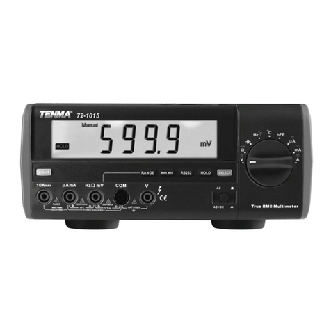
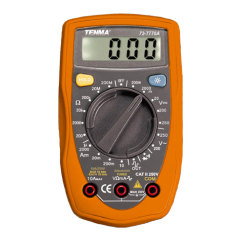
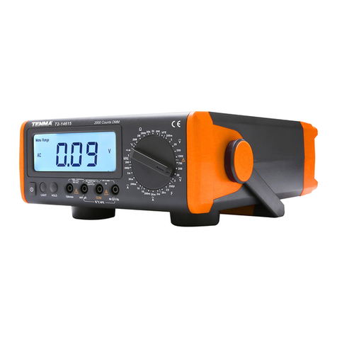
Tenma 72-8720 User manual

1
Model: 72-8720
Digital Bench Multimeter

2
Please read these instructions carefully before use and retain for future
reference.
• This meter is designed to meet IEC61010-1, 61010-2-032, and 61010-2-033 in
Pollution Degree 2, Measurement Category (CAT I 1000V, CAT II 600V, CAT III
300V) and double Insulation.
• When using electrical appliances basic safety precautions should always be
followed.
• Please operate according to this manual, otherwise the protection provided by the
device will be impaired or fail.
• There are no user-serviceable parts in this product. Refer servicing to qualied
personnel.
• Use only the test leads supplied or the protection may be impaired.
• Check the test leads, probe and case insulation condition before using. If you nd
any breakage, damage or abnormality, or you consider the device is broken, stop
using the device immediately.
• When using the test probes, keep your ngers behind the nger protection rings.
• Ensure all inputs are less than the range selected otherwise it may cause electrical
shock or meter damage.
• Take caution when voltages are above 60V DC and 30V AC rms.
• Do not use the meter with the battery or fuse covers removed.
• Do not adjust the range selector during measurement.
• Replace the batteries as soon as the low battery indicator appears on the display.
• Remove dead batteries from the meter or if it is not going to be used for a long
time.
• Never mix old and new batteries together, or different types of batteries.
• Never dispose of batteries in a re, or attempt to recharge ordinary batteries.
• Before replacing the battery, turn off the meter and disconnect all the test probes
• To prolong battery life turn off the meter after use.
ELECTRICAL SYMBOLS GUIDE
WHAT’S INCLUDED
• Bench type digital multimeter.
• Installation guide and computer interface software (CD-ROM).
• Operating manual.
• Power cord.
• Alligator clip.
• Multi purpose socket.
• Temperature probe.
• Test leads (1 pair).
• RS232 interface cable.
• USB interface cable.
IMPORTANT SAFETY INFORMATION
AC or DC Ground Double insulated
Continuity test
Low batteryWarning
Capacitance test
Diode test Fuse
}Stored in compartment in the back of the unit.

3
FUNCTIONS
Function buttons Operation performed
SELECT SELECT: used to select any rotary switch alternate function
LIGHT LIGHT: under battery power turns backlight on
RANGE Exit AUTO and enter MANUAL ranging. In MANUAL select next
input range. Press EXIT to return to AUTO (default)
STORE Stores the current measurement value. Press EXIT to return
RECALL Recall the stored value. Press EXIT to return
SETUP Access setup selections. Display ‘SET’ is ashing. Each press
moves to the next selection.
SEND Press to output data, AUTO mode off. Press EXIT to quit
In SETUP press to select OFF at selection of HIGH and LOW
MAXMIN
Displays max/min and current reading. Press exit to quit
In SETUP each press select next digit
In RECALL press to enable SEND feature
In STORE press to switch between clearing or start storing
reading from current index number
REL
Enter RELATIVE mode. Upper right secondary display shows
present value. Lower right secondary display shows stored
value. Primary display shows present measurement minus
stored value. Press EXIT to quit mode.
Range Selector
Positions
Rotary Switch Function Blue SELECT Function
V
DC voltage measurement None
~
V
AC voltage measurement None
Hz Duty
mV
DC millivolt measurement Frequency measurements
Duty Cycle measurement
Resistance measurement Diode test
Continuity test
Capacitance test None
ºC ºF Centigrade temp measurement Fahrenheit temp measurement
μA
AC or DC current
measurement (40ma, 400ma)
Switch between AC or DC
mA %
AC or DC current
measurement (40ma, 400ma)
Switch between AC or DC
4-20mA loop as % reading
AAC or DC current
measurement (10A)
Switch between AC or DC
Ω

4
Function buttons Operation performed
REL
In SETUP each press decrements an option
In RECALL each press goes back to previous reading
In STORE each press decreases a second on the storing
interval. Press EXIT to exit.
HOLD HOLD freezes the displayed value. Press EXIT to release.
PEAK Press to access Peak Hold feature. Primary display shows peak
hold reading. Press EXIT to quit.
EXIT Press to exit certain button functions.
AC/DC In AC measurement mode press to display AC+DC True RMS
value and AC+DC.
OPERATING PARAMETERS
FRONT PANEL LAYOUT
• Ambient temperature : 0ºC ~ 40ºC.
• Relative humidity : ≤75% @ 0ºC ~ 30ºC, ≤50% @ 31ºC ~ 40ºC
• Maximum operating altitude 2000m
• Maximum Display : Digital: 5999
• Measurement Speed : Updates 2-3 times/second
• Polarity display : Automatic
• Turn the Range Selector to power the meter on and select a function. The display
initially shows a standard setup for that function.
• Use the blue SELECT button to choose an alternate function for the chosen
setting.
• Changing the main setting does not carry over the alternative function setting.
LCD Display
Function Buttons
Range Selector
Select Button
Input Terminals AC/AC+DC Button
SELECT RANGE STORE RECALL SETUP

5
Function Primary Display Lower right
Secondary Display
Upper right Secondary
Display
DCV Tested DC Voltage value No Display Full range: 4,40,400,1000
ACV Tested AC Voltage value
Tested frequency
value: 40kHz ~
250kHz
Full range: 4,40,400,750
DCmV Tested DCmV value No display Full range: 400
Ω
Tested resistance value No display Full range: 400, 4, 40, 400,
4, 40
Tested resistance value No display Full range value: 400
Tested resistance value No display Full range: 4
Hz Tested frequency value No display Full range: 40, 400, 4, 40,
400, 4, 40, 400
Tested capacitance value No display Full range: 40, 400, 4, 40,
400, 4, 40
ºC Tested ºC value No display 1000
ºF Tested ºF value No display 1832
DC
μA
Tested DC
μA value
N/A Full range: 400, 4000
AC
μA
Tested AC
μA value
Tested frequency
value 40kHz ~ 100kHz Full range: 400, 4000
DCmA Tested DCmA value No display Full range: 40, 400
ACmA Tested ACmA value Tested frequency
value 40kHz ~ 100kHz Full range: 400, 4000
DCA Tested DC current value No display Full range: 10
ACA Tested AC current value Tested frequency
value 40kHz ~ 100kHz Full range: 10
STORE Current measurement
reading
Value of the
corresponding index
number
Index number increase one.
Index number:
no.0001~9999
RECALL The recalled value The total number of
stored value
Index number:
no.0001~9999
Max/min Current measurement
reading
Minimum reading
value Maximum reading value
REL Present measurement
value minus stored value The stored value Present measurement value

6
Symbol Meaning
MAX Maximum reading displayed
MIN Minimum reading displayed
No The sequence of reading
ºC, ºF Degrees celcius (default) or fahrenheit
H
μmS
H: hour
μ: micro
m: minutes
S: seconds
- Negative reading
Low battery - replace as soon as possible to avoid inaccurate
readings.
SET Setup feature is enabled
AC+DC
For DCV and DCA functions, reading represents trueRMS total of AC
and DC measurements
True RMS Indicator for true RMS value
Ω, kΩ, mΩ
Ohm unit of resistance
Kiloohm 2x10
3
or 1000ohms
Megaohm 1x10
6
or 1,000,000ohms
Hz, kHz
MHz
Hertz unit of frequency measurement
Kilohertz
1x10
3
or 1000hertz
Megahertz
1x10
6
or 1,000,000hertz
V, mV Volts unit of measurement
Millivolt 1x10⁻³ or 0.001volts
μA, mA, A
Amperes unit of current
Milliamp 1x10⁻³ or 0.001amperes
Microamp 1x10
-6
or 0.000001amperes
F, mF
μF, nF
Farad unit of measurement
Nanofarad. 1x10
-9
or 0.000000001 farads
Microfarad.1x10-6 or 0.000001 farads
Millifarad. 1x10⁻³ or 0.001 farads
Automatic power off feature is turned on
Continuity test sounder
STO Data store is on
RCL Data recall is on
∆Relative mode displays present value minus stored value.
• Auto ranging (AUTO in the display) always comes on initially when you select a
new function. In auto range, the Meter selects the lowest input range possible,
ensuring that the reading appears with the highest available resolution.
• Press RANGE to enter MANUAL ranging in the present setting. You can then
select the next manual range higher by repeatedly pressing RANGE. Return to
auto ranging by pressing EXIT.
• Press RANGE when turning on the Meter, the Meter enters the analogue
resistance signal measurement mode.

7
OPERATION
DC Voltage Measurement
Warning: To avoid personal injury, or damage to the meter from electric shock, please
do not attempt to measure voltages higher than 1000V although readings may be
obtained.
To measure DC voltage, connect the meter as follows:
• Insert the red test lead into the V terminal and the black test lead into the COM
terminal.
• Set the rotary switch to .
• Connect the test leads across with the object being measured. The measured DC
voltage’s true RMS value shows on the display.
• When measurement has been completed, disconnect the connection between the
test leads and the circuit under test.
Note: In each range, the meter has an input impedance of 10M
Ω
except 600mV range
has 3000M
Ω
. This loading effect can cause measurement errors in high impedance
circuits. If the circuit impedance is less than or equal to 10k
Ω
, the error is negligible
(0.1% or less).
Symbol Meaning
LOW Indicates lowest setup limit
AUTO The meter is set to auto range with range for best resolution selected
SEND Data output in progress
Backlight feature is on
HOLD Data hold mode is active
PEAK HOLD Peak hold mode is active
Diode test
% Frequency signal duty cycle. 4~20mA loop current as % reading
>OL
Input value overload for the selected range
Analogue Bar Provides an analogue bar graph of the present input, quick response
Analogue Bar Graph
The bar graph provides an analogue indication of the measured input. For most
measurement functions, the bar graph updates 10 times per second.

8
AC Voltage Measurement
Warning: To avoid personal injury, or damage to the meter from electric shock, please
do not attempt to measure voltages higher than 1000V although readings may be
obtained.
To measure AC voltage, connect the meter as follows:
• Insert the red test lead into the V terminal and the black test lead into the COM
terminal.
• Set the rotary switch to ~.
• Connect the test leads across with the object being measured. The measured AC
voltage’s true RMS value shows on the display.
• When a ACV function is selected, you can press the AC+DC button to view the AC
+ DC True RMS value in the primary display.
• When measurement has been completed, disconnect the connection between the
test leads and the circuit under test.
Note: In each range, the meter has an input impedance of 10M
Ω
except 600mV range
has 3000M
Ω
. This loading effect can cause measurement errors in high impedance
circuits. If the circuit impedance is less than or equal to 10k
Ω
, the error is negligible
(0.1% or less).
DC Millivoltage Measurement
Warning: To avoid damage to the meter, please do not attempt to measure voltages
higher than 400mV although readings may be obtained.
To measure DC Millivoltage, connect the meter as follows:
• Insert the red test lead into the V terminal and the black test lead into the COM
terminal.
• Set the rotary switch to mV . Press the SELECT button to cycle through
frequency and duty cycle.
• Connect the test leads across with the object being measured. The measured
RMS value shows on the display.
• When measurement has been completed, disconnect the connection between the
test leads and the circuit under test.
•
•
Note: When measuring DC Millivoltage, the Meter acts around a 2.5G
Ω
input
impedance in parallel with the circuit.

9
DC or AC Current Measurement
Warning: Before connecting the meter in series with the circuit under test, be sure
power the circuit is off. If the fuse burns out during measurement, the meter may be
damaged and there is risk of personal injury to the operator.
Use correct terminals, function, and range for the measurement. When the test leads
are connected to the current terminals, do not connect in parallel across any circuit.
To measure current, do the following:
• Insert the red test lead into the μA mA terminal and the black test lead into the
COM terminal.
• Set the rotary switch to an appropriate measurement position in μA , mA or
A , press SELECT button to select AC measurement mode. Default is DC.
• Connect the test leads in series with the object being measured. The measured
value shows on the display.
• The measurement displays True RMS value.
• Press AC/AC+DC button to measure AC+DC current’s true RMS.
Note: If the value of current to be measured is unknown, use the maximum
measurement position, and reduce the range step by step until a satisfactory reading is
obtained.
• Each measurement time of high current (>5A) should be less than 10 seconds and
the interval time between 2 measurements should be greater than 15 minutes.
• When current measurement is complete, disconnect the test leads from the circuit
under test.
Measuring Resistance
Warning: To avoid damage to the meter or to the devices under test, disconnect circuit
power and discharge all the high-voltage capacitors before measuring resistance.
To avoid possible injury, please do not attempt to input voltages higher than 60V DC or
30V AC.
To measure resistance, connect the meter as follows:
• Insert the red test lead into the
Ω
terminal and black lead into the COM terminal.
• Set the rotary switch to
Ω
and press SELECT button to select
Ω
measurement
mode.
• Connect the test leads across with the object being measured. The measured
value shows on the display.

10
Continuity Test
Warning: To avoid damage to the meter or to the devices under test, disconnect circuit
power and discharge all the high-voltage capacitors before testing for continuity.
To avoid personal injury, please do not attempt to input voltages higher than 60V DC or
30V AC.
To test for continuity, connect the meter as below:
• Insert the red test lead into the
Ω
terminal and the black test lead into the COM
terminal.
• Set the rotary switch to
Ω
and press SELECT button to select
measurement mode.
• Connect the test lead across with the object being measured. The buzzer sounds
if the resistance of a circuit under test is <50
Ω
, the circuit is in good condition. The
buzzer does not sound if the resistance of a circuit under test is >50
Ω
, the circuit
is broken.
• The measured value shows on the display and the unit is
Ω
.
Note: In continuity mode, the resistance range is 400
Ω
, and the open circuit voltage is
approximately 1.2V.
• When continuity testing has been completed, disconnect the connection between
the test leads and the circuit under test.
Note: When measuring low resistances, the test leads and internal wiring will add
approximately 0.1 ~ 0.2
Ω
of error. To obtain accurate readings in low-resistance, short-
circuit the test lead beforehand and record the reading obtained, call this reading as
X. Then use the equation: measured resistance value (Y) – (X) = accurate readings of
resistance.
• If reading with shorted test leads is not < 0.5
Ω
, check for loose test leads or
possible incorrect function selection.
• When measuring high resistance (>1M
Ω
), it is normal to take several seconds to
obtain a stable reading.
• The LCD displays OL indicating open-circuit or the resistor value is higher than the
maximum range of the meter.
• When testing the resistance signal from the calibrator, it is necessary to press and
hold the RANGE while turning on the Meter to change the maximum display to
4000 counts but the accuracy remains unchanged.
• When resistance measurement has been completed, disconnect the connection
between the test leads and the circuit under test.

11
Diode Test
Warning: To avoid possible damage to the meter and to the device under test,
disconnect circuit power and discharge all high-voltage capacitors before testing
diodes. To avoid personal injury, please do not attempt to input voltages higher than
60V DC or 30V AC.
• Perform the diode test to check diodes, transistors, and other semiconductor
devices. The diode test sends a current through the semiconductor junction, and
then measures the voltage drop across the junction. A good silicon junction drops
between 0.5V and 0.8V.
To test a diode out of a circuit, connect the meter as follows:
• Insert the red test lead into terminal and the black test lead into the COM terminal.
• Set the rotary switch to
Ω
and press SELECT button to select measurement
mode.
• For forward voltage drop readings on any semiconductor component, place the
red test lead on the component’s anode and place the black test lead on the
component’s cathode. The measured value shows on the display.
• Note Connect the test leads to the proper terminals as said above to avoid error
display. The LCD will display OL indicating diode being tested is open or polarity
is reversed. The unit of diode is Volt (V), displaying the forward voltage drop
readings.
• Open circuit voltage is around 2.7V.
• When diode testing is completed, disconnect the test leads from the device under
test.
Capacitance Measurement
Warning: To avoid damage to the meter or to the equipment under test, disconnect
circuit power and discharge all high-voltage capacitors before measuring
capacitance. Use the DC Voltage function to conrm that the capacitor is discharged.
To measure capacitance, connect the meter as follows:
• Insert the red test lead into the Hz
Ω
mV terminal and the black test lead into the
COM terminal.
• Set the rotary switch to . The Meter may display a xed reading which is a
internal distributed capacitor value. For testing less than 10nF capacitor, the
tested value must subtract the 3. It is recommended to use test clip to carry out
measurement to reduce the effect of internal capacitance.

12
Frequency Measurement
Warning: To avoid the risk of personal injury, do not attempt to measure frequency with
voltage higher than 30V RMS.
To measure frequency, connect the meter as follows:
• Insert the red test lead into the Hz terminal and the black test lead into the COM
terminal.
• Set the rotary switch to Hz%mV and press SELECT button to select Hz
measurement mode.
• Connect the test leads across with the object being measured. The measured
value shows on the display.
• When frequency measurement is complete, disconnect the test leads from the
circuit under test.
Note: When making frequency measurements, the measured signal “a”, must fall
within the following voltage level:
10Hz ~ 1MHz 150mV ≤ a ≤ 30V rms
> 1MHz ~ 10MHz 300mV ≤ a ≤ 30V rms
> 10MHz ~ 50MHz 600mV ≤ a ≤ 30V rms
> 50MHz Unspecied
Temperature Measurement
To measure temperature, connect the meter as follows:
• Set the rotary switch to ºCºF to measure temperature. ºC is default, press SELECT
to change to ºF. The display shows OL initially.
• Short the test leads to show room temperature.
• Insert the point contact temperature probe into the corresponding Hz and COM
terminal.
Note: The Meter displays a xed value which is the value of the meters own internal
circuitry. To ensure accuracy, it is necessary to subtract this value from the displayed
value when measuring small capacitors.
• Connect the test leads across with the object being measured. The measured
value shows on the display.
• The multi-purpose socket can be used instead of test leads. Insert the capacitor
being tested into the corresponding input terminal of the multi-purpose socket.
This will provide a more accurate reading when measuring small capacitor values.
• When measuring capacitance values larger than 600uF, it is normal for the meter
to require some time to stabilize.
• The LCD displays OL indicating the tested capacitor is shorted or it exceeds the
maximum range.
• When capacitance measurement has been completed, disconnect the test leads
from the device under test.

13
4~20mA loop current as % readout
Warning: To avoid personal injury, or damage to the meter from electric shock, please
do not attempt to measure voltages higher than 250V from socket, although readings
may be obtained.
• Disconnect circuit power and discharge all capacitors before measuring.
• To use 4~20mA Loop feature, connect the Meter as follows:
• Set the rotary switch to
mA % and press SELECT button to switch to
(4~20mA) % option.
• Connect the test leads in series with the object being measured.
• The measured value shows on the display.
• When the reading obtained is:
< 4mA, the primary display shows LO
4mA, the primary display shows 0%. Ö.
20mA, the primary display shows 100%
> 20mA, the primary display shows HI
Note: When the measured current is <5A, continuous measurement is allowed.
• When the measured current is between 5A-10A, continuous measurement should
be less than 10 seconds and interval between tests more than 15 minutes.
• Do not attempt to measure higher than 10A.
• When measurement has been completed, disconnect the test leads from the
circuit under test.
• Place the temperature probe to the object being measured. The measured value
shows on the display after few seconds.
Note
The testing environment must between 18ºC to 28ºC to ensure accuracy especially
when measuring low temperature. Different reading may be obtained when testing
room environment under short or open circuit situation, then short-circuited reading
shall be considered as the correct reading.
• The included point contact temperature probe can only be used under 230ºC.
• For any measurement higher than that, the rod type temperature probe must be
used instead.
• When temperature measurement has been completed, disconnect the connection
between the temperature probe, multi-purpose socket and the circuit under test
and remove the multi-purpose socket from the input terminal.

14
Storing and recalling readings
• To store a reading:
• Press STORE once, STORE and No.xxxx appears to conrm the operation and
the upper right secondary display shows the current measurement reading.
• Press ► to toggle between clearing the stored readings and start from the rst
or the last stored reading. The lower right secondary display shows the original
number of records.
• Press STORE the second time, STORE and S appears. The upper right
secondary display shows the storing time interval in second, it is preset to zero
which means it will not auto update reading. To change the interval in second by
pressing + or - from 0 up to 255 seconds.
• Press and hold + or - to access quick access setting.
• Press STORE a third time, STORE and No.9999 appears.
• The upper right secondary display shows the index number increased by one.
• The lower right secondary display shows the value of the corresponding index
number, the primary display shows the current measurement reading.
• If there is no set time to store the reading, each press of STORE will store one
reading. An index number increase one.
• The maximum number of stored reading is 9999. When the stored readings
memory is full, the meter will stop storing data.
• To exit and stored the reading, press EXIT. To exit without storing the reading, turn
the meter off manually.
• Automatic power off feature will be disabled after entering this mode.
• Use the following procedure to recall the stored reading:
• Press RECALL to recall the stored value and RECALL appears to conrm the
operation. The upper right secondary display shows the index number No.xxxx.
• The primary display shows the corresponding recalled data and the lower right
secondary display shows the total number of the stored data.
• Press ► button to enable the SEND feature to export the data to the computer
via USB or RS232.
• The software shows the data storing time and also the data value. After the data
transferring is completed, the SEND feature will be disabled automatically .
• Press + or - button to view additional stored reading.
• Press and hold + or - to access quick recalling.
• Press EXIT to exit recalling.
Setup Options
• To enter the Setup mode, turn the meter on and press the SETUP button. It
is recommended to change the default setting only when the Meter is at DCV
measurement mode.
• In the setup mode, each press of SETUP button steps to the next selection. Each
press of - or + button decrements or increments an option.
• Each setup selection and option appears in the primary display in the sequence
shown in the following table.
Saving Setup Options
• At each setup option store your choice and exit setup by pressing EXIT. To
advance to the next option press +.
• To exit without saving press SETUP.

15
Selection Option Factory default Description
HIGH
Max 4000
Press ► to turn OFF
Press ► to select the digit to edit
OFF Over the upper limits -
intermittent bleep
LOW
Max 4000
Press ► to turn OFF
Press ► to select the digit to edit
OFF Over the lower limits -
intermittent bleep
10
20
30
OFF
10 Mins
10 mins power off
20 mins power off
30 mins power off
Power off disabled
1
OFF
S1
Beeps continuously
and icon lights
No beep - icon ashes
10
20
30
OFF
10
Backlight off in 10 secs
Backlight off in 20 secs
Backlight off in 30 secs
Disable backlight feature
Analogue
bar graph
Zero is on left hand side
Zero is in the centre (DCV/DCI only) Zero on left side 0||||||||||||||||||||||||||||||40
-40|||||||||||||0|||||||||||||||40
Turning on the Display Backlight
Warning: In order to avoid the hazard arising from mistaken readings in low light
situations, please use display backlight function.
• Press LIGHT button to turn the display backlight on.
• Press LIGHT button again to turn the display backlight off.
The RANGE Button
• Press RANGE to enter the manual ranging mode.
• Press and hold RANGE for over 1 second to return to autoranging.
The MAX MIN Button
MAX MIN recording mode captures and stores the maximum and minimum input value
detected.
To use the MAX MIN mode as follows:
• Press MAX MIN to display the highest reading (MAX is shown on display).
• Press MAX MIN again to display the lowest reading (MIN is shown on display).
• Press and hold MAX MIN for over 1 second to exit the MAX MIN mode.
Sleep Mode
• The meter will automatically enter the sleep mode after approximately 10 minutes
of inactivity to preserve battery life. The last value will be stored.
• The meter can be activated by pressing the POWER button off and then on or
pressing the HOLD button, it will display the last measurement value before it
entered sleep mode and under the HOLD mode.
• Turning the rotary switch can also activate the meter however, it will start from the
switch selected function and it will not display the last measurement value before it
entered sleep mode.
• To disable the sleep mode function, press MAX MIN, RANGE, or RS232 button
while turning on the meter the symbol disappears.

16
SPECIFICATION
DC Voltage
Range Resolution Accuracy Overload Protection
400mV 0.01mV
±
(0.025%+5) REL mode 1000V
Input impedance
At 400mV range :
~ 2.5G
Ω
At all other ranges:
~ 10M
Ω
4V 0.0001V
±
(0.5%+5)40V 0.001V
400V 0.01V
1000V 0.1V
±
(0.1%+8)
AC Voltage Accuracy
4V 0.0001V
45Hz-1kHz
±
(0.4%+30)
>1kHz-10kHz
±
(3%+30)
>10kHz-100kHz
±
(6%+30)
40V 0.001V
45Hz-1kHz
±
(0.4%+30)
>1kHz-10kHz
±
(3%+30)
>10kHz-20kHz
±
(6%+30)
400V 0.01V
45Hz-1kHz
±
(0.4%+30)
>1kHz-10kHz
±
(5%+30)
>10kHz-100kHz
Not Specied
1000V 0.1V
45Hz-1kHz
±
(1%+30)
>1kHz-5kHz
±
(5%+30)
>5kHz-10kHz
±
(10%+30)
DC Current
400μA
0.01μA
±
(0.1%+15) Fuse 0.5A, 250V
fast type, 5x20mm
4000μA 0.1μA
40mA 0.001mA
400mA 0.01mA
±
(0.15%+15)
10A 0.001A
±
(0.5%+30) Fuse 10A, 250V
fast type, 5x20mm.
AC Current
400μA
0.01μA 45Hz~1kHz:
±
(0.7%+15)
>1kHz~5kHz:
±
(1%+30)
>5kHz~10kHz:
±
(2%+40)
Fuse 0.5A, 250V, fast
type, 5x20mm.
4000μA 0.1μA
40mA 0.001mA
400mA 0.01mA
10A 0.001mA
45Hz~1kHz:
±
(1.5%+40)
>1kHz~5kHz:
±
(2.5%+40)
>5kHz~10kHz:
±
(5%+40)
Fuse 10A, 250V,
fast type, 5x20mm.

17
Resistance
Range Resolution Accuracy Overload Protection
400Ω
0.01
Ω±
(0.3%+40) + test lead open
circuit resistance value
1000V rms
4k
Ω
0.0001k
Ω±(0.3+40)
40k
Ω
0.001k
Ω
400k
Ω
0.01k
Ω±
(0.5%+40)
4m
Ω
0.0001M
Ω±
(1%+40)
40M
Ω
0.001M
Ω±
(1.5%+40)
Capacitance
40nF 0.001nF
±
(1%+20) + capacitance value
of open circuit test leads
1000V rms
400nF 0.01nF
±
(1%+20)4μF 0.0001μF
40μF 0.001μF
400μF 0.01μF
±
(1.2%+20)
4mF 0.0001mF
±
(5%+20)
40mF 0.001mF Not Specied
Frequency
40kHz 0.001kHz
±
(0.01%+8) 1000V rms
400kHz 0.01Hz
4kHz 0.0001kHz
40kHz 0.001kHz
400kHz 0.01kHz
4MHz 0.0001MHz
40MHz 0.001MHz
400MHz 0.01MHz Not Specied
Temperature
ºC 0.1ºC
-40ºC~40ºC
±
(3%+30)
1000V rms
40ºC~400ºC
±
(1%+30)
400ºC~1000ºC
±
2.5%
ºF 0.1ºF
-40ºF~32ºF
±
(4%+50)
32ºF~752ºF
±
(1.5%+50)
752ºF~1832ºF
±
3%

18
Continuity Test
Range Resolution Overload Protection Remarks
0.01
Ω
1000V rms
Open circuit voltage
approximate -1.2V.
When circuit disconnected
with resistance
value >50
Ω
,
buzzer does not sound.
When circuit is in good
connection with resistance
value <10
Ω
buzzer sounds
continuously
Diode Test
0.0001mV 1000V rms
Open circuit voltage
approximate 2.8V.
Working current
approximate 1mA.
Duty Cycle
100% 0.01%
±
(1%+40) 1000V
4~20mA Loop Current
(4~20mA)% 0.01%
±
(1%+50) Fuse 0.5A, 250V,
fast type, 5x20mm.
MAINTENANCE
Cleaning
• Periodically wipe the case with damp cloth and mild detergent. Do not use
abrasives or solvents for cleaning.
• Clean the measurement probe tips occasionally, as dirt on the probes can affect
reading accuracy.
Replacing the fuses
• Press the POWER button to turn the meter off, disconnect the power cord and
remove all connections from the terminals.
• Fuse 3: Remove the screws from the power socket at the rear of the meter.
Remove the fuse by gently prying one end loose, then take out the fuse from its
holder. Ret a replacement fuse.
• Fuse 1 and 2: Open the accessories compartment at the top of the front cover,
then open the fuse compartment to replace fuse 2 and 3. Remove the fuse by
gently prying it loose from its holder. Install the replacement fuse.
• Use ONLY replacement fuses with the identical type and specication as follows
and make sure the fuse is inserted rmly in the holder.
• Fuse 1: 0.5A, 250V, fast type, 5x20mm
• Fuse 2: 10A, 250V, fast type, 5x20 mm
• Fuse 3: 0.2A, 250V, fast type, 5x20 mm

19
Replacing the Battery
Warning: To avoid false readings, replace the battery as
soon as the battery indicator “ ” appears when using
battery to power on the meter.
• Press the POWER to turn the meter off and remove all
connections from the terminals.
• Open the accessories compartment at the top of the
front case.
• Open the battery compartment inside the accessories
compartment.
• Remove all the batteries from the battery compartment.
• Replace the battery with new 6pcs of 1.5V battery (R14).
• Ret the battery compartment cover and also the
accessories compartment cover.
RS232C and USB Serial Port
To use 72-1016 Interface Program, you need the following hardware and software:
An IBM PC or equivalent computer with 80486 or higher processor and monitor with
screen resolution of 600 x 800 pixels or better.
Microsoft Windows 95 or newer.
At least 8MB of RAM.
At least 8MB free hard drive space.
Access to a local or network CD-ROM.
A free serial port.
A mouse or other pointing device supported by Windows.
Default of RS232C serial port for communication is set as:
Baud Rate: 19200
Start bit: 1
Stop bit: 1
Data bits: 7
Parity: Odd
Setting of USB Serial Ports
Using the CD provided with the meter, install the USB serial port driver & computer
interface software before connecting the meter and computer.
Check for the USB Serial port shown in the Control Panel => System => Device
Manager. Make sure to connect the meter to the computer with the same port.

20
INFORMATION ON WASTE DISPOSAL FOR CONSUMERS OF
ELECTRICAL & ELECTRONIC EQUIPMENT
These symbols indicate that separate collection of Waste Electrical and Electronic Equipment
(WEEE) or waste batteries is required. Do not dispose of these items with general household
waste. Separate for the treatment, recovery and recycling of the materials used. Waste batteries
can be returned to any waste battery recycling point which are provided by most battery retailers.
Contact your local authority for details of the battery and WEEE recycling schemes available in
your area.
Made in China. PR2 9PP
Man Rev 1.0
Other manuals for 72-8720
1
Table of contents
Other Tenma Multimeter manuals

Tenma
Tenma 72-10465 User manual

Tenma
Tenma 72-7224 User manual

Tenma
Tenma 72-8155 User manual

Tenma
Tenma 72-7930 User manual

Tenma
Tenma 72-8720 User manual

Tenma
Tenma 72-7228 User manual

Tenma
Tenma 72-2590 User manual

Tenma
Tenma 72-7780 User manual

Tenma
Tenma 72-1055 User manual

Tenma
Tenma 72-7730A User manual

Tenma
Tenma TEN01061 User manual
Tenma
Tenma 72-2605 User manual

Tenma
Tenma 72-8495 User manual

Tenma
Tenma 72-8150 User manual

Tenma
Tenma 72-7740 User manual

Tenma
Tenma 72-7720 User manual
Tenma
Tenma 72-14615 User manual

Tenma
Tenma UT60C User manual
Tenma
Tenma 72-10390A User manual

Tenma
Tenma 72-9375 User manual