Field checking a
loop-powered isolator
Fluke loop calibrators have a
unique current simulation fea-
ture that, when connected to
an external power source,
allows you to precisely control
current between 0 mA and 24
mA. When field checking a
loop-powered isolator, the two-
wire loop transmitter supplying
signal current to the isolator for
the loop may be removed and
the calibrator connected in
simulate mode to control loop
current (Figure 2).
Connecting the Fluke
loop calibrator
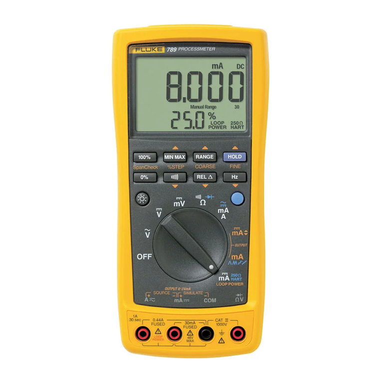
In this example, we will use
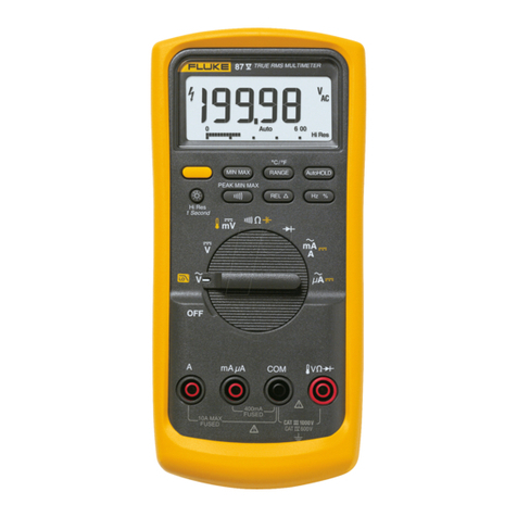
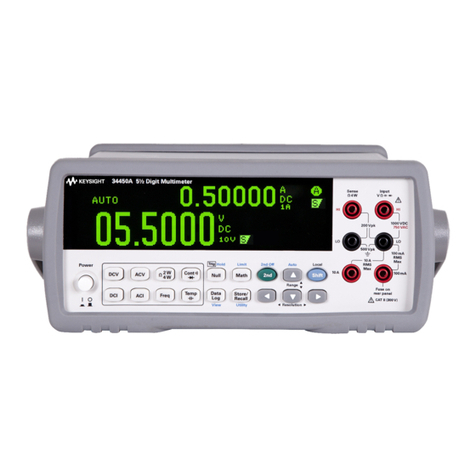
the Fluke 787 Process Meter.
Although the operating controls
vary, this application can also be
performed using the Fluke 707,
715, and 705 loop calibrators.
1. Disconnect the main loop
transmitter and connect the
Fluke 787 to the loop with
the test leads plugged into
the center or “Simulate” ter-
minals of the calibrator (see
Figure 2).
2. Set the 787 rotary switch to
the mA Output mode. Set the
Fluke 787 to the 4-20 mA
output mode. Make connec-
tion for simulate mA. The
787 is now outputting a pre-
cise 4 mA and is providing
operating power to the input
of the loop-powered isolator.
3. Place a Fluke 87, 187 or
equivalent multimeter (1 µA
resolution is ideal; 10 µA is
acceptable), set in the mA
measurement mode, on the
output side of the isolator to
monitor output current (see
Figure 2).
4. Adjust the zero control on
the isolator for a reading of
4.000 mA on the output
meter.
5. Step the input current to
20 mA using the % step
button ▲(25% or 4 mA
increase) and adjust the
span control on the isolator
to read 20.000 mA on the
output meter connected to
the isolator.
6. Step input current down
to 4 mA using the ▼ button
(25% or 4 mA decrease) and
check for a zero shift, adjust
if necessary.
7. At this point, basic zero
and span adjustments are
complete.
Check linearity
Fluke loop calibrators can eas-
ily check the linearity of your
loop isolator using the % step
buttons ▲ and ▼. Pushing
these buttons when in the out-
put mode increases or
decreases the output current in
25% steps. In the 4-20 mA
current mode these intermedi-
ate steps are at 8 mA (25%), 12
mA (50%), and 16 mA (75%).
To check linearity of the isola-
tor, push the associated % step
buttons up and down and con-
firm that the digital multimeter
(DMM) is reading the same
value as is shown on the loop
calibrator display. A variation
from expected values should be
compared to the linearity limits
stated by the manufacturer of
the loop-powered isolator.
Testing valve positioners
Electronic valve positioners
should receive periodic in-field
calibrations as part of preven-
tive maintenance programs.
Fluke loop calibrators are the
ideal test tools for these
checks. Valve positioners vary
in design and valve type and
should be calibrated using spe-
cific instructions from the
individual manufacturer.
Quick operational checks can
be performed using a field cali-
brator as a signal source while
observing the valve stem posi-
tion, mechanical position
indicators, or flow indicators as
input changes are made. Fluke
loop calibrators provide a con-
venient source for simulating
the controller output to a valve
positioner.
The following example
shows a general method for an
in-field operational check of a
valve fitted with an electronic
valve positioner. These meth-
ods may be adapted to various
types of valves, however, man-
ufacturer’s specific instructions
should always be consulted for
proper and appropriate tech-
niques. In the following
example, valve operation and
movement is checked either by
feel or by observing valve stem
movement.

