Prolitec AirQ AQ1200 User manual

by Prolitec
AQ/PS/RZ 1200 & 1200-SOC
Original Instructions
Rev. 2015-05-15

AQ/PS/RZ 1200 2
Contents
Chapter 1: About AirQ 1200
Chapter 2: Cartridge Life & Room Size Table
Estimating Cartridge Life
Room-Size Table
Chapter 3: IMPORTANT SAFETY
INSTRUCTIONS
Appliance Precautions
Fragrance Precautions
Chapter 4: MOVING AND STORAGE
INSTRUCTIONS
Chapter 5: Appliance and Controls
Chapter 6: USER MAINTENANCE
Changing the Cartridge
O-Ring Replacement
Air Filters and Check Valve
Battery Replacement
Chapter 7: OPERATING INSTRUCTIONS
Unit Programming
Setting Scent Intensity
Scent Control
Chapter 8: INSTALLATION:
Diusion via HVAC system
Installation Kit for Appliance
Installation Kit for HVAC System DIusion
HVAC Pre-installation Checklist
Appliance Positioning
Appliance Installation
Injector Tube Installation
Chapter 9: INSTALLATION:
Diusion via Direct Indoor Fan
Installation Kit for Appliance
Installation Kit for Fan
Pre-installation Checklist
Appliance Positioning
Appliance Installation
Diusion Fan Installation
Chapter 10: Troubleshooting
Chapter 11: General Care and
Customer Support
Chapter 12: Specications

AQ/PS/RZ 1200 3Chapter 1 About AQ/PS/RZ 1200
About AQ/PS/RZ 1200
Welcome to a whole new world of air treatment from Prolitec, the technology leader in air care with scent.
The AQ1200 appliance is the most advanced commercial air-treatment system on the market today. It is the
world’s rst fully adjustable commercial air-treatment system engineered to serve indoor spaces.
AQ1200 is a patented, computer-controlled, always-on system capable of maintaining a constant, uniform
and controlled level of scent or odor neutralizer.
The AQ1200 converts fragrances and odor control formulations (“Agents”) into ultra-ne droplets for
controlled distribution as an aerosol or vapor directly into a room or via the airow of the HVAC system,
either through the central fan unit (CFU) or at suitable locations in the branched ductwork. It is designed for
permanent installation on a wall in the area to be treated or integrated with the CFU.
The AQ1200 is managed by an on-board computer that is fully adjustable, enabling intensity settings to
match space sizes from 1,800 to 150,000 cubic feet (50-4,200 cubic meters) per appliance. The AQ1200 is
programmable, capable of executing 21 distinct start and stop times, repeatable daily or weekly. Utilizing
up to 21 programs and the full range of 50 intensity settings allows you to optimize the fragrance levels
depending on peak and non-peak occupancy in the space. This new feature can save you money on
fragrance AND service visits. Multiple appliances can work together on the same or multiple CFUs to treat
the air in the same spaces served by the HVAC. Multiple appliances can work together in the same space.
Typical AQ1200 applications include air treatment to enhance or improve indoor air quality including
odor cancelling, and ambient scenting in public spaces such as casinos, malls, hotels, theaters, ballrooms,
convention centers, hospitals, retirement and assisted living facilities, schools and restrooms. A single
AQ1200 can do both odor control and ambient scenting at the same time.
The AQ1200 with Prolitec odor control formulations and fragrances will cancel a wide range of oensive
odors and replace them with pleasant scents available from the Prolitec fragrance catalog or custom
developed to meet client requirements.
The AQ1200 works by generating ultra ne, ultra-light droplets approximately 1 micrometer (µm) in
diameter. By comparison, a droplet from a typical pressurized aerosol spray can is 50 microns (50000
nanometers) in diameter or 50 times larger than an AQ1200 droplet. In terms of weight and volume of
liquid, the comparison is even more dramatic. A 50-micron aerosol droplet is 125,000 times heavier than a
1 µm AirQ droplet.1 (See also Table 1 below.) This tiny AirQ droplet oers many performance benets over
a conventional aerosol including: completely uniform distribution of the treatment agent; 50 times more
exposed surface area; and the absence of any liquid deposits on surfaces such as the interior surfaces in an
HVAC system.
AQ1200 is simple to install and program for specic room size, airow conditions, and desired scent
intensity. Minimal maintenance is required beyond the periodic change of the disposable fragrance
cartridge, inspection and annual replacement of three O-rings, and a simple wipe down or dusting of
exterior surfaces. Once installed in the right location, AQ1200 will outperform any other system, providing
completely uniform scent distribution.
The AQ1200’s advanced technology creates a scent eect with a smaller quantity of fragrance ingredients
than any other method. The chemicals employed in making AQ1200 fragrances are fully compliant with
the most restrictive air-quality and inhalation standards. AQ1200 generates no harmful VOCs and uses no
ethanol or propellants. Quite simply, used as directed, AQ1200 is the greenest, most eco- friendly way to
introduce scent into an interior space with no negative impact on indoor air quality. This is not an accident.
1

AQ/PS/RZ 1200 4Chapter 1 About AQ/PS/RZ 1200
The scientists and engineers at Prolitec are committed to the highest ecological and human safety
standards.
This user guide is easy to read. It is also important to read. AQ1200 is a high-performance appliance that,
installed and used correctly, will meet the most demanding requirements.
Table 1. Prolitec AirQ Technology vs. Aerosol Spray Can Technology
Parameter Prolitec AirQ Technology Aerosol Spray Can
Droplet Diameter, µm 1 50
Volume per Droplet, µm3 0.52 65,450
Surface Area per Droplet, µm2 3 7,854
Relative Volume per Droplet 1 125,000
Relative Weight per Droplet 1 125,000
Number of Droplets per Equivalent Volume 125,000 1
Surface Area/Volume, µm-1 6.00 0.12
Relative Surface Area per Volume 50 1
©Prolitec Inc 2009, 2015
1

AQ/PS/RZ 1200 5Chapter 2 Cartridge Life & Room Size Table
Cartridge Life & Room Size Table
Estimating Cartridge Life
Estimating how long a cartridge will last and the number of days between services is critical to performing
an installation that can be serviced eiciently. This includes determining the number of AQ1200s needed
for a space. Please refer to AirQ’s ‘S3 (Sizing, Service & Success) Tool,’ available at AirQ Tools. The chart
below can be used as a rough guideline for sizing.
Room-Size Table
Normal O-Cycle
(NOC)
Short O-Cycle
(SOC)
Output Level
Range
Room Volume Range Room Volume Range
CFT CM CFT CM
1-5 1800-8100 51-229 6000-25000 170-708
6-10 10000-17400 283-492 30000-47100 849-1333
11-15 19300-27700 546-784 51100-66300 1446-1876
16-20 30000-39700 849-1124 70000-83600 1981-2366
21-25 42300-53400 1197-1511 86800-98900 2456-2799
26-30 56300-68600 1593-1941 101600-112000 2875-3170
31-35 71800-812000 2032-2425 114400-123500 3238-3495
36-40 89400-104800 2530-2966 125600-133600 3554-3781
41-45 108900-126200 3082-3571 135400-142300 3832-4027
46-50 130700-150000 3699-4245 143900-150000 4072-4245
These settings are suggested as a starting point. Start on the lower end of the range and adjust aer one
hour. Fragrance type, room size, number of fresh air changes per hour, temperature, humidity and user
preference will determine the nal setting. Best practice is to use AirQ’s ‘S3 Tool’ at AirQ Tools.
2

AQ/PS/RZ 1200 6Chapter 3 IMPORTANT SAFETY INSTRUCTIONS
IMPORTANT SAFETY INSTRUCTIONS
IMPORTANT SAFETY INSTRUCTIONS – SAVE THESE INSTRUCTIONS
Appliance Precautions
1. WARNING – When using electric products, basic precautions should always be followed, including the
following:
• Read all the instructions before using the product.
• Children should be supervised not to play with the appliance.
• Do not put ngers or hands into the product.
• The appliance must be operated in an upright or vertical position.
• The appliance should not be used with the door in the open position. The door is opened only to
perform a cartridge or program change.
• Never put your nose to the output of the AQ1200. Within 12 inches of the output, the fragrance is
highly concentrated. The improper inhalation of high concentrations of fragrance may cause irritation
including watery eyes, headache, cough and upper respiratory discomfort.
• This appliance is not intended for use by persons with reduced physical, sensory or mental capabilities,
or lack of experience and knowledge, unless they have been given supervision or instruction
concerning use of the appliance by a person responsible for their safety.
2. INSTRUCTIONS PERTAINING TO A RISK OF FIRE, ELECTRIC SHOCK, OR INJURY TO PERSONS
• The appliance is built to be plugged into an 110VAC or 220VAC power outlet. Must be used only with the
approved and included power supply. The UL and CE compliant power supply converts power to 12V
DC to power the appliance. The appliance must only be supplied at Safety Extra Low Voltage (SELV).
• If the supply cord is damaged, it must be replaced by the manufacturer, its service agent, or similarly
qualied persons in order to avoid a hazard.
• Unplug before cleaning.
• To reduce the risk of electric shock, the appliance should only be plugged into a properly grounded
outlet box. If there is any doubt as to whether an outlet box is properly grounded, a qualied electrician
should be consulted.
3

AQ/PS/RZ 1200 7Chapter 4 MOVING & STORAGE INSTRUCTIONS
Fragrance Cartridge Precautions
• Use only AirQ by Prolitec fragrance cartridges.
• Read the Consumer Product Safety Information Sheet and the Material Safety Data Sheet provided
with each shipment of Cartridges. Insure that these information sheets are available for review by
employees.
• Use latex gloves to handle a Cartridge to avoid the liquid getting on hands. The AirQ fragrances
are formulated so as to not be harmful in contact with the skin, but the concentrated nature of the
fragrances may make the scent diicult to remove from hands and skin.
• Wash your hands aer all contact with Cartridges or fragrance.
• While AirQ Air Treatment Agents do not contain ingredients deemed harmful to the skin, if there is skin
contact, wash with soap and water. If there is contact with the eyes, irrigate the eye with fresh water for
5 minutes. If there is any eye irritation, consult a physician immediately.
MOVING AND STORAGE INSTRUCTIONS
1. Remove the cartridge.
2. Unscrew and remove the long round-head screws in the lower corners.
3. Li the appliance upward, o the mounting posts.
4. Unplug the appliance.
5. Unscrew the mounting plate.
6. Store at -4°F (-20°C) to 158°F (70°C), 5% to 95% humidity
3& 4


AQ/PS/RZ 1200 9Chapter 6 USER MAINTENANCE
USER MAINTENANCE
Changing the Cartridge
1. Unlatch and open the door to access the cartridge: The door should be opened only to perform a
cartridge or programming change. When in use, the door must be closed.
2. Press POWER button to turn appliance OFF.
3. Remove air nozzle (located on the side of the cartridge head) by rotating 90 degrees and pulling
towards you. (See Fig. 1)
4. Detach injector hose and hose connector from the cartridge output port (located on the top of the
cartridge head). This is done by unscrewing the hose connector from the cartridge output port and
pulling out.
5. Remove cartridge from appliance enclosure.
6. Install new cartridge, place and tighten hose connector rmly on cartridge output port.
7. Insert air nozzle and rotate the handle 90 degrees until secured (by stem retaining tab on cartridge
head). (See Fig. 2)
8. Turn appliance ON. Verify that the plume is not escaping inside the appliance and that all connections
are tight. Close the door when complete.
Fig. 1 Fig. 2
O-Ring Replacement (each year or as needed)
1. Replace the air nozzle’s three O-rings (PN 8212) if worn or damaged. Replace as needed and/or each
year for preventative maintenance.
2. If there is any fragrance that leaks during the cartridge installation, clean it carefully with a paper towel
and some ethanol or another alcohol.
6
AQ/PS/RZ 1200 10Chapter 6 USER MAINTENANCE
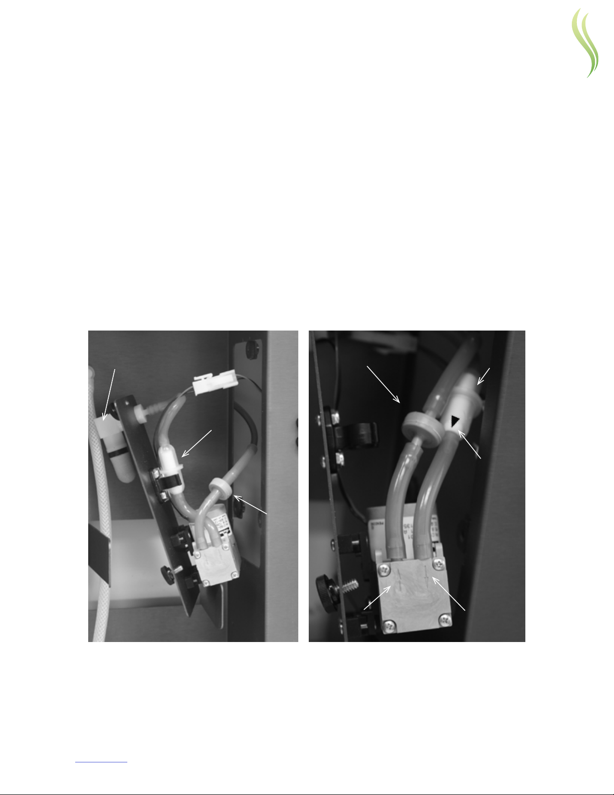
Air Filters and check valve
(every 6 months or sooner depending on use)
AQ1200 is equipped with two stages of air ltration and a check valve system.
The rst stage is a sintered lter (PN 10417). It is can be unscrewed and washed with clean water as
needed. Replace every six months.
The second stage lter (PN 5251) collects ne dust. Replace every 6 months or sooner depending on use. It
is accessible behind the air pump panel. A layer of black dust on top of the ltering media is a sign that the
lter should be replaced. To replace it, unscrew the 3 knobs to open the panel and exchange the lter aer
pulling o the rubber tubing from both sides of the lter. Note the small triangle showing the normal air
ow direction and position lter accordingly as shown below.
The check valve (PN 10200) should be replaced every six months. It is also located behind the panel. Note
the position of the check valve. Replace check valve accordingly as shown below.
Reinstall the panel and screw the three knobs back in place being careful not to strip the threads. The
screws should align and go in easily.
Check
Valve
Second Stage
Filter
Triangle
Pointing Down
Arrow
Pointing
Down
Arrow
Pointing
Up
First Stage
Filter
Second Stage
Filter
Check
Valve
6

AQ/PS/RZ 1200 11Chapter 6 USER MAINTENANCE
Battery Replacement (approximately every two years)
(Requires 3 Volt CR2032 Lithium Battery, PN 8111)
1. Unlatch and open the door to access the enclosure.
2. Using a pair of tweezers or needle-nose pliers, remove battery from the center opening of the battery
grommet. The battery is located on the lower front corner of the silver bracket.
3. Insert the new CR2032 battery. The positive side of the battery should face your right while looking at
the front of the appliance. The battery will have a + or – marking on a side.
NOTE: The battery is necessary to safeguard your program and to
ensure operation will resume automatically even aer several days of
a power interruption. The battery should be replaced at least every 2
years for proper reliable system operation.
6

AQ/PS/RZ 1200 12Chapter 7 OPERATING INSTRUCTIONS
OPERATING INSTRUCTIONS
Unit Programming
1. Unlock and open the door
2. Turn on the power by pressing ON/OFF button in the upper le corner of the control panel.
3. Set the Clock
• Turn the dial to Set Clock. The day-of-week icon will blink.
• Adjust the day forward or backwards using the +/- buttons on the right side of the control panel.
• Press the Set button on the lower le corner of the LCD display. The time will blink.
• Adjust the time forward or backwards using the +/- buttons. AM or PM is indicated on the right side
of the time digits.
4. 24/7 Mode
• If you want the AQ1200 to run continuously -7 days a week, 24 hours a day 7 Days a week turn the
dial to Run 24/7. If not, skip to Step 5.
• You can adjust the fragrance intensity level (1 to 50) using the +/- buttons. Refer to Setting Scent
Intensity for the intensity level to set.
5. Set multi-program timer
• Turn the dial to Set Program. The Program icon comes on.
• The day-of-week icons will all blink, indicating you are selecting all days with the same program. If
you want to program a specic day, use the +/- buttons to select the day. You can set maximum of
3 on/o programs same for every day or individually for each day. Aer selecting the day, press the
Set button to advance.
• Now the “1” icon is turned on to indicate you are setting program 1. The Rate digits blink to prompt
you to set the rate. You may set to any value between 1 to 50, or set to 0 to disable the program.
Press the Set button to advance.
• If you set the rate to 0, then the current and subsequent programs are all disabled. For example, if
the rate for program 2 is 0, then program 2 and 3 are disabled.
• If you set a non-zero rate, then the rate digit changes to “S” to indicate start time. The hour digit
should blink to prompt you to set the start hour. Use the +/- buttons to set the hour. Then press the
Set button to advance and set the minute. Press the Set button to advance.
• The rate digit now changes to “E” to indicate you are setting the end time. Use the +/- buttons to
set the end time. Press the Set button to advance to the next program.
• Program icon 2 should now turn on. Use the +/- and Set buttons to set the start and end times
for program 2 and then for program 3. Note that if you need only 1 or 2 programs for the day, you
simply disable the subsequent programs by setting its rate to 0.
• Aer setting the programs, turn the dial to Run Program.
7

AQ/PS/RZ 1200 13Chapter 7 OPERATING INSTRUCTIONS
HINT:To set same programs for Monday to Friday, you may set the
programs for every day rst and then disable Saturday and Sunday. You
may review the programs by doing the same as in programming. Just
beware not to accidentally set the every day programs as this will also
set and change the programs of all the days.
Setting Scent Intensity
1. Consult the Room Size Table, which provides a setting for the size in cubic feet (length x width x ceiling
height) of the space you are treating. Use the indicated intensity setting as a starting point from which
you can increase or decrease to taste. Number of fresh air changes per hour and user preference will
aect settings.
2. Press the power button on. Turn the dial to Program and set the intensity level with the +/– keys. You
will see the level numbers (1 to 50) on the right side of the screen.
Hint: There are many variables to nding the scent level that works:
size, airow, number of fresh air changes per hour, number of
people in the space and, most of all, user preferences. Experiment
with dierent levels until you are satised. Utilize the S3 Tool.
Scent Control
If you followed the Room-Size Table or S3 Tool, you have set AQ1200 to the low end of the range for your
room size. If aer one hour you feel the scent is not detectable, increase the setting by about 10%. For
example, if your start setting was 20, increase it by 10%, or to setting 22. Keep increasing until you and
others in the space can detect a slight scent throughout the space.
The Last Step
1. Set the appliance to either 24/7 or Run Program.
2. Make sure the power is on. The blue light will show through the button.
3. Close and lock the door, storing the key in a known place.
7

AQ/PS/RZ 1200 14Chapter 8 INSTALLATION: Diusion via HVAC System
INSTALLATION: Diusion via HVAC System
Installation Kits
Installation Kit for Appliance (included)
1. One (1) AQ1200 appliance (not pictured) with:
2. Four (4) drywall anchors for mounting in drywall
3. Four (4) lead anchors for mounting in concrete
4. Four (4) screws and (4) washers for mounting in drywall and concrete
5. Four (4) #10 self-tapping sheet metal screws for mounting in sheet metal
6. Plume connector: A: (1) Tubing assembly; B: (1) Connector; C: (2) Washers; D: (1) Nut; E: (1) Cable Tie
2
6
543
E
E
C
B
A
8

AQ/PS/RZ 1200 15Chapter 8 INSTALLATION: Diusion via HVAC System
Installation Kit for HVAC System Diusion (included)
1. One (1) Prolitec injector tube for diusion into HVAC system
2. Three (3) #10 self-tapping sheet-metal screws for mounting the injector tube in sheet metal
3. Five (5) feet of injector hose
1
2
3
HVAC Pre-installation Checklist
This checklist should be completed before the install date.
1. Conrm the area to be targeted for air treatment.
2. Determine the Air Handling Unit or duct that serves the target area.
3. Make sure the AHU does not use an open gas ame.
4. Find and mark the optimal insertion point for the Injector Tube. (See “Appliance Positioning” below)
5. Find and mark the exact location for placement of the appliance. (See “Appliance Positioning” below)
6. Note the distance between the insertion point and the proposed appliance location. (NEVER MORE
THAN 5 FEET and there should NEVER be a LOW POINT in the hose run.)
7. Determine and mark the location for the 110 or 220V AC power outlet (NEVER DIRECTLY BELOW THE
appliance).
8

AQ/PS/RZ 1200 16Chapter 8 INSTALLATION: Diusion via HVAC System
Appliance Positioning
It is important to nd an insertion point where the plume output will be smoothly drawn into and mixed
with the airow. This usually means those parts of the AHU where the static pressure is negative. Ideal
locations include:
• Before the supply fan with injection through the wall of the AHU. Positioning immediately before the
fan and aer the coils if possible or in the mixed air chamber.
• Behind the blower with the whole appliance mounted inside the AHU in the mixed air chamber.
• Outside the AHU in the Supply air duct.
Best practice when installing in an AHU is to place the injector tube aer the heating and cooling coils. If
this is not possible, the Plume output can pass over hot water, steam, chilled water, and DX coils.
Open gas ames should absolutely be avoided. If installation must be over gas heated coils or open
gas ames, contact Prolitec Technical Support.
The best location for the Appliance is below the injector tube (Fig. 15). The injector hose should be run
upward as short a distance as possible and NEVER MORE THAN 3 FEET. If an upward injector hose run is
not possible, care should be taken support the hose to prevent sagging or any low spot in the run to avoid
any possibility of condensation and liquid collection which will block the plume output. The injector hose
is prone to stretching, so support points should be placed every 6 inches on horizontal runs. Give the hose
a slight upward slant along its run (See Fig. 16). The hose must not be run horizontally. A strong tape (such
as Venture tape) may be used to support short runs. The hose may be run through PVC pipe for longer
distances.
Injector Tube
AQ1200
Injector Hose
Power
Junction Box
Fig. 15
8

AQ/PS/RZ 1200 17Chapter 8 INSTALLATION: Diusion via HVAC System
Fig. 16
CORRECT INCORRECT
Appliance Installation
1. The appliance is wall-mounted. Place the appliance onto the desired location on the wall or AHU and
ensure that it is level.
2. Fasten the appliance to the wall or AHU using necessary screws.
3. Connect the power cord to a junction box or attach an AC plug to the cord and connect to a nearby
outlet. Open the enclosure door and unscrew the aluminum cap of the waterproof collar located on top
of the appliance enclosure. Remove and set aside the grommet (Fig. 1).
4. Assemble the Plume Connector:
• Insert washer and insert assembly, threaded side rst, through hole on top of the appliance (Fig. 17).
• Insert another washer and secure with nut. Use pliers to ensure a watertight seal (Fig. 18).
• Push the tubing assembly over the barbed tting (Fig. 19).
• Important: Secure with cable tie (Fig. 20).
Thread
Fig. 17 Fig. 18 Fig. 19 Fig. 20
8

AQ/PS/RZ 1200 18Chapter 8 INSTALLATION: Diusion via HVAC System
Injector Tube Installation
The injector tube is installed directly into the AHU or ductwork. Its orientation can be adjusted relative to
airow.
• For installations into the negative/suction side of the AHU fan, orient the tube with the elbow pointed
upwards, so that any plume condensation will drip back down the tube.
• For installations aer the supply fan, such as in a supply duct, it is necessary to congure and orient
the Injector Tube to obtain a good aspiration of the output into the air stream. The injector tube
should be pointed in the direction of the airow and inclined approximately 45o upward. Turbulence
in the airow can prevent even aspiration of the plume. It is best to place the tube in a straight
section of duct, and far away from any turns, branches, or cross-section changes as practical, and not
immediately aer the supply fan.
1. At the insertion point, drill a hole using a ½” drill bit.
2. Insert the Injector Tube through the hole.
3. Find an orientation of the injector Tube that appears to produce a good draw of air into the end of the
barb.
4. Fasten the ange using the three #10 sheet metal screws.
5. Turn the appliance on and verify that a plume is produced.
6. Before attaching the Injector hose to the injector, verify that the plume can ow easily through the
injector. This can be done by placing the end of the hose ½ inch away from the injector and verifying
that the plume is being drawn in (a ashlight will make the plume easier to see). If the plume does not
rise into the hose, adjust the orientation of the Injector Tube until aspiration is achieved.
7. Attach the Injector hose onto the hose barb of the Injector Tube.
For Cartridge Installation – See “Changing the Cartridge”
8

AQ/PS/RZ 1200 19Chapter 9 INSTALLATION: DIusion via Direct Indoor Fan
INSTALLATION: Diusion via Direct Indoor Fan
(Product# AQ1200-FAN)
Installation Kits
Installation Kit for Appliance (included)
1. One (1) AQ1200 appliance (not pictured) with:
2. Four (4) dry wall anchors for mounting in drywall
3. Four (4) lead anchors for mounting in concrete
4. Four (4) screws and (4) washers for mounting in drywall and concrete
5. Four (4) self-tapping sheet metal screws for mounting in sheet metal
6. Plume connector: A: (1) Tubing assembly; B: (1) Connector; C: (2) Washers; D: (1) Nut; E: (1) Cable Tie
2
6
543
E
E
C
B
A
9

AQ/PS/RZ 1200 20Chapter 9 INSTALLATION: DIusion via Direct Indoor Fan
Installation Kit for Fan (accessory sold separately)
1. One (1) Prolitec Diusion fan and cable for direct indoor diusion
2. Three (3) drywall anchors for mounting fan onto dry wall
3. Three (3) lead anchors for mounting in concrete
4. Three (3) screws for mounting in drywall and concrete
5. Five (5) feet of small cable raceway for fan cable
6. Five (5) feet of OD injector hose
1
4
5
6
3
2
9
This manual suits for next models
5
Table of contents
Other Prolitec Accessories manuals

Prolitec
Prolitec AIRQ AQ 570 CM User manual

Prolitec
Prolitec AirQ 270 TT User manual

Prolitec
Prolitec AirQ 380 User manual

Prolitec
Prolitec AirQ AQ550 User manual

Prolitec
Prolitec AQ1570 User manual

Prolitec
Prolitec AIRQ AQ160 User manual

Prolitec
Prolitec AirQ 1570 User manual

Prolitec
Prolitec AirQ AQ150 User manual

Prolitec
Prolitec AirQ AQ 1270 TT User manual

Prolitec
Prolitec AirQ AQ1200WHTTT-SS User manual


