REV 7.0.0 / PL-TRA-STARTUP-EN 4
Part 2 - Installing the Components
Sensors and Accessories
1. Room sensor: Install 60” from the oor. Avoid sunny or outdoor
walls, diusers and return grills. (Especially with bypass boxes.)
Beware of electrical boxes (light dimmers)!
(PL-T200 / PL-T500 / PL-T100)
2. Outside air temperature sensor: Install under air inlet hood or on
the unit’s north side IN THE SHADE!
(PL-OAS)
3. Supply air temperature sensor: Install after the bypass damper
junction. (PL-DS)
Return air temperature sensor: Install before the bypass damper
junction (no turbulence). (PL-DS)
4. Static pressure sensor: To be installed 2/3 of the main ventilation
duct’s length. (PL-MLP)
5. Proof of fan (ow switch): Install near the supply air temperature
sensor (no turbulence). Plug the high pressure (+) Pitot tube in the
air duct. Remove the low pressure cap and leave free. (AFS)
6. CO Sensor: Install in the return duct before the bypass junction.
(CO)
7. Bypass damper actuator: Mark the damper position on the shaft
and validate its opening direction.
1
23
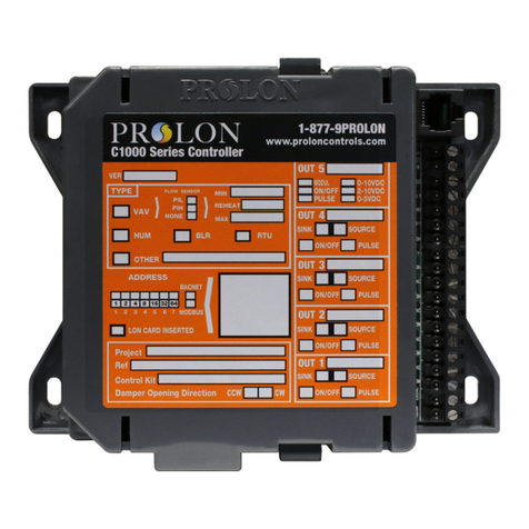
VAV Zone Controller
•Verify / validate the rotation direction of each zone damper.
•Close the damper and rotate the actuator clamp to the closed posi-
tion using the clutch button.
•Install the zone controller on the damper and set in place with
screws and bracket.
•While pressing the actuator’s clutch button, turn the clamp manually,
the damper should turn freely (slight o axis movement).
•Adjust mechanical stoppers to prevent overtravel. Full rotation of
actuator should match that of damper.
•Get the identication address of each zone and write it down inside
the cover (or the back plate) of its’zone thermostat (very convenient
for service calls).
Part 2 : Installing the components
VAV Zone Controller
oVerify / validate the rotation direction of each zone
damper.
oInstall the zone controller on the damper and set in place
with screw.
oWhile pressing the actuator’s clutch button, turn the clamp,
the damper should turn freely (a slight off axis movement).
oAdjust mechanical stoppers on actuator to match the full
rotation of the damper.
oGet the identification address of each zone and write it
down inside the cover (or the back plate) of its’ zone
thermostat (very convenient for service calls).
Room sensor: Install 60in from the floor.
Avoid sunny or outdoor walls, diffusers and return grills.
Beware of electrical boxes (lit dimmers)!
Outside air temperature sensor: Install under air inlet hood or on the unit’s north side
IN THE SHADE!!!
Supply air temperature sensor: Install after the bypass damper junction
Return air temperature sensor: Install before the bypass damper junction (no turbulence)
Static pressure sensor: To be installed 2/3rds of the main ventilation duct’s length.
Proof of fan (flow switch): Install near the supply air temperature sensor (no turbulence).
Plug the high pressure (+) Pitot tube in the air duct. Remove the low pressure cap and
leave free.
CO2 Sensor: Install in the return duct before the bypass junction.
Bypass damper actuator: Mark the damper position on the shaft and validate its
opening direction.
6
Part 2 : Installing the components
VAV Zone Controller
oVerify / validate the rotation direction of each zone
damper.
oInstall the zone controller on the damper and set in place
with screw.
oWhile pressing the actuator’s clutch button, turn the clamp,
the damper should turn freely (a slight off axis movement).
oAdjust mechanical stoppers on actuator to match the full
rotation of the damper.
oGet the identification address of each zone and write it
down inside the cover (or the back plate) of its’ zone
thermostat (very convenient for service calls).
Room sensor: Install 60in from the floor.
Avoid sunny or outdoor walls, diffusers and return grills.
Beware of electrical boxes (lit dimmers)!
Outside air temperature sensor: Install under air inlet hood or on the unit’s north side
IN THE SHADE!!!
Supply air temperature sensor: Install after the bypass damper junction
Return air temperature sensor: Install before the bypass damper junction (no turbulence)
Static pressure sensor: To be installed 2/3rds of the main ventilation duct’s length.
Proof of fan (flow switch): Install near the supply air temperature sensor (no turbulence).
Plug the high pressure (+) Pitot tube in the air duct. Remove the low pressure cap and
leave free.
CO2 Sensor: Install in the return duct before the bypass junction.
Bypass damper actuator: Mark the damper position on the shaft and validate its
opening direction.
4
Part 2 : Installing the components
VAV Zone Controller
oVerify / validate the rotation direction of each zone
damper.
oInstall the zone controller on the damper and set in place
with screw.
oWhile pressing the actuator’s clutch button, turn the clamp,
the damper should turn freely (a slight off axis movement).
oAdjust mechanical stoppers on actuator to match the full
rotation of the damper.
oGet the identification address of each zone and write it
down inside the cover (or the back plate) of its’ zone
thermostat (very convenient for service calls).
Room sensor: Install 60in from the floor.
Avoid sunny or outdoor walls, diffusers and return grills.
Beware of electrical boxes (lit dimmers)!
Outside air temperature sensor: Install under air inlet hood or on the unit’s north side
IN THE SHADE!!!
Supply air temperature sensor: Install after the bypass damper junction
Return air temperature sensor: Install before the bypass damper junction (no turbulence)
Static pressure sensor: To be installed 2/3rds of the main ventilation duct’s length.
Proof of fan (flow switch): Install near the supply air temperature sensor (no turbulence).
Plug the high pressure (+) Pitot tube in the air duct. Remove the low pressure cap and
leave free.
CO2 Sensor: Install in the return duct before the bypass junction.
Bypass damper actuator: Mark the damper position on the shaft and validate its
opening direction.
5
7
