Tolomatic IMA Series User manual

2700-4001_22 IMA Manual 1 Last Revision: 12/14/2021
MANUAL
For Installation, Maintenance
and Operation
IMA Series Actuators
LINEAR SOLUTIONS MADE EASY

2700-4001_22 IMA Manual 2 Last Revision: 12/14/2021
Original instructions in English. Translations in community languages supplied as required.
Information furnished is believed to be accurate and reliable. However, Tolomatic assumes no responsibility for its
use or for any errors that may appear in this document.
Tolomatic reserves the right to change the design or operation of the equipment described herein and any
associated motion products without notice. Information in this document is subject to change without notice.

2700-4001_22 IMA Manual 3 Last Revision: 12/14/2021
CONTENTS
CONTENTS....................................................................................................................................................................................3
LIST OF FIGURES & TABLES ......................................................................................................................................................5
1: SAFETY .....................................................................................................................................................................................7
•1.0 SAFETY ......................................................................................................................................................................7
•1.1 SAFETY SYMBOLS .......................................................................................................................................................7
•1.2 SAFETY CONSIDERATIONS ...........................................................................................................................................8
2: IMA PRODUCT OVERVIEW....................................................................................................................................................10
•2.0 GENERAL DESCRIPTION.............................................................................................................................................10
•2.1 PRODUCT FEATURES.................................................................................................................................................10
•2.2 INSTALLATION ...........................................................................................................................................................10
•2.3 CABLE ROUTING........................................................................................................................................................11
•2.4 ACTUATOR ORIENTATION...........................................................................................................................................11
•2.5 EMC WIRING GUIDELINES .........................................................................................................................................12
•2.6 MOTION CONTROL SYSTEM SELECTION RECOMMENDATIONS.......................................................................................12
•2.7 IDENTIFICATION LABEL...............................................................................................................................................12
•2.5 CERTIFICATION .........................................................................................................................................................12
•2.6 MANUFACTURER .......................................................................................................................................................12
3: IMA ACTUATOR PRODUCT CONFIGURATION....................................................................................................................13
•3.1 TOLOMATIC IMA ACTUATOR SERIES CONFIGURATION .................................................................................................13
•3.2 STANDARD CONFIGURATIONS AND OPTIONS................................................................................................................13
•3.2.1 SCREW SELECTION ................................................................................................................................................15
•3.2.2 MOTOR VOLTAGE...................................................................................................................................................15
•3.2.3 INTERNAL HOLDING BRAKE OPTION.........................................................................................................................15
•3.2.4 STANDARD MOUNTING OPTIONS .............................................................................................................................15
•3.2.5 MOUNTING OPTIONS ..............................................................................................................................................15
•3.2.6 STANDARD ROD END..............................................................................................................................................15
•3.2.7 ROD END OPTIONS ................................................................................................................................................16
•3.2.8 OTHER OPTIONS ....................................................................................................................................................16
•3.2.9 SPECIAL OPTIONS ..................................................................................................................................................16
•3.2.10 FEEDBACK DEVICE ...............................................................................................................................................16
•3.2.11 CABLE &CONNECTOR(S)......................................................................................................................................16
•3.2.12 SERVO DRIVE ......................................................................................................................................................17
•3.2.13 ROCKWELL AUTOMATION PARTNERNETWORK™PROGRAM....................................................................................17
4: IMA MECHANICAL INSTALLATION ......................................................................................................................................18
•4.1 TOLOMATIC IMA ACTUATOR SYSTEM CONFIGURATION ................................................................................................18
•4.2 GENERAL OPERATION ...............................................................................................................................................18
•4.3 COLD TEMPERATURE STARTUP PROCEDURE ..............................................................................................................19
•4.4 PLANNING YOUR INSTALLATION..................................................................................................................................19
•4.4.1 ALIGNMENT............................................................................................................................................................20
•4.4.2 SIDE LOAD CONSIDERATIONS..................................................................................................................................20
•4.5 MECHANICAL INSTALLATION INSTRUCTIONS.................................................................................................................20
•4.6 MOUNTING................................................................................................................................................................22
•4.5 FIELD INSTALLATION OF ARO (ANTI ROTATION)OPTION..............................................................................................23
5: ELECTRICAL INSTALLATION ...............................................................................................................................................25
•5.1 CONNECTOR ORIENTATION........................................................................................................................................25

2700-4001_22 IMA Manual 4 Last Revision: 12/14/2021
•5.2 FEEDBACK INFORMATION ...........................................................................................................................................25
•5.3 FEEDBACK COMMUTATION .........................................................................................................................................26
•5.4 FEEDBACK COMMUTATION DETAILS............................................................................................................................26
•5.5 FEEDBACK SPECIFICATIONS.......................................................................................................................................29
•5.6 THERMAL SENSOR SPECIFICATIONS ...........................................................................................................................30
•5.7 CONNECTOR PINOUTS...............................................................................................................................................31
•5.7.1 TOLOMATIC STANDARD -DT1 .................................................................................................................................31
•
5.7.2
A
LLEN
B
RADLEY
MP
M
OTOR
S
ERIES
-
DA1
.............................................................................................................36
•
5.7.3
A
LLEN
B
RADLEY
VP
M
OTOR
S
ERIES
-
DA2
..............................................................................................................37
•
5.7.4
B
OSCH
R
EXROTH
MSK
M
OTOR
S
ERIES
-
DB1
.........................................................................................................38
•
5.7.5
C
ONTROL
T
ECHNIQUES
FM
M
OTOR
S
ERIES
-
DE1
..................................................................................................39
•
5.7.6
C
ONTROL
T
ECHNIQUES
NT
M
OTOR
S
ERIES
-
DE2
...................................................................................................41
•
5.7.7
L
ENZE
MCS
M
OTOR
S
ERIES
-
DL1
.........................................................................................................................42
•
5.7.8
S
IEMENS
1F
M
OTOR
S
ERIES
-
DS1
.........................................................................................................................44
6: IMA OPERATION AND START UP CONSIDERATIONS .......................................................................................................45
•6.1 ATTACHING CABLES &HOMING /MECHANICAL TRAVEL LIMITS.....................................................................................45
•6.2 BRAKE......................................................................................................................................................................45
7: IMA REPAIR AND MAINTENANCE........................................................................................................................................47
•7.1 LUBRICATION ............................................................................................................................................................47
•7.2 PERIODIC MAINTENANCE ...........................................................................................................................................47
•7.3 PROCEDURE FOR LUBRICATION ..................................................................................................................................50
•7.4 TOLOMATIC IMA MAINTENANCE AND REPAIR ..............................................................................................................50
•7.5 STORAGE RECOMMENDATIONS ..................................................................................................................................52
APPENDIX A: SPECIFICATIONS ...............................................................................................................................................53
•A.1 ACTUATOR SPECIFICATIONS ......................................................................................................................................53
•A.2 MOTOR SPECIFICATIONS:..........................................................................................................................................53
•A.3 BRAKE SPECIFICATIONS ............................................................................................................................................53
•A.4 SPEED VS THRUST GRAPHS ......................................................................................................................................53
•A.5 CALCULATING RMS THRUST AND VELOCITY FOR CONTINUOUS DUTY: .........................................................................53
•A.6 CRITICAL SPEED .......................................................................................................................................................54
•A.7 BALL &ROLLER SCREW LIFE.....................................................................................................................................54
•A.8 STANDARD THERMAL SWITCH SPECIFICATIONS............................................................................................................54
APPENDIX B: TROUBLESHOOTING PROCEDURE.................................................................................................................55
APPENDIX C: WARRANTY ........................................................................................................................................................56
•C.1 WARRANTY ..............................................................................................................................................................56
APPENDIX D: DECLARATION OF CONFORMITY ....................................................................................................................58

2700-4001_22 IMA Manual 5 Last Revision: 12/14/2021
LIST OF FIGURES &TABLES
Figure 1.1: Do not carry IMA by connectors or cables. ..................................................................................................................9
Figure 2.1: Tolomatic IMA Actuator ..............................................................................................................................................10
Figure 2.2: IMA major components ..............................................................................................................................................10
Figure 2.3: Recommended routing of Tolomatic IMA Actuator cabling. .......................................................................................11
Figure 2.4: 1. & 2. Recommended IMA thrust rod orientation is down or horizontal. 3. Due to increased risk of contamination
and ingress never orient the IMA actuator with the thrust rod up.................................................................................................11
Figure 2.2: Tolomatic IMA Actuator identification label. ...............................................................................................................12
Figure 3.1: Tolomatic IMA Actuator ordering codes and descriptions..........................................................................................14
Figure 3.2: Standard mounting for the IMA is four (4) threaded holes on the front face (rod end) of the actuator.......................15
Figure 3.3: Optional mounting for the Tolomatic IMA Actuator.....................................................................................................15
Figure 3.4: Standard rod end for the IMA is internal threads........................................................................................................15
Figure 3.5: Rod End Options for the Tolomatic IMA Actuator ......................................................................................................16
Figure 3.5: Rod End Options for the Tolomatic IMA Actuator ......................................................................................................16
Figure 4.1: Typical connections for a single-axis system with an Tolomatic IMA Actuator with optional brake to a RSW servo
system drive .................................................................................................................................................................................18
Figure 4.2: Side load must not exceed maximum values represented by the lines in the graph..................................................20
Figure 4.3: Do not carry IMA by connectors or cables. ................................................................................................................21
Figure 4.4: Use straps and winch to position heavy IMA actuator................................................................................................21
Figure 4.5: Hold thrust rod stationary using a wrench on the flats of the rod end when attaching accessories, linkages or load to
the actuator. Two wrenches are used here: The crescent wrench prevents the thrust rod from rotating, the torque wrench will
fasten the spherical rod eye option to the actuator rod end. Torque values provided in Table 4.1 ..............................................22
Table 4.1: Rod end torque recommendations ..............................................................................................................................22
Table 4.2: Tapped hole torque recommendations........................................................................................................................23
Table 4.3: Mounting Plate (MP2) Clearance Hole Bolt and Torque Requirements (Minimum Fastener Grade 8.8)....................23
Table 4.4: Front Flange Mount (FFG) Clearance Hole Bolt and Torque Requirements (Minimum Fastener Grade 8.8).............23
Figure 4.6: View of ARO (Anti Rotate Option)..............................................................................................................................23
Figure 5.3: Connector rotation. Note that the Tolomatic standard connectors may be rotated from -90° to +180° allowing for
cables to connect toward the front (rod end, as manufactured), to either side, both sides, or back of actuator. .........................25
Figure 5.4: Drawing of box mount connectors used on some Tolomatic IMA Actuators. .............................................................25

2700-4001_22 IMA Manual 6 Last Revision: 12/14/2021
Figure 5.5: Thrust rod movement relative to motor rotation .........................................................................................................26
Figure 5.6: Back EMF Voltage vs Electrical Angle .......................................................................................................................27
Figure 5.7: Back EMF Voltage Phase to Phase vs Electrical Angle.............................................................................................27
Figure 5.8: Hall Alignment ............................................................................................................................................................28
Figure 5.9: Motor rotational position at 0......................................................................................................................................28
Figure 5.10: Motor rotational position at 90..................................................................................................................................29
Figure 6.1: Fastest Engage / Disengage time, least protection....................................................................................................45
Figure 6.2: Increased Engage / Disengage time, best protection.................................................................................................46
Figure 7.1: Roller Screw Lubrication Interval Graph.....................................................................................................................48
Figure 7.1: A standard grease zerk allows periodic relubrication for Tolomatic IMA Actuators. This can be done without
removing the actuator from its installation. ...................................................................................................................................50

2700-4001_22 IMA Manual 7 Last Revision: 12/14/2021
1: SAFETY
1.0 Safety
1.1 Safety Symbols
General
Read completely through the applicable sections of the manual before the equipment/unit is unpacked, installed or
operated. Pay careful attention to all of the dangers, warnings, cautions and notes stated in the manual.
Serious injury to persons or damage to the equipment may result if the information in the manual is not followed.
Safety Symbols
Items that are specifically marked DANGER, WARNING, CAUTION, PROHIBITIVE, MANDATORY ACTION, or
NOTE! are arranged in a hierarchical system and have the following meaning:
Indicates a very hazardous situation which, if not avoided, could result in death or serious injury. This signal word
is limited to the most extreme situations.
Indicates a potentially hazardous situation which, if not avoided, could result in death or serious injury.
Indicates a potentially hazardous situation which, if not avoided, may result in property damage, minor or moderate
injury.
Indicates Prohibited Action
Indicates Mandatory Action
Information that requires special attention is stated here.
WARNING! Normal operating temperature of weld actuator can range from 135 degrees F (57°C) to 175 degrees
F (79°C).

2700-4001_22 IMA Manual 8 Last Revision: 12/14/2021
1.2 Safety Considerations
Proper and Safe Use of Product
Fail Safe e-Stop Recommendations
A means for a fail safe e-stop is highly recommended to ensure equipment and personal safety. The e-stop should
provide a means to remove main power from the actuator to cease and prevent any unwanted motion.
Device Damage Prevention
To prevent permanent damage to the device, proper care should be taken not to exceed published voltage,
current, temperature, and load/force ratings. In addition, proper mechanical assembly and proper wiring should be
verified and safety measures checked before applying power to the complete equipment package.
The only field maintenance that may be performed on the IMA include lubrication and replacement of the rod wiper.
All other repair or maintenance for the IMA must be performed at Tolomatic.
Personal Safety
During normal operation the actuator can become hot, especially the motor housing. It is highly recommended to
display proper safety notices and implement proper safety measures to prevent contact with hot surfaces. In
addition, the case ground should be tied to an earth ground to prevent the presence of case voltage.
During normal operation, the actuator rod travels in and out creating a possible pinch point.
Proper guarding and signage must be used prevent entry into possible pinch zones and contact with hot surfaces.
It is highly recommended to display proper safety notices and implement proper safety measures to prevent
contact with hot surfaces.
Handling and Unpacking
When unpacking and handling the actuator, care should be taken not to drop the actuator as this can damage the
connectors, internal electronics, or cause misalignment of the actuator feedback device. Damage the internal
mechanical components may cause poor performance or render the actuator non-functional. Since this is an
electromechanical device, proper ESD measures should be taken to avoid static electricity from contacting the
signal and power lines of the device. as this can damage the internal mechanical components rendering the
actuator damaged or non-functional.
Packing and Transport
Package actuator to prevent damage during transport. It is recommended that the actuator be returned in its
original packaging. If the original packaging is not available, the follow these recommendations.
1. Foam in place if possible.
2. Reinforce ends of box with multiple layers of cardboard or wood to prevent the actuator
from breaking through the packaging during shipment.
3. Support the connectors or cables so that enough packaging or foam is in place to
prevent shipping damage.
4. It is best to ship one unit per container because individual items that are not isolated
with stable packaging (foam in place) from each other often get damaged during
shipment.
5. When shipping more than one unit in a single container, it is recommended to foam in
place to prevent damage during shipping to both the units and the packaging.
6. Add the RMA on the outside of the packaging. Failure to do so will delay processing.

2700-4001_22 IMA Manual 9 Last Revision: 12/14/2021
Figure 1.1: Do not carry IMA by connectors or cables.
The Tolomatic IMA Actuator weight range is approximately 3.0 to 42 kg ( 6.6 to 93 lb). Special care must be taken
when lifting this device. Do not carry by the connectors or cables. The connectors are not rated to support the
weight of the actuator.
Modifications to the Equipment
The manufacturer takes no responsibility whatsoever if the equipment is modified or if the equipment is used in any
way beyond performance specifications. Unauthorized modifications or changes to the equipment are strictly
forbidden, and void all warranties.
Repair and Maintenance
All power and supply media must be shut OFF before any work is performed on any equipment that is associated
with the Tolomatic IMA Actuator. The only field maintenance that may be performed on the Tolomatic IMA Actuator
is lubrication. All other repair or maintenance for the Tolomatic IMA Actuator must be performed at Tolomatic.
Requirement Regarding Personnel
All personnel must be completely informed regarding all safety regulations and the function of the equipment.
Risk Area and Personnel
When installed, pinch points are generated capable of high damaging forces. The risk area surrounding the
Tolomatic IMA Actuator must either be enclosed or clearly marked, including display signage in accordance with all
applicable national and international legal requirements. The risk area must be protected by a safety system that
stops the equipment if anyone enters the risk area. Personnel who enter the risk area must be authorized, trained
and qualified for the different tasks inside the risk area.

2700-4001_22 IMA Manual 10 Last Revision: 12/14/2021
2: IMA PRODUCT OVERVIEW
2.0 General Description
Tolomatic IMA Actuators
Figure 2.1: Tolomatic IMA Actuator
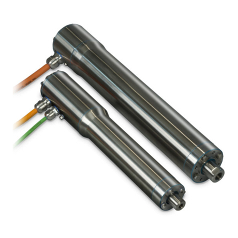
The IMA is a compact, durable, high force rod-style actuator. The IMA integrates a servo motor into the mechanical
design to minimize the overall envelope. The patented design allows for easy re-lubrication without disassembly for
extremely long service life.
2.1 Product Features
Figure 2.2: IMA major components
2.2 Installation
The IMA is a compact high force screw drive servo actuator. The IMA provides linear motion of the moveable rod

2700-4001_22 IMA Manual 11 Last Revision: 12/14/2021
developing the required thrust force and velocity in a variety of applications.
Before installation and commissioning of the equipment, this manual and all accompanying manufacturer
documents and manuals MUST be completely read by the appropriate personnel. All warning texts must be given
special attention.
2.3 Cable Routing
It is recommended that the power and signal cables for Tolomatic IMA Actuators be routed as far apart as possible
to minimize electrical noise in communication cables.
Over time, liquid contaminants such as oil and cleaning solutions may accumulate on the cables and into the
connectors if they are an exposed type. To minimize the introduction of contaminants to the connector, route the
cables so that there is a loop in the cable just prior to its attachment to the connector.
Examples are shown depending on the orientation of the connectors. Units mounted in such a way that the
connectors are on the bottom surface of the actuator require no looping.
Figure 2.3: Recommended routing of Tolomatic IMA Actuator cabling.
The standard cables from Tolomatic are not flex rated and have a minimum bend radius of 3.75 in (95mm). Any
repeated flexing or excessive bending can result in broken conductors and intermittent faults.
2.4 Actuator Orientation
1. Rod End Down (Best) 2. Rod End Horizontal (Good) 3. Rod End Up (Never)
It is not recommended to mount the IMA with the thrust rod pointing upwards. Mounting the thrust rod vertically
increases risk of contamination and ingress..
Figure 2.4: 1. & 2. Recommended IMA thrust rod orientation is down or horizontal. 3. Due to increased risk of
contamination and ingress never orient the IMA actuator with the thrust rod up.

2700-4001_22 IMA Manual 12 Last Revision: 12/14/2021
2.5 EMC Wiring Guidelines
Shielding and grounding
Tolomatic supplied cables have the proper shielding and are recommended for proper installation. If additional or
alternate cables are require, braided shield cables are recommended. The standard cables provided by Tolomatic
have an overall braided shield. To minimize EMI and ensure system reliability, all shield drain wires from all cables
should be tied to a common earth ground. Also, make sure to follow the drive manufacturer’s recommendations on
proper cable dressing, shield and ground connections to ensure reliable operations. To minimize EMI and ensure
system reliability, shield drain wires from all cables should be tied to a common earth ground.
Thrust rod is not electrically connected to ground. The thrust rod should be earth grounded during installation for
safety when possible.
2.6 Motion Control System Selection Recommendations
It is recommended that all servo drives be selected based on the following important parameters:
a) CE and UL approved system
b) Thermal switch input
c) Servo drive sizing key parameters for IMA-S
i) Peak current
ii) Voltage
iii) Peak RPM
iv) Max current switching frequency
2.7 Identification Label
Figure 2.2: Tolomatic IMA Actuator identification label.
Do not remove the identification label. Do not render it unreadable.
2.5 Certification
2.6 Manufacturer
Tolomatic, Inc.
3800 County Road 116, Hamel, MN 55340, USA
Phone: 763-478-8000
Sales@Tolomatic.com

2700-4001_22 IMA Manual 13 Last Revision: 12/14/2021
3: IMA ACTUATOR PRODUCT CONFIGURATION
3.1 Tolomatic IMA Actuator Series Configuration
Tolomatic IMA Actuator Product Overview
•Four sizes: IMA22, IMA33, IMA44, IMA55
•Ball Screw Options: 5, 10, 20 and 25 mm lead
•Roller Screw Options: 4, 5 and 10 mm lead
•Motor windings: 230 Vac & 460 Vac
•IP65 standard; IP67 optional
•External Anti-Rotate
•Feedback choices (but not limited to):
- Digital Incremental
- Multi-turn Absolute Encoder
- Resolver
•Connector choices (but not limited to):
- DT1: Tolomatic Standard
- DE1: Nidec/Control Tech., FM
- DE2: Nidec/Control Tech., NT
- DA1: Allen Bradley MP
- DA2: Allen Bradley VP
- DB1: Bosch Rexroth MSK
- DL1: Lenze MCS
- DS1: Siemens 1F
For performance data and specifications please refer to the Tolomatic IMA Actuator brochure #2700-4000
3.2 Standard Configurations and options
NOTE Please see Tolomatic IMA Actuator brochure #2700-4000 for complete information on ordering codes. Use
3D CAD files (available at www.tolomatic.com) for critical dimensions.

2700-4001_22 IMA Manual 14 Last Revision: 12/14/2021
Figure 3.1: Tolomatic IMA Actuator ordering codes and descriptions

2700-4001_22 IMA Manual 15 Last Revision: 12/14/2021
3.2.1 Screw Selection
Tolomatic IMA Actuator: RN04, RN05, RN10: Roller nuts with 4mm, 5mm or 10 mm lead.
BN05, BN10, BN20, BN25: Ball nuts with 5mm, 10mm, 20mm or 25mm lead
Contact Tolomatic for application review and assistance in selecting a screw technology.
3.2.2 Motor Voltage
Available with 230 Vac or 460 Vac. With 1, and 3 stack windings.
Contact Tolomatic for application review and assistance in selecting voltage and windings.
3.2.3 Internal Holding Brake Option
N=No Brake, B=24V Brake, 3= A spring held electronically released holding brake (parking brake) is available. The
holding force of the brake is capable of holding the continuous force of the actuator. The brake is spring set and
releases when voltage is applied to the brake. A separate power source is required.
3.2.4 Standard Mounting Options
Figure 3.2: Standard mounting for the IMA is four (4) threaded holes on the front face (rod end) of the actuator.
Standard mounting for the IMA is four (4) threaded holes on the front face (rod end) of the actuator. There are also
Side Mounting Holes, 2 sides & bottom (no photo)
3.2.5 Mounting Options
Other mounting options include: Side mounting holes (a total of 12 mounting holes on both sides and bottom of
actuator), mounting plates, rear clevis, front flange, front trunnion and rear trunnion.
Mounting Plates
Rear Clevis
Front Flange
Trunnion, Rear or Front
Figure 3.3: Optional mounting for the Tolomatic IMA Actuator
3.2.6 Standard Rod End
Figure 3.4: Standard rod end for the IMA is internal threads.

2700-4001_22 IMA Manual 16 Last Revision: 12/14/2021
3.2.7 Rod End Options
Other rod end options include: External threads, clevis, spherical eye and alignment coupler.
External Threads
Clevis
Spherical Eye
Alignment Coupler*
Figure 3.5: Rod End Options for the Tolomatic IMA Actuator
NOTE: ALC (Alignment Coupler) requires ARO (Anti-Rotate) for proper operation.
3.2.8 Other Options
Other IMA options available are: IP67 rating for protection against water and dust ingress; anti rotate option
The IMA is available with a standard ingress rating of IP65. The IP67 option can be added to help further protect
against water and dust ingress.
IP67
ARO Anti Rotate
For protection against water
and dust ingress
Cables
• Signal Cable (6m)
• Power Cable (6m)
Figure 3.5: Rod End Options for the Tolomatic IMA Actuator
3.2.9 Special Options
Include: Longer stroke length other than standard; White Paint; Food Grade Grease; Hex Rod; Special Options
3.2.10 Feedback Device
Contact Tolomatic for application review and assistance in selecting feedback device. The IMA is offered with the
following feedback device technologies as standard: Incremental, Resolver, and SICK Hiperface, SICK Hiperface
DSL, and Heidenhain EnDat 2.2 multi-turn absolute feedback devices.
3.2.11 Cable & Connector(s)
Connectors are matched to selected feedback device. Contact Tolomatic for application review and assistance in
selecting feedback device.
Cable Leads Information
CR5 and CR10: Cables are matched for each feedback / motor combination in 5 and 10 meter lengths.
In applications with lengths exceeding 10 meters for both feedback and power cables, there will be potential for

2700-4001_22 IMA Manual 17 Last Revision: 12/14/2021
issues related to excessive feedback noise and partial discharge inception voltage (PDIV) that can break down the
servo motor's insulation system eventually causing shorts.
3.2.12 Servo Drive
The Tolomatic IMA Actuators functions in the same way as a brushless servo motor. A servo drive is used to
power and control the actuator. Please consult the servo drive manufacturer when sizing and selecting a servo
drive for use with Tolomatic IMA Actuator.
The Tolomatic IMA Actuator must be ordered with all desired options. Field installation of options generally cannot
be done. Call Tolomatic for complete details.
3.2.13 Rockwell Automation PartnerNetwork™ Program
Bronze Technology Partner
Tolomatic has aligned with Rockwell to provide customers with the best automation solutions for their motion
control applications. Through the Encompass third-party product referencing program, you can quickly locate
products that best solve your application challenges. Available Tolomatic products include the RSA, GSA, ERD,
and IMA electric rod actuators and the MXE rodless screw drive and MXB rodless belt drive actuators. All these
products are compatible with Rockwell Automation's servo products and extended motion control solutions. Visit
Rockwell's PartnerNetwork™ Encompass program site for more information.
Enabled™ Technology Licensing Partner
The Rockwell Automation Enabled Technology partnership ensures that Tolomatic's IMA integrated servo motor
actuators perform with the same compatibility as Rockwell servo motors. The results are the ability to integrate the
Rockwell architecture to a larger variety of products to better service our customer base.
Tolomatic Resources
For additional information regarding the integration of the IMA to an Allen Bradley/Rockwell drive see:
TECH NOTE: Interfacing the Tolomatic IMA Actuator and Absolute Encoder with Allen Bradley Servo Drives:
https://www.tolomatic.com/info-center/resource-details/324
SOFTWARE: IMA-Rockwell CMF (blb file) Import Tool: https://www.tolomatic.com/information-center/resource-
details/687
TECH NOTE: IMA-Rockwell Logix CMF (blb file) File Import Instructions: https://www.tolomatic.com/info-
center/resource-details/688

2700-4001_22 IMA Manual 18 Last Revision: 12/14/2021
4: IMA MECHANICAL INSTALLATION
Before installation and commissioning of the equipment, this manual and all accompanying manufacturer
documents and manuals MUST be completely read by the appropriate personnel. All warning texts must be given
special attention.
4.1 Tolomatic IMA Actuator System Configuration
Tolomatic IMA Actuator series actuators incorporate an integral brushless servo motor. The design of the motor
with the proper feedback device allows the IMA to be powered by nearly every brand of brushless drive on the
market. This flexibility allows the IMA actuator to be used in the highest performing single and multi-axis motion
control systems. It is recommended that all servo amplifiers and drives be selected based on the following
important parameters:
a) CE and UL approved system
b) Thermal switch input
c) Drive sizing key parameters for Tolomatic IMA Actuator
i) Peak current ii) Voltage
iii) Peak RPM iv) Max current frequency
Figure 4.1: Typical connections for a single-axis system with an Tolomatic IMA Actuator with optional brake to a
RSW servo system drive
4.2 General Operation
General Operation
The IMA actuator functions by translating the rotary motion of the integral brushless servo motor into linear motion
using a screw mechanism. The linear travel, speeds and forces are controlled in conjunction with a brushless
servo drive.
When ordered the IMA actuator can be configured with any one of the following feedback devices: Digital encoder,
resolver, multi-turn absolute encoder. Please confirm you are using a version of software that supports the correct
feedback device and operation of IMA actuators.
The relationship between the rotary motion of the motor and the linear motion of the actuator corresponds to the
following relationships:

2700-4001_22 IMA Manual 19 Last Revision: 12/14/2021
Linear distance traveled = (motor revolutions) * (screw lead)
Linear Speed = ([motor RPM]/60) * (screw lead)
Linear Thrust (kN) = Motor torque (Nm) * 2 * π * pitch (rev/mm) * screw efficiency
or
Linear Thrust (lbf) = Motor torque (in•lb) * 2 * π * pitch (rev/in) * screw efficiency
Motor RMS current must be maintained at a level below the continuous current rating of the Tolomatic IMA
Actuator or damage to the motor stator will result.
The peak current setting must be maintained at a level below the peak current rating of the Tolomatic IMA Actuator
or damage to the motor stator will result.
Care should be taken to not exceed the physical travel limits of the Tolomatic IMA Actuator. Doing so will cause the
actuator to reach mechanical end of stroke internally. Although protected by the end of stroke bumpers, repeatedly
reaching internal end of stroke can physically damage the screw and the internal components of the actuator.
Power and Feedback cable lengths shall not exceed 10 meters. If the application requires cable lengths longer
than 10 meters, please contact Tolomatic engineering for review.
4.3 Cold Temperature Startup Procedure
If startup ambient temperature is between 0-10 degrees Celsius, it is recommended to cycle the Tolomatic IMA
Actuator (see recommended motion profile below) to bring the temperature up to operating temperature before
proceeding with operating or calibrating the system. Initiating this startup procedure will lower the friction caused by
cold temperatures and result in more accurate calibration of the system and better force repeatability performance
during operation. If a motion profile other than recommended below will be used for the Cold Temperature Startup
Procedure, contact Tolomatic for review of the motion profile before operating the actuator.
Recommended Motion Profile:
•Extend & retract full stroke of actuator at linear speed of 150 mm/sec for 5 or 4 mm lead screws and 300
mm/sec for 10 mm lead screws
•Dwell 1 second
•Repeat 75 times
4.4 Planning Your Installation
To operate the actuator in compliance with the relevant safety regulations maximum performance limits must be
observed.
When mounting your actuator in vertical or inclined positions be sure to include safety measures that control the

2700-4001_22 IMA Manual 20 Last Revision: 12/14/2021
working mass should the drive screw fail. Uncontrolled moving masses can cause injury or damage to property. If
the screw drive fails, due to wear or excessive load, gravity may cause the working mass to drop.
For bench or fixture setup and testing of Tolomatic IMA Actuators, the actuator thrust rod must be anti-rotated by a
fixture and the actuator securely retained to the bench or fixture. Never use a hand held wrench/device to provide
the anti-rotate function while the motor is powered as contact with the internal end of stroke may send the
wrench/device flying and may harm the operator or damage the actuator.
4.4.1 Alignment
Alignment of the actuator with respect to the application load and axis of motion is essential to minimize side
loading. The IMA is not meant to be used in applications where side loading occurs as side loading will reduce the
life of the actuator and rod seals.
4.4.2 Side Load Considerations
Excessive side load on the output thrust rod of the actuator will dramatically reduce the life of the actuator and
should be avoided. Side load can be caused from misalignment or loading that is not inline with the actuator output
thrust rod.
The graph shows the maximum side load values for the Tolomatic IMA Actuators. Measures shall be established to
limit any side loading that exceeds these values.
For maximum service life, external guiding is recommended to minimize side loading to the thrust rod and provide
consistent alignment throughout service life.
Figure 4.2: Side load must not exceed maximum values represented by the lines in the graph
4.5 Mechanical Installation Instructions
1. Remove packaging
2. Carefully remove linear actuator from package. *Consider the weight of the actuator. Depending on the
configuration, the actuator can weight up to approximately 42 kg (92.6 lb)
Table of contents
Other Tolomatic Controllers manuals
Tolomatic
Tolomatic RSX User manual
Tolomatic
Tolomatic ACS Manual
Tolomatic
Tolomatic 3604-9651 Manual
Tolomatic
Tolomatic ServoWeld CSW Owner's manual
Tolomatic
Tolomatic SmartActuator Series User manual
Tolomatic
Tolomatic MXP16P Series User manual
Tolomatic
Tolomatic TRS Series User manual
Tolomatic
Tolomatic BCS10 Operator's manual

Tolomatic
Tolomatic ACS Manual
Tolomatic
Tolomatic Axidyne AXIOM PLUS PV Series User manual
