dymax Tridak 1001 User manual

Tridak® Model 1001 User Guide
Syringe Filling System
▪Instructions for Safe Use
▪Setup and Operation
▪Maintenance
▪Ordering Spare Parts and Accessories

2
Tridak® Model 1001 Syringe Filling System User Guide
About Dymax
Light-curable materials as well as systems for light curing, fluid dispensing, and fluid packaging.
Dymax manufactures a wide variety of light-curable oligomers, adhesives, and coatings as well as a complete line of manual and
automatic fluid dispensing systems, light-curing systems, and fluid packaging equipment.
Our Tridak® brand fluid packaging systems are designed for use in numerous industries, including industrial, medical, dental,
pharmaceutical, and food preparation. These filling systems provide significant productivity gains over manual and other more
complicated and costly filling methods. The equipment is suited for all industry standard packaging as well as custom molded syringes and
cartridges. We also possess the capability to fabricate nozzles and multi-port dispensing manifolds that perfectly match the packages
being filled. Single- and dual-component materials can be packaged in seconds, one at a time, or in multiples for higher volume
throughput. The equipment accommodates various mix ratios. High-pressure filling equipment is available for packaging highly filled
materials in tiny syringes or compules.
Please note that most filling system applications are unique. Dymax does not warrant the fitness of the product for the intended
application. Any warranty applicable to the product, its application and use is strictly limited to that contained in the Dymax standard
Conditions of Sale. Dymax recommends that any intended application be evaluated and tested by the user to insure desired performance
criteria are satisfied. Dymax is willing to assist users in their performance testing and evaluation.

3
Tridak® Model 1001 Syringe Filling System User Guide
Contents
Introduction....................................................................................................................................................4
Introduction to the User Guide ....................................................................................................................................... 4
Where to Get Help .......................................................................................................................................................... 4
Safety..............................................................................................................................................................4
General Safety Considerations ........................................................................................................................................ 4
Specific Safety Considerations......................................................................................................................................... 4
Personal Protective Equipment....................................................................................................................................... 5
Product Overview ...........................................................................................................................................5
Description of the Model 1001 Syringe Filling System .................................................................................................... 5
Special Features and Benefits of the Model 1001........................................................................................................... 5
Description of Main Components.................................................................................................................................... 6
Assembly and Setup........................................................................................................................................7
Unpacking and Inspecting Your Shipment....................................................................................................................... 8
Parts Included in the Model 1001 Syringe Filling System ................................................................................................ 8
Utilities Required............................................................................................................................................................. 8
Preparing the System for Use..........................................................................................................................9
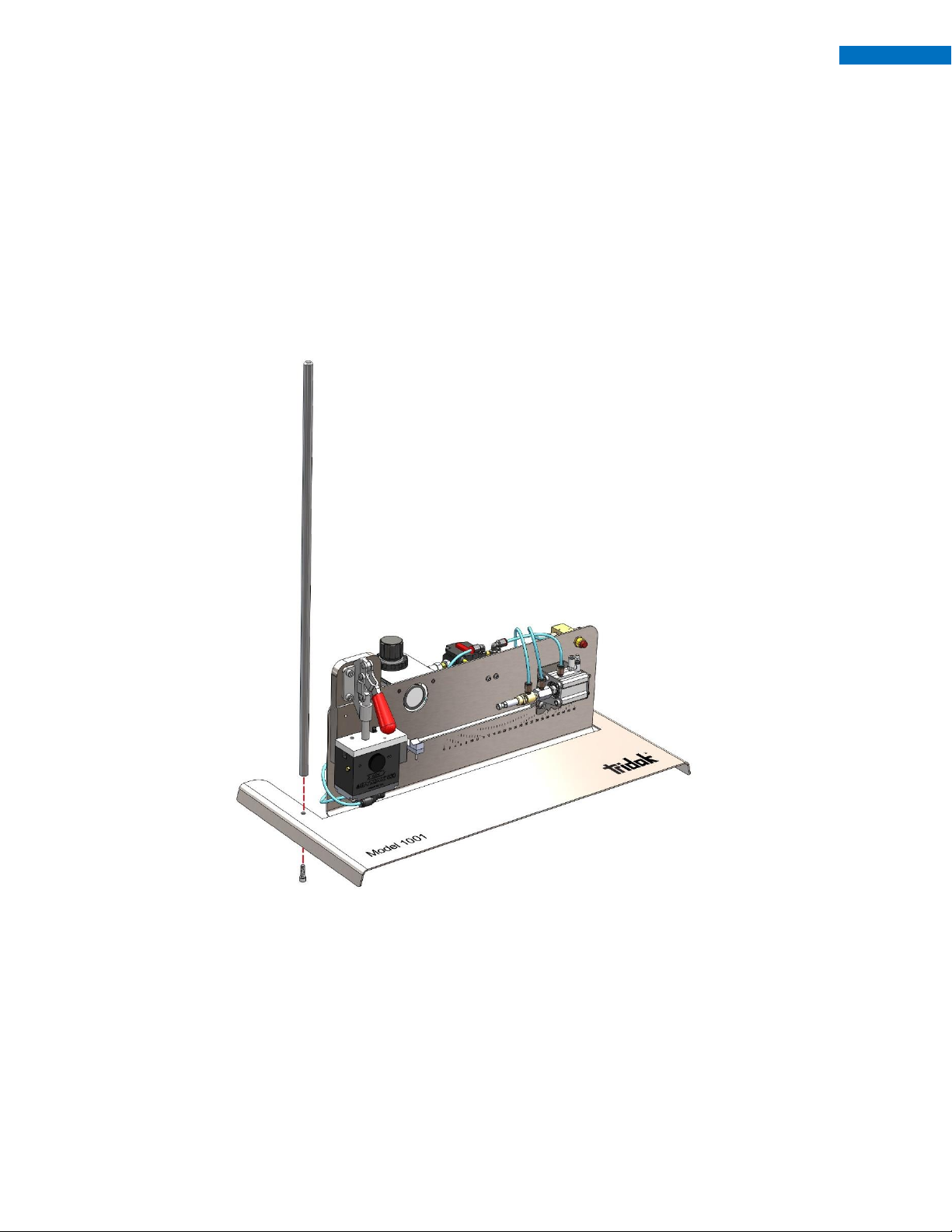
Installing the Reservoir Support ...................................................................................................................................... 9
Installing the Material Reservoir ..................................................................................................................................... 9
Connecting the Material Reservoir Pressure Supply Tube ............................................................................................ 10
Operation ..................................................................................................................................................... 10
Preparing the Cartridge................................................................................................................................................. 11
Loading the System ....................................................................................................................................................... 12
Pressurizing the System................................................................................................................................................. 14
Depressurizing the System ............................................................................................................................................ 15
Adjusting the Syringe Rest............................................................................................................................................. 15
Setting the Fill Amount for the Syringe Size .................................................................................................................. 15
Priming the System........................................................................................................................................................ 16
Preparing the Syringes................................................................................................................................................... 16
Filling the Syringe .......................................................................................................................................................... 17
Model 830 Valve Adjustments ...................................................................................................................................... 17
Cleaning and Maintenance ........................................................................................................................... 18
System Cleaning ............................................................................................................................................................ 18
Spare Parts and Accessories.......................................................................................................................... 18
Replacement Parts/Accessories ........................................................................................Error! Bookmark not defined.
Specifications................................................................................................................................................19
System Specifications .................................................................................................................................................... 19
Index....................................................................................................................Error! Bookmark not defined.

4
Tridak® Model 1001 Syringe Filling System User Guide
Introduction
Introduction to the User Guide
This guide describes how to assemble, use, and maintain the Model 1001 Syringe Filling System safely and
efficiently.
Intended Audience
We prepared this user guide for experienced process engineers, technicians, and manufacturing personnel. If
you are new to filling systems and do not understand the instructions, contact Dymax Application Engineering
to answer your questions before using the equipment.
Where to Get Help
Additional resources are available to ensure a trouble-free experience with our products:
■Detailed product information on www.tridak.com
■Customer Support and Engineering teams are available in the United States, Monday through Friday,
from 8:00 a.m. to 5:30 p.m. Eastern Standard Time. You can also email us at [email protected]. Please
see the back cover of this user guide for worldwide contact information.
Safety
WARNING! If you use this filling system without first reading and understanding the
information in this user guide, injury can result. To reduce the risk of injury, read and ensure you
understand the information in this user guide before assembling and operating a Tridak filling
system.
General Safety Considerations
All users of Tridak equipment should read and understand this user guide before assembling and using the
equipment.
Specific Safety Considerations
Using Safe Operating Pressures
Pressurizing the components in the dispensing system beyond the maximum recommended pressure can
result in the rupturing of components and serious personal injury. To minimize the risk of rupturing
components and injury, do not exceed the maximum operating pressure of the components in your filling
system.

5
Tridak® Model 1001 Syringe Filling System User Guide
Preventing Injection Injury
Discharging fluids or compressed air with a dispensing tip against your skin can cause very serious injection
injury. To minimize the risk of injection injury, do not place the dispensing tip in contact with your skin.
Personal Protective Equipment
Operators are recommended to wear any personal protective equipment specified by their company’s safety
policy for the materials used during filling. Personal protective equipment should be in place and used at all
times before pressurizing the system and when handling any potentially hazardous materials.
Product Overview
Description of the Model 1001 Syringe Filling System
The Model 1001 Syringe Filling System is designed to quickly fill piston and/or plunger-style syringes, one at a
time, quickly and accurately from a material reservoir. The system can be used with several different material
reservoirs including cartridge reservoirs, bottle reservoirs, and pail reservoirs. The system utilizes a Model 830
Disposable Fluid Path Valve to make material changeover fast and easy, while eliminating most cross-
contamination. The disposable fluid path can be fitted with a series of adapters to fill Luer-Lock and Oral tip
syringe types.
Special Features and Benefits of the Model 1001
This machine features several design features to make filling simple, quick and clean, including:
▪Disposable fluid path valve with disposable wetted parts that eliminate material contamination and
minimize clean-up and maintenance
▪Disposable fluid path can be capped and remain attached to the material cartridge for storage
▪Adjustable suck-back feature allows for a clean dispense of stringy and tacky materials
▪Material reservoir pressure regulator to control the reservoir pressure used for filling
▪Fills various syringes including 0.5, 1, 3 and 5 ml (up to 60 ml) syringes with pre-inserted plunger;
tooling nozzles are available for both Luer-Lock or Oral tips.
▪Adjustable pneumatic stop assures accurate fills and provides automatic shut-off
▪Foot-switch for hands-free, one-touch, fill cycle activation
▪Quick clamp design for fast and easy material changeover
▪Small footprint; dimensions (L x W x H) –24 in x 12 in x 26 in (60.96 cm x 30.48 cm x 66.04 cm)

6
Tridak® Model 1001 Syringe Filling System User Guide
Description of Main Components
The main components in the Model 1001 Syringe Filling System include:
1. Air Regulator –The air regulator enables precise control of the air pressure in the fluid reservoir. The
air precision regulator includes:
a. Pressure gauge that displays the pressure in the fluid reservoir. A 0- to 100-psi (0- to
6.9-bar) pressure gauge is installed on the air regulator.
b. Pressure control knob that enables adjustment of the pressure of the air entering the
reservoir. 5-60 psi recommended for most applications.
2. Compressed Air Line –The air line consists of blue polyurethane tubing designed for compressed air
use.
3. Model 830 Valve –A disposable fluid path valve used to dispense material from the material
reservoir. This valve features suck-back, allowing drip-free dispensing from fill-to-fill.
4. Disposable Fluid Path –The fill tube and fittings used to deliver fluid material from bulk cartridges
to syringes. It is constructed of black, light-blocking polyethylene tubing compatible with many types
of commercial and medical fluids.
5. Material Reservoir Retainer –The reservoir retainers and tanks hold fluid reservoirs. Reservoir
retainers accept cartridge reservoirs. Reservoir tanks accept bottle and pail reservoirs.
6. Material Reservoir Support –The adjustable vertical support is used to mount material reservoir
support.
7. Material Reservoir Pressure Supply –The air supply line that pressurizes the material in the
material reservoir retainer. The air regulator controls the pressure supplied to the material reservoir.
8. Foot Switch –Depression of the foot switch initiates the machine fill cycle. Once the foot switch is
depressed, the machine will automatically cycle and shut off once the fill switch is tripped.
9. Adjustable Syringe Support –The support is used to ensure the syringe is supported to remain in
line with the fill stop switch and the Luer or Oral tip fitting.
10. Fill Stop –The air-operated switch that controls the machine shut off once target fill volume is
achieved.
11. Cylinder Retract Switch –Manual retraction switch for fill stop cylinder. This switch can be used to
stop the machine operation at any time in the cycle.
12. Quick Clamp Release –The clamp mechanism is used to hold the material line in the Model 830
Valve. The clamp allows for quick and easy material line changeover.

7
Tridak® Model 1001 Syringe Filling System User Guide
Figure 1. Main Components of the Model 1001 Syringe Filling System
Material Reservoir Retainer
Material Reservoir Support
Model 830 Valve
Quick Clamp Release
Fill Stop
Foot Switch
Compressed Air Line
Inlet (60-90 psi)
Air Regulator
Disposable Fluid Path
Cylinder Retract Switch
Adjustable Syringe Support
Material Reservoir Pressure Supply

8
Tridak® Model 1001 Syringe Filling System User Guide
Assembly and Setup
Unpacking and Inspecting Your Shipment
When your system arrives, inspect the boxes for damage and notify the shipper of box damage immediately.
Open each box and check for equipment damage. If parts are damaged, notify the shipper and submit a claim
for the damaged parts. Contact Dymax so that new parts can be shipped to you immediately.
The parts listed below will be included in your shipment. If parts are missing, contact your local Dymax
representative or Dymax Customer Support to resolve the problem.
Parts Included in the Model 1001 Syringe Filling System
▪Model 1001 with Foot Switch [1]
▪Tube Assemblies –Luer Female [2]
▪Reservoir [3]
▪Rod Assembly [4]
▪Airline Kit for Reservoir and Model 1001 [5 & 6]
▪Allen Key Kit [7]
▪0.32" Bleed Wire with Pull Ring [8]
▪Model 1001 User Manual [9]
▪Stopper Pin (for use with plunger-less syringes) [Not Shown]
Figure 2. Unpacking Diagram
Utilities Required
AIR: Clean, dry, non-lubricated air operating pressure of 60 –90 psi

9
Tridak® Model 1001 Syringe Filling System User Guide
Preparing the System for Use
Installing the Reservoir Support
1. Place the Reservoir Support on top of the screw hole in the left side of the system base.
2. Using the screw and washer provided, place screw with the washer through hole in base and attach
to Reservoir Support. Tighten the screw until the Reservoir Support is secure (Figure 3).
Figure 3. Reservoir Support Installation
Installing the Material Reservoir
1. Slide the Material Reservoir Retainer (Figure 4, D) over the top of the Reservoir Support (Figure 4, B).
2. Position the Material Reservoir Retainer on the Reservoir Support so that the bottom of the Retainer
is approximately 2 inches above the top of the Back Plate.
3. Using the Height Adjustment Handle (Figure 4, C) tighten the Set Screw until the Material Reservoir
Retainer does not move.

10
Tridak® Model 1001 Syringe Filling System User Guide
Connecting the Material Reservoir Pressure Supply Tube
1. Connect the material reservoir’s Pressure Supply (Figure 4, F) to the Air Regulator (Figure 4, G).
2. Connect the opposite end of the Material Reservoir Pressure Supply to the Material Reservoir Air Inlet.
NOTE: DO NOT CONNECT AIR TO COMPRESSED AIR LINE INLET (FIGURE 4, H) AT THIS TIME.
Figure 4. Syringe Filler with 20 oz Cartridge Retainer (Rear View)
C –Height Adjustment Handle
A –Material Reservoir Air Inlet
D –Material Reservoir
Retainer
E –Disposable Fluid Path
F –Material Reservoir Pressure Supply
G –Air Regulator
H –Compressed Air Line Inlet
(60-90 psi)
B –Material Reservoir Support

11
Tridak® Model 1001 Syringe Filling System User Guide
Operation
Preparing the Cartridge
1. Place pre-packaged, sealed Cartridge upright on a flat, stable working surface (Figure 5).
2. With the Nozzle up, remove the Colored Cap, and quickly insert the Mating Fitting from the
Disposable Fluid Path (Figure 6). Tighten firmly.
3. Ensure the Fluid Path is sealed with a Luer Fitting and Cap before transporting or loading the
Cartridge into the Reservoir Retainer.
NOTE: Low-viscosity fluids may require Teflon® wrap on threads.
Figure 5. Cartridge with Cap Installed
Figure 6. Cartridge with Fluid Path Installed
Nozzle
Remove Cap

12
Tridak® Model 1001 Syringe Filling System User Guide
Loading the System
Filling Material Reservoir
1. Remove the Reservoir Retainer Cover by removing the Star Nuts and Cover. Ensure the Retainer is
free and clear of any previously placed cartridges or packaging.
2. Insert the Cartridge/Fluid Path Assembly into the Reservoir Retainer.
3. Guide the Fluid Path downward, passing through the bottom of the Reservoir.
4. Press the Cartridge firmly into place until seated.
5. Replace the Reservoir Retainer Cover and tighten evenly and securely with Star Nuts until the Cover
forms a solid seal around the Cartridge.
If you experience any trouble, please contact Dymax Customer Service.
Figure 7. Material Reservoir Exploded Diagram
Star Nut
Star Nut
Cover
O-Ring
Cartridge
Cartridge Retainer
Fluid Path
Cartridge Mating Fitting

13
Tridak® Model 1001 Syringe Filling System User Guide
Installing the Fluid Path
1. Open quick clamp by lifting handle upward to open position.
2. Position the Fluid Path in the Luer Block Clamp so that the outer edge of the Luer Block Clamp just
catches the Luer Tip.
3. Close quick clamp by lowering handle downward to closed and locked position.
4. Ensure tubing remains centered in Model 830 Valve during clamping.
Figure 8. Luer Block Clamp
Luer Block Clamp
Luer Tip

14
Tridak® Model 1001 Syringe Filling System User Guide
Figure 9. Fluid Path Installation
NOTE: Follow the same assembly and replacement for the following filling configurations:
T15225
TUBE ASSEMBLY, LUER FEMALE
Pressurizing the System
NOTE: Before operating the machine at the beginning of each run, check that all tubes, covers, guards, and
safety devices are properly installed for operation.
The system is energized when a compressed air supply is connected to the System Pressure Inlet.
WARNING! Do not exceed 90 psi system pressure.
The following steps must be completed in order to safely pressurize the system. If these steps are not followed
correctly, it is possible to create a situation that could result in a material spill through the Luer Tip.
1. Ensure that the Fluid Path is correctly installed in the Luer Support and the Tube Support.
2. Check that the Luer Clamp and the Tube Support are clamped fully.
Fluid Path / Tubing
Valve Body
Tube Support
Over-Pinch Adjust
ASSEMBLED VIEW
Suck-Back Adjust
EXPLODED VIEW

15
Tridak® Model 1001 Syringe Filling System User Guide
3. Ensure the Luer Tip Cap is installed and tightened onto the Luer Tip.
4. Disconnect the Material Reservoir Pressure Supply from the Material Reservoir Air Inlet.
5. Connect a Compressed Air Supply (max 90 psi) to the System Pressure Inlet.
6. Set the Air Regulator to 0 psi.
7. Connect the Material Reservoir Pressure Supply to the Material Reservoir Air Inlet.
8. Set the Air Regulator to 10 psi starting pressure.
9. Check for any material leaks occurring at the Luer Tip or at the Material Cartridge and depressurize
the system if any leaks are present.
Depressurizing the System
1. Ensure the Luer Tip Cap is installed and tightened onto the Luer Tip.
2. Set the Air Regulator to 0 psi.
3. Disconnect the Material Reservoir Pressure Supply from the Material Reservoir Air Inlet.
4. Disconnect the Compressed Air Supply from the System Pressure Inlet.
Adjusting the Syringe Rest
Use the adjustable syringe rest to support the syringe during the fill cycle, and ensure the syringe is centered
around the fill stop switch. (Figure 10)
1. Slightly loosen the Syringe Rest Base Screw.
2. Slide the Syringe Rest Base along the fixture base slot channel until the Syringe Rest is close to the
syringe flange.
3. Tighten the Syringe Base Screw.
4. Loosen the Syringe Rest Set Screw.
5. Lift the Syringe Rest until the v-block is fully supporting the syringe.
6. Tighten the Syringe Rest Set Screw.
Setting the Fill Amount for the Syringe Size
For the required syringe size, use the scale to set the fill volume by adjusting the syringe fill stop to the desired
location.
1. Disconnect the Compressed Air Supply from the Material Reservoir.
2. Connect the incoming Air Supply Line to the Compressed Airline Inlet.
3. By hand, set the Syringe Piston or Plunger to the desired fill/mL volume.

16
Tridak® Model 1001 Syringe Filling System User Guide
4. Twist or slide the Syringe and Piston or extended Plunger on to the Nozzle/Needle/Luer-Lock Tip of
the Fluid Path.
5. Loosen the Syringe Fill Adjustment Lock by loosening the bottom two Allen Cap Screws (Figure 10).
6. Press and release the Foot Switch to extend the fill stop cylinder.
7. Move the Syringe Fill Stop to the position where it immediately touches the extended Syringe Plunger
or Syringe Piston.
8. Re-tighten the Syringe Fill Stop using Allen Cap Screws.
9. Press the Cylinder Retract switch to reset the system.
10. Connect the Compressed Air Supply from the Material Reservoir.
Figure 10. Model 1001 with Syringe Inserted
Priming the System
During initial setup and when changing material cartridge reservoirs, air must be purged from the disposable
fluid path/fill tube to prevent accidental spills and introducing bubbles into syringes. Prime the system by
running material through the fluid path until a constant, solid flow of material is achieved. Depending on
material, reducing the pressure by 5-15 psi will make it easier to see the air being purged.
Preparing the Syringes
Before filling each syringe, ensure the syringe plunger is fully inserted to the tip of the syringe to remove most
of the air from the empty syringe.
Allen Cap Screws
Syringe
Fill Stop
Syringe
Syringe
Piston
Luer Tip
Syringe
Plunger
Syringe
Rest
Syringe Rest
Set Screw
Syringe Rest
Base Screw
Syringe Rest
Base

17
Tridak® Model 1001 Syringe Filling System User Guide
Filling the Syringe
1. Remove the Cap from the Luer Tip.
2. Load the required Syringe size by threading it onto the Luer Tip (Figure 10).
3. Make sure all hands and fingers are clear of the machine. Press and release the Foot Switch to
activate the filling cycle.
4. The system will automatically shut off when the Syringe Piston or Syringe Plunger touches the Syringe
Fill Stop.
NOTE: Use the Cylinder Retract Switch as an E-Stop if the machine does not stop automatically.
5. Remove the Syringe from the Luer Tip.
6. Cap the Syringe Tip and the Syringe End as needed.
7. Repeat above steps 2 through 6 for each additional syringe needed.
Model 830 Valve Adjustments
The Model 830 Valve highlights a suck-back feature to prevent oozing and dripping between syringes.
Depending on the type of fluids used, the suck-back feature will require adjustment. Batch-to-batch
adjustment is recommended. If material drips, suck-back should be increased. If there are air bubbles in the
syringe, decrease the amount of suck-back.
Adjusting Suck-Back Position (Front)
The Adjustment Screw is located on the top face of the valve. To increase suck-back, loosen the adjustment
screw counter-clockwise. To decrease suck-back, tighten the adjustment screw clockwise (
Figure 11).
Figure 11. Suck-Back Adjustment Screw
Increase Suck-Back (Counter-Clockwise)
Decrease Suck-Back (Clockwise)
Increase Suck-Back (Counter-Clockwise)
Decrease Suck-Back (Clockwise)

18
Tridak® Model 1001 Syringe Filling System User Guide
Cleaning and Maintenance
System Cleaning
Switching to a Different Material
The disposable fluid path in the Model 830 Valve allows for quick and easy material changeover. To switch
your system over from dispensing one material to dispensing a new material, simply replace the fluid path
tube in the dispensing valve. You will also need to replace the material reservoir on the system. The new
material can be placed in a new material reservoir or the existing reservoir can be cleaned, and the material
replaced.
Spare Parts and Accessories
Part Number
Item
Air Lines & Regulators
T16789
Air Supply Line
T18297
Material Regulator Replacement Kit
Reservoir Cartridge Kits
T15223
20 oz Cartridge Reservoir
T15224
32 oz Cartridge Reservoir
T15224
1 Gallon Reservoir
Low-Level Sensing Kits
T17970
20 oz Low Level Reservoir
T17922
32 oz Low Level Reservoir
T17985
1 Gallon Low Level Reservoir
Model 830 Parts
T18196
Model 830 Valve
T18550
Model 830 Valve Rebuild Kit
Tube Assemblies
T15225
Tube Assembly, Luer Female
T18305
Tube Assembly, No Tip (For Use with Custom Tooling)
Misc.
T18218
Bleed Wire with Pull Ring
T16603
Pneumatic Foot Switch
T17990
Nut Back Plate
T114230
Nut Back Plate Screw

19
Tridak® Model 1001 Syringe Filling System User Guide
Specifications
Materials of Construction—Wetted Parts
▪Dispensing valve = no wetted parts
■Fluid tubing = light blocking, black, polyethylene
▪Fluid cartridge reservoirs = HPDPE
■Fluid cartridge reservoir piston = HDPE
■Fluid tubing fittings = acetal
Operating Specifications
Recommended compressed air supply pressure to air filter/regulator = 60 psi min (4.1 bar)
Maximum pressure setting at air filter/regulator = 100 psi (6.9 bar)
Compatible material viscosity range: 1 –60,000 cP
Reservoir Retainer/Tank Sizes
Cartridge retainers hold 20 and 32-oz (550 and 900-mL) reservoirs
1-gallon (3.8 L) jug and 5-gallon (15L) pail drop in reservoir options available: inquire with Dymax Customer
Service
Air Regulator Pressure Gauges
Pressure gauge installed from factory = 0 to 100 psi (0 to 6.9 bar)
Dimensions
Dimensions (L x W x H) –24 in x 12 in x 25 in (60.96 cm x 30.48 cm x 66.04 cm)
Figure 12. Model 1001 Syringe Filling System Dimensions

© 2019 Dymax Corporation. All rights reserved. All trademarks in this guide, except where noted, are the property of, or used under license by Dymax Corporation, U.S.A.
Please note that most filling and repackaging system applications are unique. Dymax does not warrant the fitness of the product for the intended application. Any warranty applicable to the product, its application and use is strictly limited
to that contained in Dymax’s standard Conditions of Sale. Dymax recommends that any intended application be evaluated and tested by the user to insure that desired performance criteria are satisfied. Dymax is willing to assist users in their
performance testing and evaluation. Data sheets are available for pressure pots upon request. T18762 MAN096 5/2/2019
Dymax Oligomers & Coatings
Dymax Asia (H.K.) Limited
Dymax UV Adhesives & Equipment (Shanghai) Co. Ltd.
Dymax Asia Pacific Pte. Ltd.
Dymax Engineering Adhesives Ireland Ltd.
Dymax UV Adhesives & Equipment (Shenzhen) Co. Ltd.
Dymax Korea LLC
Table of contents
Other dymax Industrial Equipment manuals

dymax
dymax BlueWave 200 Programming manual

dymax
dymax 39380 User manual

dymax
dymax BlueWave 200 User manual

dymax
dymax BlueWave AX-550 Programming manual

dymax
dymax BlueWave FX-1250 User manual

dymax
dymax BlueWave MX-150 User manual

dymax
dymax T40571 User manual

dymax
dymax BlueWave AX-550 User manual

dymax
dymax ZIP User manual

dymax
dymax BlueWave 200 User manual
Popular Industrial Equipment manuals by other brands

M&R
M&R CHALLENGER II Series manual

Newport
Newport FMS Series user manual

MKS
MKS HPS 919 Series Operation and maintenance manual

Judo
Judo FERROCLEAN Installation and operating instructions

Fels
Fels Mobilis ELITE Assembly instructions

Zehnder Rittling
Zehnder Rittling ComfoPost Installation and maintenance manual