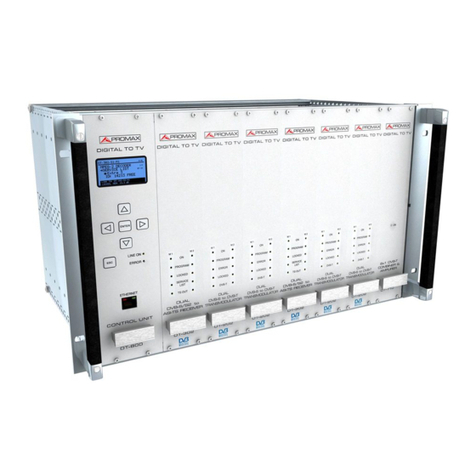
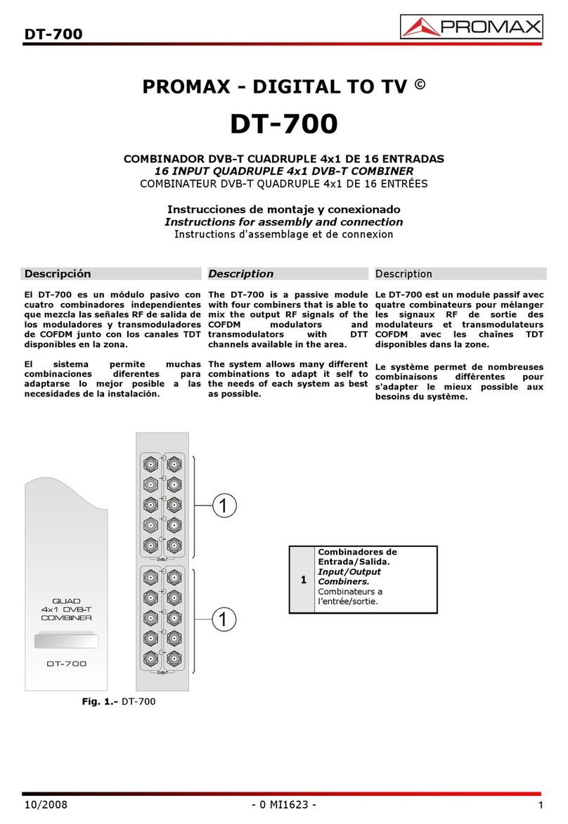
Promax DT-802 User manual

SAFETY NOTES
Read the instruction manual before using the equipment, mainly "SAFETY
RULES" paragraph.
The symbol on the equipment means "SEE USER’S MANUAL". In this manual
may also appear as a Caution or Warning symbol.
Warning and Caution statements may appear in this manual to avoid injury
hazard or damage to this product or other property.

English
CONTROL MODULE. DT-802
TABLE OF CONTENTS
1. GENERAL..................................................................................................................1
1.1 Description ..........................................................................................................1
1.2 Specifications......................................................................................................2
2. SAFETY RULES........................................................................................................5
2.1 General................................................................................................................5
2.2 Descriptive Examples of Over-Voltage Categories.............................................6
3. INSTALLATION .........................................................................................................7
3.1 DT-900 Sub-rack.................................................................................................7
3.2 Instalación de los módulos en el DT-900............................................................9
3.3 Connecting wires.................................................................................................9
3.4 Instruccions for installation................................................................................12
4. INSTRUCTIONS FOR USE.....................................................................................13
4.1 Description of the Controls and Elements.........................................................13
4.2 Arrows and Function Keys Description .............................................................14
4.3 LEDs Table........................................................................................................15
4.4 DT-802 Starting Up ...........................................................................................15
4.5 Main Screen......................................................................................................16
4.6 PASSWORD .....................................................................................................18
4.7 CONFIGURATION............................................................................................19
4.7.1 Description of the initial setup screen.........................................................19
4.7.2 Browsing the SETUP menu........................................................................20
4.7.3 Entering, Editing and Selecting values .......................................................21
4.7.4 DT-802 Configuration..................................................................................22
4.8.2 PkUpdate....................................................................................................27
5. PRACTICAL EXAMPLES OF SYSTEMS DTTV .....................................................29
6. GLOSSARY OF TERMS .........................................................................................33
7. MAINTENANCE.......................................................................................................37
7.1 Cleaning Recommendations.............................................................................37

CONTROL MODULE. DT-802

English
CONTROL MODULE. DT-802
04-2015 Page 1
CONTROL MODULE
DT-802
DIGITAL TV HEADEND
1. GENERAL
1.1 Description
The DTTV system (Digital to TV) is based on a TV headend that receives television
signals from different sources. It processes them for its integration into an output signal in
Digital Terrestrial (DVB-T) format. In this way, the signal can be distributed on a TV
network with multiple receivers, keeping the original wiring installation but distributing in
high-quality format. This system is applicable to hotels, hospitals, shopping centres,
universities, etc. that is, local distribution networks that want to distribute media content in
digital quality.
The DT-802 is the control and power module, therefore is the most important
module of the DTTV system. The control module is connected to all the modules of the
headend via modem-cable.
The DT-802 allows controlling and configurating each module individually. The user
can manage and check the status of any module in two different ways: in local mode or in
remote mode. In local mode, the module is managed via the keypad and the LCD screen
placed on the frontal of the DT-802. In remote mode, the control module is connected to a
computer through a network cable and it is managed by using the specific software
control.
The difference between the control module DT-800 and the control module
DT-802 is that the DT-802 has a redundant power system based on two totally
independent batteries that can be hot-swapped without affecting the network distribution
system. The redundant battery works when the other battery fails due to a malfunction
or a failure of the supplier. It warns the user using a buzzer and a light.

CONTROL MODULE. DT-802
1.2 Specifications
MODULE
Control/Supply Up to 7 modules DT-802.
Auto-config Auto-detection of connected modules.
Auto-link Auto-detection of interconnection between
modules.
Local interface LCD screen.
Navigation keypad (6 keys).
3x information LEDs: On / Not ready / PSU
Status.
Intuitive Navigation Menu (tree type menu).
COMMUNICATIONS
Ethernet 10/100Mb. Via virtual serial port.
MODULES CONFIGURATION
Local Through local interface.
Remote Through Ethernet port (PC software supplied).
POWER SUPPLY
Network voltage 90 — 250 V AC
Network frequency 50-60 Hz.
Consumption 6 A / 3 A maximum for a range lower / higher at
the input voltage.
Output Connector JST B08P-XL-HDS.
Amount 4
Output voltage + 12 V, 14 A max.
+5 V, 20 A max.
OPERATING ENVIRONMENTAL CONDITIONS
Altitude Up to 2000 m.
Temperature range From 5 °C to 40 °C.
Max. Relative humidity 80 % ( 31 °C), decreasing lineally up to 50% to
40 °C.
MECHANICAL FEATURES
Dimensions W. 50 x H. 262 x D. 230 mm.
Weight 1.85 kg.
Page 2 04-2015

English
CONTROL MODULE. DT-802
04-2015 Page 3
ACCESORIES SUPPLIED
2 x CC005 Mains cord.
1 x CC043 Cable Alim. 3 mod.
1 x CC044 Cable Alim. 4 mod.
1 x CC143 Cable Alim. 350 mm 4 mod (DT-802).
1 x CC144 Cable Alim. 470 mm 4 mod (DT-802).
1 x 0 MI1786 User’s Manual DT-802.
SPARE PARTS
AL-802 1 x Spare Power Supply.
(each control unit DT-802 integrates two sources
AL-802).
RECOMMENDATIONS ABOUT THE PACKING
It is recommended to keep all the packing material in order to return the
equipment, if necessary, to the Technical Service.

CONTROL MODULE. DT-802
Page 4 04-2015

English
CONTROL MODULE. DT-802
04-2015 Page 5
2. SAFETY RULES
2.1 General
* The safety could not be assured if the instructions for use are not closely
followed.
* Use this equipment connected only to systems with their negative of
measurement connected to ground potential or isolated from the network.
* This is a Class I equipment, for safety reasons plug it to a supply line with the
corresponding ground terminal.
* This equipment can be used in Overvoltage Category II installations and
Pollution Degree 1 environments.
* When using some of the following accessories use only the specified ones to
ensure safety.
Power cord.
* Observe all specified ratings of supply.
* Remember that voltages higher than 70 V DC or 33 V AC rms are dangerous.
* Use this instrument under the specified environmental conditions.
* The user is not allowed to perform changes inside the equipment. Any change
on the equipment must be done exclusively by specialized staff.
* When using the power adaptor, the negative of signal is at ground potential.
* Do not obstruct the ventilation system of the instrument.
* Use appropriate low-level radiation cables for Input / output signals, especially
on high level signals.
* Use remote configuration cables <3m.
* Follow the cleaning instructions described in the Maintenance paragraph.

CONTROL MODULE. DT-802
* Symbols related with safety:
2.2 Descriptive Examples of Over-Voltage Categories
Cat I Low voltage installations isolated from the mains.
Cat II Portable domestic installations.
Cat III Fixed domestic installations.
Cat IV Industrial installations.
Page 6 04-2015

English
CONTROL MODULE. DT-802
04-2015 Page 7
3. INSTALLATION
3.1 DT-900 Sub-rack
The DT-900 is a metallic casing (sub-rack), where the DTTV modules are
installed (Fig. 1).
Supplied accessories allow the subrack to be set up in two ways: Installing it in a
19 " rack cabinet (Fig. 2) or anchoring it on a wall.
The wall anchoring system allows, through a tilting system, accessing the rear of
the subrack, where the connectors are placed (Fig. 3).
One subrack can contain approximately 8 modules. One of them must be the
control module DT-802.
The sub-rack DT-900 is supplied with an user’s manual, which describes in detail
the steps to complete the assembly.
Figure 1.- Subrack Assembly DT-900.

CONTROL MODULE. DT-802
Figure 2.- Assembling a DT-900 in a Rack Cabinet.
Figure 3.- Tilting System.
Page 8 04-2015

English
CONTROL MODULE. DT-802
04-2015 Page 9
3.2 Installing modules in the DT-900.
To install a module in the subrack, you should slide the module into the subrack,
screwing it to the frontal guide (Fig. 4).
In order to get a tidy installation of the modules you should follow the next
advises:
•Place the DT-802 at the left end of the sub-rack.
•Place the DT-700 and / or DT-710 at the right end of the sub-rack.
•Place the DT-101/102 and the DT-301/302 side by side in the case they were
paired.
•Place the rest of the modules together, without leaving a gap between them.
Figure 4.- Installation of the modules into the sub-rack.
Following these advises you will achieve a tidy installation and the best
configuration for later maintenance or new modules addition.
3.3 Connecting wires
The modular composition of the DTTV headend makes it flexible to adapt it to
customer needs.

CONTROL MODULE. DT-802
The DT-802 module has two IEC C14 inlet connector to power directly from the
mains. The DT-802 has four power outputs for the control and power of the rest of
modules. They work equally and can be used for any module. Along with the DT-802
module are supplied the control and power cables.
It does not exist a standard configuration for a DTTV headend. Depending on the
use you want for it, the configuration and position of the modules would change, and
therefore it will change the connection between them. Each module is supplied with
interconnecting cables, which are needed to carry out any possible combination
between modules.
Figure 5.- Application example DTTV.
The wiring must be done when the DT-802 module is off. You do not have to turn
it on until ALL connecting work is done (on one hand control cables between the CPU
and the modules and on the other hand, TS cables between modules). This is because
during the starting up, the CPU scans all the modules, in order to determine the relation
among them. If you turn it on before connecting, you will have to spend additional time
defining the links by hand because the CPU can not detect the connections made in
real time.
Page 10 04-2015

English
CONTROL MODULE. DT-802
04-2015 Page 11
If you change connection cables between modulators and receivers, you should
reboot the system so that the CPU will do a new assignment, otherwise you will should
modify assignments manually using the setup menu of the DT-802 module.
If there is any pair of DT-101/102 and DT-301/302 linked, NO place each one in a
different sub-rack controlled by different control modules because it would not work
properly.
Figure 6.- Application example DTTV.
The DT-802 has an electric current sensor that prevents it from starting up when it
is not connected to any module. Therefore the control module will not be ON if at least
one connection is made previously.
The combiner modules DT-700 and DT-710 are supplied with some resistors to
balance the inputs/outputs not used and unbalanced. You should also bear in mind that
the module DT-802 does not control these two modules. The DT-700 is also a passive
module combiner that does not need to be powered.
The necessary devices to connect the antenna or signal sources to the headend
(Splitters, cables, connectors, etc.) are not supplied with the DTTV. In the same way, if
you want to combine an output DTTV signal with other signals already existing, such as
DTT, the installer will must provide the necessary connectors.

CONTROL MODULE. DT-802
For an optimal use of the capabilities of the DTTV, it is advisable to use an
universal LNB with independent outputs or an universal LNB with dual polarity (V/H)
and dual band (L/H), both with a switchable splitter for satellite, in order to be able of
distributing simultaneously signals in different bands and polarisations.
It is not advisable to use an universal LNB with only one output and a satellite
splitter because in that case all the modules would be tuned at the same polarisation
(V or H) and band ( L or H).
3.4 Instructions for installation
After identifying the elements that make up a DTTV installation, now we are going
to explain the basic procedure for installing and starting-up:
1. Assemble the DT-900 subrack. Follow the assembling steps described on the
manual supplied with the sub-rack.
2. Depending on your needs and available space, put the subrack on a wall or inside
a rack cabinet.
3. Install the modules inside the subrack and their connecting wires. Follow the
specific instructions provided with each module.
4. Before running the headend you should check that you are receiving input signals
properly (satellite TV, analogue, etc...).
5. Check that all modules are wired properly, especially the power cord from the
control module to the modules and the wiring between them.
6. Start up the system using the switches placed at the rear of your control module.
7. Wait for a few seconds until the control module finishes sweeping and detects all
the modules. After that, all them will receive the default configuration data.
8. Verify that the modules detected by the control module and appearing on the
screen correspond to the ones installed. Also, you should check there is not any
error message on the screen (Note: On one hand, the modules DT-700 and
DT-710 are not detected by the control module and on the other hand, dual
modules appear as two independent units).
9. Set up each module according to your needs.
10. If you have changed the configuration, you should save and restart the control
module in order to apply the changes on the modules.
11. At the end of the process all LEDs should be GREEN or off. If there is any LED in
RED, check the configuration and wiring of each module according to the error
description showed on the screen.
12. Connect the DTTV output to a receiver device, then tune the signal and check
you are receiving the TV programmes and services.
Page 12 04-2015

English
CONTROL MODULE. DT-802
04-2015 Page 13
4. INSTRUCTIONS FOR USE
4.1 Description of the Controls and Elements
The only element of control is the DT-802 module. The rest of modules refer to
their status by LEDs place on the front of the module.
Frontal Panel
Figure 7.- Panel frontal DT-802.
[1] Display.
[2] Control Keys.
[3] Escape Key.
[4] PSU (Power Supply Unit) status.
[5] Ethernet RJ-45 Connector.
[6] Buzz (Pulsar para apagar el zumbador).

CONTROL MODULE. DT-802
[7] Online LED.
[8] LED NOT READY.
[9] Power Connector (IEC C14).
[10]LED operating.
[11]Power Switch.
[12]LED Failure.
[13]RESET button
[14]Power and Control Output
4.2 Arrows and Function Keys Description
Figure 8.- Function Keys.
Enter the menu / Validate / Select / Deselect.
Go to the upper level menu / Increase a number.
Go to a lower level menu / Decrease a number.
Go to the menu on the right / Go to the number on the right.
Go to the menu on the left / Go to the number on the left.
Exit without validating.
Page 14 04-2015

English
CONTROL MODULE. DT-802
04-2015 Page 15
4.3 LEDs Table
The LEDs of each module indicate a certain status depending on the colour.
The LEDs are placed on the front panel of the module.
In the case of a dual module, there will be two columns of LEDs, one per each
module.
Name Status Description
GREEN The module is receiving voltage and working.
ON OFF Off / Does not work.
GREEN It is working properly.
ERROR RED There is an error in the process.
GREEN Transport Stream received correctly.
TS-IN RED There is a problem in the reception of the
Transport Stream (too fast, TS wrong...).
GREEN DVB-T output signal is correct.
DVB-T RED Problem at the output.
INTERMITTENT GREEN DT-802 is programming the unit.
PROGRAM OFF No programming.
GREEN Locked signal.
LOCKED RED It was not posible to tune.
GREEN Service List detected.
SERVICE LIST RED It was not able to read the service list.
GREEN Proper TS output.
TS-OUT RED Problems at the TS output.
GREEN Audio and video processing is working properly.
A/V RED Error during the process / Encoder broke down.
GREEN Proper Multiplexing.
MUX RED Error during multiplexig. / Multiplexer broke down.
Table 2.-Table of LEDs description.
4.4 DT-802 Starting Up
Turn on your equipment through the switch, which is placed on the rear panel of
the module ( Fig. 7 [11] ).
After starting up, the DT-802 scans the modules connected to it in order to detect
how many and what modules are and if there is any problem.
During the scan, the control module carries out the assignment of bus addresses
and after that an AUTOLINK, which consists in identifying those receivers / modulators
paired (eg DT-301/302 with DT-101/102). This function is essential for a proper
definition of the SERVICES LIST. In order to this assigment works, is necessary to
make the wire connections before starting up. Otherwise you will should made
assigments manually, with the consequent loss of time.

CONTROL MODULE. DT-802
The scanning process takes about ten seconds. After it, it displays on the screen
a list of all the modules identified. If the process takes longer, maybe there is a problem
with the wiring or the CPU.
4.5 Main Screen
The main screen shows the list of all the modules identified.
At the top of the screen the text MODULES FOUND indicates the number of
modules detected and below a list with the names of each one of the modules.
If the modules detected are more than four, the list is rotating, that is, it rotates on
a sequential order to show all the elements.
The modules are identified as follows:
DT-XXX-SY-MZ
Where:
XXX Indicates the name of the module.
SY Smeans SLOT and Yis a number equal to the slot position in the
subrack case. This position is the one the module assigns
automatically every time you turn it on. If it does not correspond to
the actual position can be changed manually, but it does not affect
the operation for practical purposes.
MZ Mmeans MODULE and Zis a number that identifies the receiver or
modulator module (1 for the first module, 2 for the second one).
The bottom of the screen shows the current STATUS of the modules. If
everything is correct it shows the message "OK. PRESS ENTER TO SETUP" (Fig. 9).
Figure 9.- Main Screen.
Page 16 04-2015
Table of contents
Other Promax Control Unit manuals
Popular Control Unit manuals by other brands

Detcon
Detcon 700 instruction manual

WIESHEU
WIESHEU Exclusive Original operating instructions

Danaher Motion
Danaher Motion Amplifier MDM-7 Operator's manual

Akytec
Akytec PRM-X.1 user guide

Fujitsu
Fujitsu UMTS Mounting instructions

Telit Wireless Solutions
Telit Wireless Solutions UE866-N3G Hardware user's guide