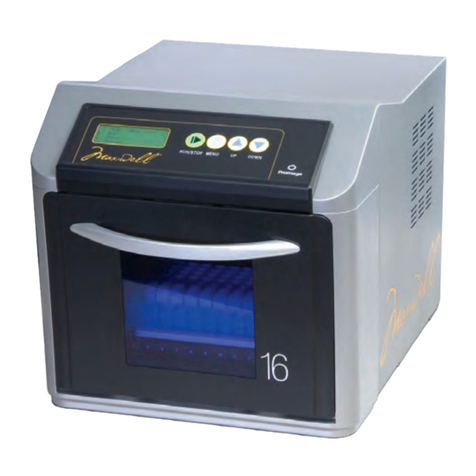
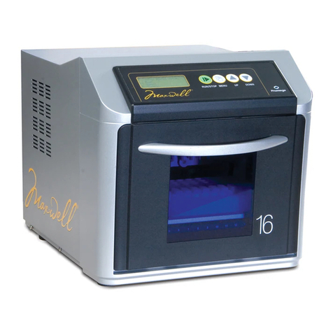
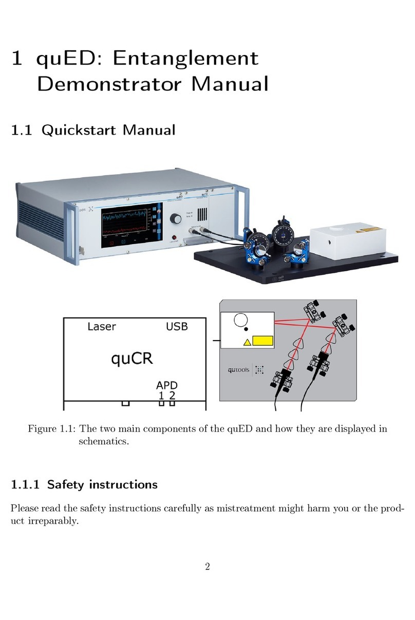
Promega Maxwell 16 AS1000 User manual

Technical Manual
Maxwell®16 Instrument
Operating Manual
INSTRUCTIONS FOR USE OF PRODUCTS AS1000 AND AS1002.
PRINTED IN USA. Revised 6/08 Part# TM274
Note: Please ensure that all sealing tape and any residual adhesive are removed from
the Maxwell®16 system cartridges before placing the cartridges into the instrument.
tm274.0608.qxp 6/4/2008 9:40 AM Page a

Promega Corporation · 2800 Woods Hollow Road ·Madison, WI 53711-5399 USA ·Toll Free in USA 800-356-9526 ·Phone 608-274-4330 ·Fax 608-277-2516 · www.promega.com
Printed in USA. Part# TM274
Revised 6/08 Page 1
I. Introduction...................................................................................................................................................................2
A. Maxwell®16 Instrument Specifications...........................................................................................................2
B. Product Components .........................................................................................................................................3
C. Inspection.............................................................................................................................................................4
D. Precautions...........................................................................................................................................................6
E. Environmental Requirements ...........................................................................................................................8
II. Hardware Overview.....................................................................................................................................................8
III. Setting Up the Maxwell®16 Instrument................................................................................................................10
A. Setup ...................................................................................................................................................................10
B. Removal of Magnetic Rod Assembly and Plunger Bar Shipping Anchors.............................................10
C. Reconfiguring the Maxwell®16 Instrument Hardware..............................................................................13
(i) Changing from Standard to LEV Configuration...................................................................................13
(ii) Changing from LEV to Standard Configuration...................................................................................15
D. Operational Mode Setup..................................................................................................................................16
(i) Setting the Maxwell®16 Instrument Operational Mode......................................................................18
(ii) Changing the Maxwell®16 Instrument Operational Mode.................................................................18
IV. Operating the Maxwell®16 Instrument.................................................................................................................20
A. Navigation .........................................................................................................................................................20
B. Operational Qualification................................................................................................................................20
C. Sample Purification .........................................................................................................................................21
V. Periodic Cleaning and Maintenance ......................................................................................................................22
A. General Care......................................................................................................................................................22
B. Removal of Magnetic Rod Assembly ............................................................................................................23
C. Periodic Maintenance.......................................................................................................................................23
VI. Troubleshooting .........................................................................................................................................................24
VII. Appendix......................................................................................................................................................................27
A. Updating Firmware..........................................................................................................................................27
B. Instrument Return ............................................................................................................................................27
C. Instrument Disposal .........................................................................................................................................30
D. Certificate of Decontamination.......................................................................................................................31
E. Warranty Information......................................................................................................................................32
F. Related Products...............................................................................................................................................33
EU Declaration of Conformity.................................................................................................................................35
All technical literature is available on the Internet at www.promega.com/tbs/
Please visit the web site to verify that you are using the most current version of this Technical Manual.
Please contact Promega Technical Services if you have questions on the use of this product. Email: [email protected]
Maxwell®16 Instrument Operating Manual
tm274.0608.qxp 6/4/2008 9:40 AM Page 1

I. Introduction
As laboratories try to improve productivity, the need has increased for easy-to-use, low- to moderate-
throughput automated purification processes. The Maxwell
®
16 Instrument
(a)
is designed for efficient,
automated purification from a wide range of sample types. The instrument is supplied with
preprogrammed automated purification methods and is designed for use with predispensed reagent
cartridges, maximizing simplicity and convenience. The instrument can process up to 16 samples in
approximately 15–40 minutes (depending on sample type and method). Purified concentrated products
are obtained at high quality and high yield and can be used directly in a variety of downstream
applications.
The Maxwell
®
16 Instrument can be configured for different sample elution volume preferences.
The Maxwell
®
16 LEV Instrument (Cat.# AS1002) is configured with low elution volume (LEV)
hardware settings, while the Maxwell
®
16 Instrument (Cat.# AS1000) is configured with standard
elution volume (SEV) hardware settings. Using the Maxwell
®
16 SEV Hardware Kit (Cat.# AS1200) or
the Maxwell
®
16 LEV Hardware Kit (Cat.# AS1250), the Maxwell
®
16 Instrument can be reconfigured
to accommodate either preference.
The Maxwell
®
16 System purifies samples using paramagnetic particles (PMPs), which provide a mobile
solid phase that optimizes capture, washing and elution of the target material. The Maxwell
®
16
Instrument is a magnetic-particle-handling instrument that efficiently preprocesses liquid and solid
samples, transports the PMPs through purification reagents in the pre-filled cartridges, and mixes
efficiently during processing. The efficient magnetic particle-based methodology used by the Maxwell
®
16
Instrument avoids common problems associated with automated purification systems, such as clogged tips
or partial reagent transfers, which can result in suboptimal purification. Several Maxwell
®
16 reagent kits
are available that allow optimal purification from a variety of sample types.
I.A. Maxwell
®
16 Instrument Specifications
Processing Time: 15–40 minutes (depending on sample type and method)
Number of Samples: up to 16
Standard Configuration: 300µl elution volume
LEV Configuration: 20–100µl elution volume
Weight: 40lb (18kg)
Dimensions (W × D × H): 12.4 × 14.7 × 11.6 inches (314 × 374 × 295mm)
Power Requirements: 100–240VAC, 50–60Hz, 2.1A
Promega Corporation · 2800 Woods Hollow Road ·Madison, WI 53711-5399 USA ·Toll Free in USA 800-356-9526 ·Phone 608-274-4330 ·Fax 608-277-2516 · www.promega.com
Part# TM274 Printed in USA.
Page 2 Revised 6/08
tm274.0608.qxp 6/4/2008 9:40 AM Page 2

Promega Corporation · 2800 Woods Hollow Road ·Madison, WI 53711-5399 USA ·Toll Free in USA 800-356-9526 ·Phone 608-274-4330 ·Fax 608-277-2516 · www.promega.com
Printed in USA. Part# TM274
Revised 6/08 Page 3
I.B. Product Components
Product Cat.#
Maxwell
®
16 Instrument AS1000
For Laboratory Use. Includes:
• 1 Standard Elution Volume Configuration Instrument
• 1 Power Cable
• 1 RS-232 Cable for Firmware Upgrades
• 1 1.5mm Hex Wrench
• 1 Maxwell
®
16 Cartridge Rack
• 1 Maxwell
®
16 Magnetic Elution Rack
• 1 Operating Manual and Warranty Information
• 1 Quick Start Guide
Product Cat.#
Maxwell
®
16 LEV Instrument AS1002
For Laboratory Use. Includes:
• 1 Low Elution Volume Configuration Instrument
• 1 Power Cable
• 1 RS-232 Cable for Firmware Upgrades
• 1 1.5mm Hex Wrench
• 1 Maxwell
®
16 LEV Cartridge Rack
• 1 Operating Manual and Warranty Information
• 1 Quick Start Guide
Available Separately
Product Cat.#
Maxwell
®
16 SEV Hardware Kit AS1200
Required to convert a Maxwell
®
16 LEV Instrument to a standard elution volume instrument. Includes:
• 1 Standard Magnetic Rod/Plunger Bar Assembly
• 1 Maxwell
®
16 Cartridge Rack
• 1 Maxwell
®
16 Magnetic Elution Rack
Product Cat.#
Maxwell
®
16 LEV Hardware Kit AS1250
Required to convert a standard Maxwell
®
16 Instrument to a low elution volume (LEV) instrument. Includes:
• 1 LEV Magnetic Rod Assembly
• 1 LEV Plunger Bar Adaptor
• 1 Maxwell
®
16 LEV Cartridge Rack
Product Cat.#
Maxwell
®
16 LEV Cartridge Rack (for use with LEV configuration) AS1251
Maxwell
®
16 Cartridge Rack (for use with standard configuration) AS1201
Maxwell
®
16 Magnetic Elution Rack (for use with standard configuration) AS1202
tm274.0608.qxp 6/4/2008 9:40 AM Page 3

Figure 1. Maxwell
®
16 Instrument (AS1000) accessories: Standard elution volume configuration. A. Operating
Manual, Warranty Information and Quick Start Guide; B. RS-232 Cable for firmware upgrades; C. 1.5mm Hex Wrench;
D. Maxwell
®
16 Magnetic Elution Rack; E. Power Cable; F. Maxwell
®
16 Cartridge Rack.
5296MB
ABCD
EF
I.C. Inspection
Upon receiving your Maxwell
®
16 Instrument, please inspect the package carefully to make sure all
accessories are present. Standard accessories are shown in Figure 1, and LEV accessories are shown in
Figure 2.
Promega Corporation · 2800 Woods Hollow Road ·Madison, WI 53711-5399 USA ·Toll Free in USA 800-356-9526 ·Phone 608-274-4330 ·Fax 608-277-2516 · www.promega.com
Part# TM274 Printed in USA.
Page 4 Revised 6/08
tm274.0608.qxp 6/4/2008 9:42 AM Page 4

Promega Corporation · 2800 Woods Hollow Road ·Madison, WI 53711-5399 USA ·Toll Free in USA 800-356-9526 ·Phone 608-274-4330 ·Fax 608-277-2516 · www.promega.com
Printed in USA. Part# TM274
Revised 6/08 Page 5
I.C. Inspection (continued)
Figure 2. Maxwell
®
16 LEV Instrument (AS1002) accessories: Low elution volume configuration. A. Operating
Manual, Warranty Information and Quick Start Guide; B. RS-232 Cable for firmware upgrades; C. 1.5mm Hex Wrench;
D. Maxwell
®
16 LEV Cartridge Rack; E. Power Cable.
6036MB
ABC
DE
tm274.0608.qxp 6/4/2008 9:46 AM Page 5

I.D. Precautions
IMPORTANT SAFETY INSTRUCTIONS. SAVE THESE INSTRUCTIONS.
Note: This equipment has been tested and found to comply with the limits for a Class A digital device, pursuant to
Part 15 of the FCC Rules. This equipment generates, uses and can radiate radio frequency energy and, if not installed
and used in accordance with the instructions, may cause harmful interference to radio communications. However,
there is no guarantee that interference will not occur in a particular installation. If this equipment does cause harmful
interference to radio reception, the user is encouraged to try to correct the interference by one or more of the following
measures: (1) reorient or relocate the receiving antenna, (2) increase the separation between the equipment and
receiver, (3) connect the equipment into an outlet on a circuit different from that to which the receiver is connected.
A Class A digital device meets all requirements of the Canadian Interference-Causing Equipment Regulations.
Changes or modifications to this unit not expressly approved by the party responsible for compliance could void
the user’s authority to operate the equipment.
Promega Corporation · 2800 Woods Hollow Road ·Madison, WI 53711-5399 USA ·Toll Free in USA 800-356-9526 ·Phone 608-274-4330 ·Fax 608-277-2516 · www.promega.com
Part# TM274 Printed in USA.
Page 6 Revised 6/08
Safety Symbols and Markings Symboles de Sécurité et Marquages
Danger. Hazardous voltage. Risk of electrical
shock.
Danger. Tension dangereuse. Risque de choc
électrique.
Warning. Risk of personal injury to the operator
or a safety hazard to the instrument or
surrounding area.
Avertissement. Risque de préjudice corporel pour
l'opérateur ou d'accident avec l'instrument ou
l'entourage.
Warning. Pinch point hazard. Avertissement. Risque de pincement.
Warning. Hot surface. Burn hazard. Avertissement. Surface chaude. Risque de brûlure.
16.1 to 40kg
Warning. Lifting hazard. Avertissement. Risque lors du soulèvement.
Warning. Biohazard. Avertissement. Danger biologique.
Warning. It is important to understand and
follow all laws regarding the safe and proper
disposal of electrical instrumentation. Please
contact your local Promega Representative for
disposal of the instrument. Please follow your
institutional requirements for disposal of the
accessories.
Avertissement. C'est important comprendre et
suivre tous les règles et de prendre tous
precautions concernant la élimination correcte des
instruments électriques. Nous vous prions de
bien vouloir contacter votre représentant de
Promega pour l'élimination de l'instrument et de
suivre les règles de votre établissement pour
l'enlèvement des accessoires.
tm274.0608.qxp 6/4/2008 9:46 AM Page 6

Promega Corporation · 2800 Woods Hollow Road ·Madison, WI 53711-5399 USA ·Toll Free in USA 800-356-9526 ·Phone 608-274-4330 ·Fax 608-277-2516 · www.promega.com
Printed in USA. Part# TM274
Revised 6/08 Page 7
I.D. Precautions (continued)
IMPORTANT SAFETY INSTRUCTIONS. SAVE THESE INSTRUCTIONS.
Safety Precautions Mesures de Sécurité
Do not use this instrument for anything other than
its intended use.
Ne pas utiliser cet instrument à d'autres fins que celle
pour laquelle il a été conçu.
Always disconnect the power before cleaning or
performing routine maintenance.
Toujours débrancher le cordon d'alimentation avant
d'effectuer le nettoyage ou l'entretien de routine.
Do not disassemble unit. Ne pas démonter l'unité.
Do not override the door sensor. Moving parts may
cause personal injury.
Ne pas neutraliser le capteur de la porte. Les pièces
mobiles risquent d'entraîner un préjudice corporel.
Ensure cartridges, elution tubes and plungers have
been securely inserted in their correct positions and
orientation. Failure to do so may result in damage
to the instrument.
S'assurer que les cartouches, les tubes à élution et les
pistons ont bien été insérés dans la position et
l'orientation correcte. Tout manquement à ces directives
risque d'entraîner des dommages de l'instrument.
After each run, verify that the plungers have been
completely removed from the magnet rods before
pressing “OK” to extend the platform.
Après chaque cycle, vérifier que les pistons ont été
complètement retirés des tiges magnétiques avant
d'appuyer sur "OK" pour étendre la plate-forme.
Use only Promega Maxwell®16 cartridges and
plungers designed for use with the instrument.
Utiliser uniquement des cartouches et pistons Promega
Maxwell®16 conçus pour une utilisation avec
l'instrument.
Do not reuse cartridges or plungers. Ne pas réutiliser les cartouches ou pistons.
If the equipment is used in a manner other than that
specified by Promega, the protection provided by
the equipment may be impaired.
Si l'instrument est utilisé d'une autre manière que celle
mentionnée par Promega, la protection apportée par
l'equipement pourrait être endommagée.
Keep hands clear of instrument platform as it
moves in and out of the instrument.
Éloigner les mains de la plate-forme de l'instrument
pendant qu'elle effectue son mouvement de va-et-vient
dans et hors de l'instrument.
During elution, the heated elution block at the front
of the platform becomes very hot. Do not touch.
Lors de l'élution, le bloc d'élution chauffé à l'avant de la
plate-forme devient très chaud. Ne pas le toucher.
TA
16.1 to 40kg
To avoid muscle strain or back injury, use lifting
aids and proper lifting techniques when removing
or replacing the instrument. The Maxwell®16
Instrument weighs 40lb (18kg) and should be
handled by two people.
Pour éviter des claquages musculaires ou de se faire mal
au dos, utiliser du matériel permettant de soulever et des
techniques de soulèvement correctes lors du retrait ou du
repositionnement de l'instrument. L'appareil Maxwell®16
pèse environ 18kg (40 lb) et doit être manipulé par deux
personnes.
Equipment can be hazardous due to the use of
chemical and biohazardous substances.
L'équipement peut être dangereux du fait de
l'utilisation de subtances chimiques et biologiques
dangereuses.
tm274.0608.qxp 6/4/2008 9:47 AM Page 7

I.E. Environmental Requirements
Power Requirements: 100–240VAC, 50–60Hz, 2.1A
Temperature: 5–40°C
Humidity: up to 80% relative humidity
The Maxwell
®
16 Instrument is intended for indoor use only. Wipe up spills immediately. Install the
instrument on a clean, level surface. To avoid shortening the expected lifespan of the instrument, install
in a location that meets the following criteria:
•Locate on a sturdy, level surface.
•Avoid dusty areas.
•Choose a location that has good air circulation and is not exposed to direct sunlight.
•Avoid noisy electrical power sources (e.g., power generators).
•Do not install in a location where there is large temperature variability or high humidity.
•Do not position the instrument so that it is difficult to unplug from the power source.
•Do not place next to heat sources.
•Do not use near flammable gases or liquids.
•Do not place near other electrically sensitive instruments.
II. Hardware Overview
Promega Corporation · 2800 Woods Hollow Road ·Madison, WI 53711-5399 USA ·Toll Free in USA 800-356-9526 ·Phone 608-274-4330 ·Fax 608-277-2516 · www.promega.com
Part# TM274 Printed in USA.
Page 8 Revised 6/08
Maxwell®16 Instrument Front Maxwell®16 Instrument Back
Door
handle
Display panel
and keypad
Label
Serial port. Connect to
computer using the RS-232
Cable to obtain firmware upgrades.
Power
connection
5174TA
Power
switch
tm274.0608.qxp 6/4/2008 9:47 AM Page 8

II. Hardware Overview (continued)
Promega Corporation · 2800 Woods Hollow Road ·Madison, WI 53711-5399 USA ·Toll Free in USA 800-356-9526 ·Phone 608-274-4330 ·Fax 608-277-2516 · www.promega.com
Printed in USA. Part# TM274
Revised 6/08 Page 9
5299MB
Promega MAXWELL 16
Purification System
Open the door
Maxwell
®
16 Instrument display panel. A. LCD display; B. Keypad, including Run/Stop, Menu, Scroll Up
and Scroll Down buttons.
Maxwell
®
16 components. A. Standard configuration; B. LEV configuration; C. Maxwell
®
16 platform.
A. B.
Linear slides Linear slides
Standard magnetic rods
Plunger bar
LEV magnetic rods
Plunger bar
Magnetic rod
assembly
C. Maxwell®16 Platform
Heated elution
tube slots
Reagent
cartridge slots
5182TB
A. Standard Configuration B. Low Elution Volume (LEV) Configuration
LEV plunger bar
adaptor
tm274.0608.qxp 6/4/2008 9:47 AM Page 9

III. Setting Up the Maxwell
®
16 Instrument
III.A. Setup
1. Remove the accessories and literature from the shipping container. Slide the Maxwell
®
16 Instrument
out of the box.
Note: Do not lift the instrument out of the box by the door handle.
2. Remove the foam packaging from the sides of the instrument and remove the clear plastic cover.
3. Check that all parts have been included. Refer to Figure 1 or Figure 2 for a list of parts.
3. Set the Maxwell
®
16 Instrument on a flat, level, solid surface in a dust-free location with reasonable air
circulation. If possible, move the instrument back from the edge of the surface to prevent
inadvertently bumping the open door.
Important: Save the packaging material in case the instrument needs to be returned for service or
repair at a later date.
III.B. Removal of Magnetic Rod Assembly and Plunger Bar Shipping Anchors
1. Ensure that the instrument is turned off and is not plugged in.
2. The magnetic rod assembly, plunger bar and platform are anchored in place during shipment to
prevent movement of and damage to these parts.
Note: Do not plug in or turn on the machine before removing the shipping anchors. Turning on the
Maxwell
®
16 Instrument before the shipping anchors are removed will cause a lot of noise but will not
result in permanent damage to the instrument. If this occurs, immediately turn off and unplug the
instrument. Proceed with removal of the shipping anchors.
3. Open the instrument door and remove the spacer foam packaging material in front of the platform
(labeled “A” in Figure 3).
4. The foam packing material sitting on top of the platform (labeled “B” in Figure 3) is held in place by
the anchored magnetic rod assembly and plunger bar. Do not remove this packaging material until
the shipping anchors have been adjusted (Steps 5–12).
Promega Corporation · 2800 Woods Hollow Road ·Madison, WI 53711-5399 USA ·Toll Free in USA 800-356-9526 ·Phone 608-274-4330 ·Fax 608-277-2516 · www.promega.com
Part# TM274 Printed in USA.
Page 10 Revised 6/08
!
!
Figure 3. Maxwell
®
16 components
anchored in place for shipment. The
magnetic rod assembly, plunger bar and
platform are shown, together with the
foam packaging materials in front of (A),
and on top of (B), the platform.
6303TA
Magnetic rods
Plunger bar
Foam packing material
Spacer foam
packing material
Magnetic rod assembly
B
A
tm274.0608.qxp 6/4/2008 9:48 AM Page 10

Promega Corporation · 2800 Woods Hollow Road ·Madison, WI 53711-5399 USA ·Toll Free in USA 800-356-9526 ·Phone 608-274-4330 ·Fax 608-277-2516 · www.promega.com
Printed in USA. Part# TM274
Revised 6/08 Page 11
5. Locate the top magnetic rod assembly
shipping anchors. There are a total of 4
anchors (A–D). Your view of shipping
anchor C may be obscured by the
magnetic rod assembly.
5185TA
ACDB
6. Use the 1.5mm Hex Wrench to loosen the
screw in the middle of shipping anchor (B).
Do not completely unscrew the anchor from
the linear slide.
5186TB
7. Once the anchor is loose, slide the shipping
anchor (B) up to the top of the linear slide to
be even with anchors (A) and (D). If the
anchor comes off the slide, place it back on at
the top of the linear slide. Retighten shipping
anchor (B) at the top of the linear slide.
5187TA
ADB
8. Slowly and gently raise the magnetic rod
assembly to better see shipping anchor (C).
9. Repeat Steps 6 and 7 for shipping anchor C.
Hint: Hold the magnetic rod assemply up with
one hand, unscrew shipping anchor C and
reach your fingers behind the magnetic bar to
move the anchor up the slide. Then gently
push the magnetic bar down as far as it will go
and tighten anchor C at the top of the slide.
5188TA
C
Shipping Anchor
tm274.0608.qxp 6/4/2008 9:49 AM Page 11

III.B. Removal of Magnetic Rod Assembly and Plunger Bar Shipping Anchors (continued)
14. Push the platform back into the instrument and close the door. Your Maxwell
®
16 Instrument is
now ready for operation. Section III.C. describes the steps required to reconfigure your instrument
hardware settings. Proceed directly to Section III.D., Operational Mode Setup, if you do not need
to change the instrument hardware settings.
Promega Corporation · 2800 Woods Hollow Road ·Madison, WI 53711-5399 USA ·Toll Free in USA 800-356-9526 ·Phone 608-274-4330 ·Fax 608-277-2516 · www.promega.com
Part# TM274 Printed in USA.
Page 12 Revised 6/08
10. Ensure that all shipping anchors (A–D) are
at the top of their linear slides.
ADB C
11. Locate the bottom magnetic rod assembly
shipping anchors. There are a total of 4
anchors (E–H). To locate these anchors,
gently push the magnetic rod assembly and
plunger bar up so that you can see the
bottom of the linear slides.
12. Verify that all four of the bottom shipping
anchors are at the bottom of each linear
slide. If not, repeat the above procedure
and move the bottom shipping anchors to
the bottom of their linear slides.
5189TD
ADB C
EFGH
13. Slowly and gently pull the platform out
from inside the instrument. Remove the
foam packaging material from on top of the
platform.
Hint: There is a ledge at the back of the
foam packaging that covers the back of the
platform. Push the bottom of the magnetic
rods up and lift the foam up as you pull it
out, lifting the back of the foam pad up and
over the back of the platform.
tm274.0608.qxp 6/4/2008 9:50 AM Page 12

Promega Corporation · 2800 Woods Hollow Road ·Madison, WI 53711-5399 USA ·Toll Free in USA 800-356-9526 ·Phone 608-274-4330 ·Fax 608-277-2516 · www.promega.com
Printed in USA. Part# TM274
Revised 6/08 Page 13
III.C. Reconfiguring the Maxwell
®
16 Instrument Hardware
The Maxwell
®
16 Instrument may be reconfigured for different sample elution volume preferences.
The Maxwell
®
16 LEV Instrument (Cat.# AS1002) comes preconfigured with a low elution volume (LEV)
Magnetic Rod Assembly/Plunger Bar, while the Maxwell
®
16 Instrument (Cat.# AS1000) comes
preconfigured with a standard elution volume Magnetic Rod Assembly/Plunger Bar. To reconfigure
your instrument for a different elution volume preference, you will need the appropriate Conversion
Kit. The Maxwell
®
16 SEV Hardware Kit (Cat.# AS1200) is required to convert an LEV instrument to a
standard elution volume instrument. The Maxwell
®
16 LEV Hardware Kit (Cat.# AS1250) is required to
convert a standard instrument into an LEV instrument.
Once the Magnetic Rod Assembly/Plunger Bar shipping anchors have been moved from their shipping
anchor positions and all inside packaging materials have been removed, you can change the instrument
Magnetic Rod Assembly/Plunger Bar to convert the instrument to either standard or low elution
volume configurations.
(i) Changing from Standard to LEV Configuration
Note: Do not reconfigure the instrument while samples or reagent cartridges are in place on the
instrument platform. Wear gloves to avoid exposure to any reagent contamination that may remain on
the instrument after previous use.
1. Ensure that the power is turned off and the instrument is unplugged. This will release the motors
so that the heads can be gently moved to allow easier access to the hardware assemblies.
2. Gently and slowly, with constant pressure on both the right and left side, push the blue Plunger
Bar and the blue Magnetic Rod Assembly down to their lowest positions on the slides. Do not
push the Plunger Bar and Magnetic Rod Assembly too fast as this could cause damage to the
instrument’s electronics.
3. Unscrew the three thumbscrews on top of the magnetic rod assembly.
5189TB
!
Thumbscrew
tm274.0608.qxp 6/4/2008 9:50 AM Page 13

(i) Changing from Standard to LEV Configuration (continued)
Promega Corporation · 2800 Woods Hollow Road ·Madison, WI 53711-5399 USA ·Toll Free in USA 800-356-9526 ·Phone 608-274-4330 ·Fax 608-277-2516 · www.promega.com
Part# TM274 Printed in USA.
Page 14 Revised 6/08
4. Gently lift up the SEV Magnetic Rod Assembly and
remove it.
5. Insert the black LEV Plunger Bar Adaptor onto the
bottom of the remaining arm. Make sure that the side
containing the set screws faces upward. Several
magnets will “click” and hold the LEV Plunger Bar
Adaptor in place once it is attached. The LEV Plunger
bar should then be fairly difficult to remove.
6. Insert the black LEV Magnetic Rod Assembly. The set
screws should be facing toward you. Press firmly to
place the LEV Magnetic Rod Assembly in position. It
will fit tightly into place.
6391TA
Orientation of the Magnetic Rod Assembly
front
back
7. Secure the LEV Magnetic Rod Assembly with the three
thumbscrews from the standard magnetic rod
assembly, and hand-tighten. Proceed to Section III.D,
and complete the configuration by updating the
Firmware to the LEV (Low Elution Volume) settings.
Failure to change the instrument firmware
operational mode from the standard elution volume
to the low elution volume settings will cause damage
to the instrument.
SEV Magnetic Rod Assembly
LEV Plunger Bar Adaptor
!
tm274.0608.qxp 6/4/2008 9:51 AM Page 14

Promega Corporation · 2800 Woods Hollow Road ·Madison, WI 53711-5399 USA ·Toll Free in USA 800-356-9526 ·Phone 608-274-4330 ·Fax 608-277-2516 · www.promega.com
Printed in USA. Part# TM274
Revised 6/08 Page 15
(ii) Changing from LEV to Standard Configuration
1. Ensure that the power is turned off and the instrument is unplugged. This will release the motors so that the
heads can be gently moved to allow easier access to the hardware assemblies.
2. Gently and slowly, with constant pressure on both the right and left sides, push the black LEV Magnetic Rod
Assembly down to the lowest position on the slides. Do not push the LEV Magnetic Rod Assembly too fast as
this could result in damage to the instrument’s electronics.
3. Unscrew the three thumbscrews on top of the magnetic
rod assembly.
4. Gently lift up the LEV Magnetic Rod
Assembly to remove it.
6029TB
5. Pull down on the LEV Plunger Bar Adaptor to
release the magnets that hold it in place.
Hint: Pull down at an angle so that the
back of the magnet is released first.
Remove the black LEV Plunger Bar Adaptor.
6026TB
6. Insert the blue SEV Magnetic Rod Assembly.
6024TB
7. Secure the Magnetic Rod Assembly with the three thumbscrews, and hand-tighten.
8. Proceed to Section III.D, and complete the configuration by updating the Firmware to the
Standard Elution Volume settings.
Failure to change the instrument firmware operational mode from the low elution
volume to the standard elution volume settings will cause damage to the instrument.
LEV Magnetic Rod Assembly
LEV Plunger Bar Adaptor
SEV Magnetic Rod Assembly
!
Thumbscrew
tm274.0608.qxp 6/4/2008 9:52 AM Page 15

III.D. Operational Mode Setup
Plugging the Instrument into the Power Outlet
1. Once the magnetic rod assembly/plunger bar shipping anchors have been moved from their shipping
anchor positions, all inside packaging materials have been removed, and configuration
(if required) is complete, you can connect the instrument to a power outlet.
2. Ensure that the power switch is in the off position. The power switch is located next to the power cord
connection on the back of the instrument.
3. Connect the power cord into the back of the Maxwell
®
16 Instrument.
4. Plug the power cord into a wall outlet. See Section I.A for power requirements.
5. Close the door.
6. Turn the machine on.
7. Once turned on, the instrument will display the firmware version number and operational mode
setting, proceed through a self-check and home all axes.
8. Connecting to the serial port on the back of the instrument is not required. Store the RS-232 Cable in a
location near the instrument.
Promega Corporation · 2800 Woods Hollow Road ·Madison, WI 53711-5399 USA ·Toll Free in USA 800-356-9526 ·Phone 608-274-4330 ·Fax 608-277-2516 · www.promega.com
Part# TM274 Printed in USA.
Page 16 Revised 6/08
tm274.0608.qxp 6/4/2008 9:52 AM Page 16

III.D. Operational Mode Setup (continued)
The Maxwell
®
16 Instrument has multiple operational modes, depending on the purification
procedure and the Maxwell
®
16 Purification Kit being used. Table 1 lists the hardware configuration
and operational mode requirements for the various Maxwell
®
16 Purification Kits. Please refer to the
Technical Bulletin or Technical Manual supplied with your Maxwell
®
16 Purification Kit for further
information on the operational mode setting required for your selected system.
Table 1. Hardware Configuration and Operational Mode Setup Requirements.
Please ensure that you select the operational mode that is required for your hardware configuration.
Failure to use the correct operational mode and hardware configuration will cause damage to the
instrument.
!
Promega Corporation · 2800 Woods Hollow Road ·Madison, WI 53711-5399 USA ·Toll Free in USA 800-356-9526 ·Phone 608-274-4330 ·Fax 608-277-2516 · www.promega.com
Printed in USA. Part# TM274
Revised 6/08 Page 17
Maxwell®16 Kit Purification
Procedure
Firmware
Operational Mode
Hardware
Configuration
Maxwell®16 gDNA
Purification Kits
(Cat.# AS1010, AS1020,
AS1030)
gDNA Research
(Rsch)
Standard Elution
Volume
(SEV)
Maxwell®16 Polyhistidine
Protein Purification Kit
(Cat.# AS1060)
Polyhistidine-
Tagged Protein
Research
(Rsch)
Standard Elution
Volume
(SEV)
Maxwell®16 Total RNA
Purification Kit
(Cat.# AS1050)
Total RNA Research
(Rsch)
Standard Elution
Volume
(SEV)
Maxwell®16 LEV Total
RNA Purification Kits
(Cat.# AS1220, AS1225)
Total RNA Research
(Rsch)
Low Elution
Volume
(LEV)
DNA IQ™ Reference
Sample Kit for Maxwell®16
(Cat.# AS1040)
Forensic gDNA
Reference Samples
Forensic
(Fnsc)
Standard Elution
Volume
(SEV)
DNA IQ™ Casework
Sample Kit for Maxwell®16
LEV (Cat.# AS1210)
Forensic gDNA
Casework Samples
Forensic
(Fnsc)
Low Elution
Volume
(LEV)
tm274.0608.qxp 6/4/2008 9:52 AM Page 17

III.D. Operational Mode Setup (continued)
(i) Setting the Maxwell
®
16 Instrument Operational Mode
(ii) Changing the Maxwell
®
16 Instrument Operational Mode
Promega Corporation · 2800 Woods Hollow Road ·Madison, WI 53711-5399 USA ·Toll Free in USA 800-356-9526 ·Phone 608-274-4330 ·Fax 608-277-2516 · www.promega.com
Part# TM274 Printed in USA.
Page 18 Revised 6/08
1. Press the “Menu” button to get to the Menu screen.
2. Scroll down to move the cursor to “Setup”. Press “Run/Stop” to
select “Setup”.
5314MA
1.
2. Demo
3. Setup
Run
====Menu====
3. Scroll up/down to move the cursor to the desired operational
mode. Press “Run/Stop” to select.
Refer to Table 1 for information on the operational mode required
for each Maxwell
®
16 Purification Kit.
5840MA
1.Research Mode
2.Forensic Mode
3.Cancel
===Setup===
4. Scroll down to move the cursor to the desired hardware mode.
If the instrument is configured with the Standard Elution
Volume hardware, select “SEV”. If the instrument is configured
with the Low Elution Volume hardware, select “LEV”.
Press “Run/Stop” to select.
6035MB
1.SEV Hardware
2.LEV Hardware
==Hardware Setup==
!
1. Make sure the instrument door is closed and turn on the Maxwell
®
16 Instrument. While the instrument is
homing itself during power up, the screen will display both the firmware version number and the
instrument’s current operational mode setting.
2. Verify that the current operational mode displayed matches the
operational mode required by both the installed hardware and the
purification kit to be used (see Table 1).
3. If the operational mode displayed does not match the operational
mode required by the purification kit, you will need to change the
instrument setting (see (ii) below, “Changing the Maxwell®16
Instrument Operational Mode”).
6033MA
Fnsc
Promega MAXWELL 16
Purification System
Version 4.0
LEV
Operational Mode Setting
Rsch = Research
Fnsc = Forensic
SEV = Standard Elution Volume
LEV = Low Elution Volume
tm274.0608.qxp 6/4/2008 9:52 AM Page 18

Promega Corporation · 2800 Woods Hollow Road ·Madison, WI 53711-5399 USA ·Toll Free in USA 800-356-9526 ·Phone 608-274-4330 ·Fax 608-277-2516 · www.promega.com
Printed in USA. Part# TM274
Revised 6/08 Page 19
III.D. Operational Mode Setup (continued)
(ii) Changing the Maxwell
®
16 Instrument Operational Mode (continued)
6. If the hardware mode in the firmware has changed, the following LCD screens will appear,
prompting the user to change the hardware. Failure to change the hardware will result in
damage to the instrument.
If changing from LEV to SEV, the followning screens will appear:
6214MA
==Hardware Setup==
Remove LEV hardware:
Magnet & Plunger Bar
Press Run/Stop Key
==Hardware Setup==
Add SEV hardware:
Magnet Assembly
Press Run/Stop Key
If changing from SEV to LEV, the following screens will appear:
6220MA
==Hardware Setup==
Remove SEV hardware:
Magnet Assembly
Press Run/Stop Key
==Hardware Setup==
Add LEV hardware:
Magnet & Plunger Bar
Press Run/Stop Key
7. The display will show the operational mode selected.
Turn the instrument off and then on to cycle the
instrument power.
6034MA
Forensic Mode Set
LEV Hardware
Please Cycle Power
==Setup Verification==
8. When you turn the instrument back on, verify the
instrument’s operational mode setting on the display
screen.
6033MA
Fnsc
Promega MAXWELL 16
Purification System
Version 4.0
LEV
Operational Mode Setting
Rsch = Research
Fnsc = Forensic
SEV = Standard Elution Volume
LEV = Low Elution Volume
tm274.0608.qxp 6/4/2008 9:52 AM Page 19
This manual suits for next models
1
Table of contents
Other Promega Laboratory Equipment manuals

Promega
Promega E8051 User manual

Promega
Promega Maxwell 16 User manual

Promega
Promega Maxprep AS9100 User manual

Promega
Promega GloMax 96 User manual

Promega
Promega Maxwell 16 MDx User manual

Promega
Promega Wizard SV 96 User manual

Promega
Promega Maxwell AS1840 User manual

Promega
Promega Maxwell RSC Fecal Microbiome DNA Kit User manual

Promega
Promega GloMax User manual

Promega
Promega Maxwell CSC 48 User manual