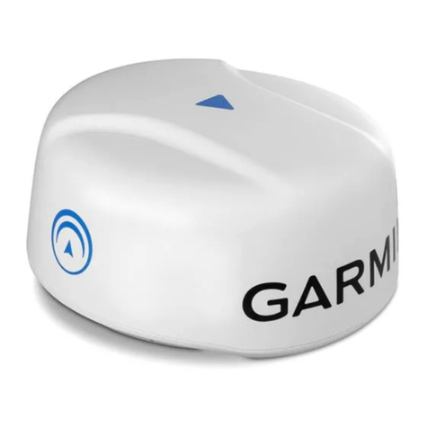
ProNav JMR-5410-4X User manual

JMR-5400 User Manual 20201214 temp 2
JMR-5400 Radar
NB! Some menus depend on the setup during installation and what equipment is connected, so some menus may be missing
from your radar.
Symbols used in the manual
see more info in menu or page
Index
Power unit NQE-3167 for antenna power to JMR-5472 S and JMR-5482 S.....................................................................................5
1. Introduction.................................................................................................................................................................................6
1.1 Radar types ...........................................................................................................................................................................6
Radar Equipment ........................................................................................................................................................................6
Pulse Radar .................................................................................................................................................................................6
Solid state radar/ Chirp S-band Radar ........................................................................................................................................6
1.2 Limitations in radar resolution..............................................................................................................................................7
Separation in distance ................................................................................................................................................................7
Separation in bearing..................................................................................................................................................................8
Minimum detection distance......................................................................................................................................................8
Estimated range on radar ...........................................................................................................................................................9
Deflection of radar signal............................................................................................................................................................9
1.3 Echo treatment / filtration..................................................................................................................................................10
Sea noise suppression (STC) and Gain amplification. ...............................................................................................................10
Rain and snow noise suppression.............................................................................................................................................10
Target Tracking (TT) function....................................................................................................................................................10
1.4 Fast moving targets and SART ............................................................................................................................................12
1.5 Optimization for SART display ............................................................................................................................................12
2. Radar settings, enhancement and data processing of the radar image ....................................................................................13
2.1 Gain/Sea/Rain.....................................................................................................................................................................13
2.2 VIDEO LATITUDE .................................................................................................................................................................15
2.3 Video Noise Reduction........................................................................................................................................................16
2.4 AUTO Dynamic Range Control ............................................................................................................................................17
2.5 Prosess switch.....................................................................................................................................................................18
2.6 Interference remover and PRF (Pulse Repetition Frequency) ............................................................................................18
2.7 Enhance, amplification of small echo .................................................................................................................................19
2.8 Echo processing ..................................................................................................................................................................20
2.9 Preset values in function setup:..........................................................................................................................................21
3 Turn on the radar .......................................................................................................................................................................23
3.1 Operation panel ..................................................................................................................................................................23
3.2 PI lines.................................................................................................................................................................................26

JMR-5400 User Manual 20201214 temp 3
3.3 VRM / EBL fixed and floating T / R and unit........................................................................................................................26
3.4 Own track ...........................................................................................................................................................................26
3.5 Pulse length. .......................................................................................................................................................................27
Radar Range..............................................................................................................................................................................28
Silence Alarm Sound .................................................................................................................................................................28
Acknowledge Alarm..................................................................................................................................................................28
Display resolution..........................................................................................................................................................................29
1280*1024................................................................................................................................................................................29
1920*1200 or 1920*1080.........................................................................................................................................................29
MENUES................................................................................................................................................................................30
Right Toolbar .................................................................................................................................30
Adjust Color and brightness ..............................................................................................................................................30
Adjust screen brightness and control panel......................................................................................................................31
Adjust brightness with the MULTI button ................................................................................................................................31
Radar and Chart overlay. ..........................................................................................................................................................31
MAN OVER BORD MOB......................................................................................................................................................32
Messages AIS and NAVTEX..................................................................................................................................................32
Nav data for own ship...............................................................................................................................................................35
Left Toolbox...................................................................................................................................................................................36
Radar setup ...................................................................................................................................................................................37
N UP/ HUP/ CUP .......................................................................................................................................................................37
X2 Zoom knapp .................................................................................................................................................38
Automatic Rain and Sea (STC) Filter) ........................................................................................................................................38
Multi button .............................................................................................................................................................................38
EBL/Reference point .................................................................................................................................................................39
Reading of distance in NM / km or SM .....................................................................................................................................40
Display info ...............................................................................................................................................................................41
Chart......................................................................................................................................................................................43
Chart info ..................................................................................................................................................................................43
Take a picture, Screen dump .................................................................................................................................................44
Copy picture to USB .............................................................................................................................................................44
Automatic image storage..........................................................................................................................................................45
CURSOR ..........................................................................................................................................................................................45
Cursor symbols ..............................................................................................................................................................................46
General menu............................................................................................................................................................................47
MENU Icones .................................................................................................................................................................................48

JMR-5400 User Manual 20201214 temp 4
Anchor watch ................................................................................................................................................................48
Chart ..............................................................................................................................................................................48
User Chart ......................................................................................................................................................................48
TT/AIS ..............................................................................................................................................................................48
Tool box..........................................................................................................................................................................48
Setting...............................................................................................................................................................................49
Tools................................................................................................................................................................................49
Views................................................................................................................................................................................49
Alarm ..............................................................................................................................................................................49
Hjelp.................................................................................................................................................................................50
Code................................................................................................................................................................................50
Service menu ..................................................................................................................................................................50
TT AIS target....................................................................................................................................................................51
Setting..............................................................................................................................................................................56
Menu>Toolbox ..................................................................................................................................................................62
Alert.................................................................................................................................................................................... 63
Menu Maintenance ............................................................................................................................................................64
View ......................................................................................................................................................................................66
•Kontroll.....................................................................................................................................................................70
Inter switch....................................................................................................................................................................................73
Most often incorrect operation, eg Master processor is not turned on and then you try to connect another processor as a
slave and operating voltage to the antenna is set up so that only paired antenna / Display has power supply to the antenna.
..................................................................................................................................................................................................74
Change ISW setup.....................................................................................................................................................................74
Rename ISW units.....................................................................................................................................................................74
List of icons used in the radar........................................................................................................................................................75
AIS and Target symbols .................................................................................................................................................................79
13.2 AIS symbol types and definitions ......................................................................................................................................79
«Normal» alarm messages ............................................................................................................................................................83

JMR-5400 User Manual 20201214 temp 5
Service menu for user....................................................................................................................................................................85
Kode ..................................................................................................................................................................................85
Service meny......................................................................................................................................................................85
Enter license codes........................................................................................................................................................................86
Operate channel selector on JHS-800 ...........................................................................................................................................86
VHF JHS800 Operation menus on radar ........................................................................................................................................87
VHF MENYER.............................................................................................................................................................................87
DSC call with help of AIS ...........................................................................................................................................................88
Power unit NQE-3167 for antenna power to JMR-5472 S and JMR-5482 S
The circuit breaker disables in case of overvoltage or overload. If this happens, communication from the antenna will stop and
various alarms may appear, TXRX data is one of them.
NQE-3167
46*46 cm
internal
Fuse CB801 overvoltage& overload protection.
F1 and F2 to neck heater
1rst English 20200709
Roger Schultz

JMR-5400 User Manual 20201214 temp 6
1. Introduction
1.1 Radar types
Radar Equipment
Use the radar only as a navigation aid. The crucial decisions about navigation must always be made by the operator. Navigating
only by radar can lead to accidents such as collisions or grounding.
There are two technologies that apply to radar, pulse and solid state (Chirp)
Pulse Radar
Pulse radar uses a magnetron to create the transmitter pulse.
It's a cheap and straightforward way to produce a powerful transmitter pulse. The magnetron
must be annealed to work, the filament will weaken after a while and the magnetron must then
be replaced. The service life depends on the method of use and possible vibration.
Solid state radar/ Chirp S-band Radar
The chirp signal is a frequency modulated transmitter pulse. The frequency modulated transmitter pulse goes from 4.6µs, 9.6µs
or 18.1µs depending on the radar range. The frequency of this signal is 3060MHz + 4MHz
The transmitter starts with low frequency then the
frequency increases linearly. In order to utilize the
entire transmitter signal, the receiver has delayed
circuits on the video (radar) signal, mostly on low
frequencies and less on higher frequencies. The result
will be that echoes to one target are detected with
different frequency, but at the same time. When the
signal is summed in the receiver, echoes in the same
phase are summed to one strong echo, while noise is
suppressed. Have tried to illustrate this on the next
page.
The low frequencies are delayed the most and then less delay
at the higher frequency.
The goal of this delay is that reflections from one echo come
out of the receiver at the same time and are combined into
one powerful echo.
Chirp signal
sends pulse
increases in
frequency through
transmitting heart

JMR-5400 User Manual 20201214 temp 7
Have tried to show this graphically in time axis, the lowest frequencies are delayed the most as it is the one that was sent out first
and goes through all the delay circuits. Higher frequencies are delayed less so that the echoes with different frequency come
through the receiver at the same time and at the end of the receiver are summed and mixed into one strong echo.
The signals is delayed each
time it goes through the
delay circuit
The signals arrive
at the same time
Signals
Filtered,
Summed and
amplified
End pulse
sum of all
pulses
Time axis
Low frequency
Medium
frequency
High frequency
The problem with such a long transmitter pulse is that it is not possible to receive an echo if the pulse is transmitted. Transmitting
the pulse in the longest range will shade out to 1.5Nm. To solve this problem, a short signal is transmitted on one at a different
frequency than the long transmitter pulse. This signal is used to create the radar image close to the boat.
The pulse length of this is 0.07µs - 1.14µs depending on the area of the radar, which is like the transmitter pulse of a magnetron
radar, the frequency of this radar is 3035MHz.
The pulse that changes in frequency 3060 or 3065 and changes ± 4MHz and is 4.6µS to 18.3µS depending on the distance setting
on Radar, Both signals are then used to create a radar image that goes from the center and all the way to the maximum range
1.2 Limitations in radar resolution.
Separation in distance
The radar pulse moves out of the radar at 300m / µS (microsecond).
overall speed is then 150m / µS
If the transmitter pulse is 1µS, two targets must be at distance more
than 150m, then echo number 2 will come as a separate echo and
not as an extension of echo 1. To separate echo, select shorter
transmitter pus.
The differentiating capability of a CHIRP radar depends more on the
narrow bandwidth of the filters in the receiver

JMR-5400 User Manual 20201214 temp 8
Separation in bearing
If there are two echoes next to each other, the radar «beam» must leave the first echo before it hits target no. 2 to be able to
separate the echoes from each other.
Minimum detection distance
If the antenna is placed high, the echo approaching the boat will come under
the radar beam and thus not appear in the radar image. Here comes and goes
the problem of shadow from the hull. IMO is ready in requirements for radar
installation
The antenna must not be mounted so that there is something that shades it at a
longer distance from the boat than:
For boats under 250 m, two boat lengths
For boats over 250m, maximum shade is 500m

JMR-5400 User Manual 20201214 temp 9
Estimated range on radar
Since the radar beam is not normally deflected much, it can be said that the height of the antenna and the height of the target
determine the range (+ that the target gives a usable stable echo)
= 2.23 (√ℎ1 + √ℎ2) Height in meter and distance D will be in Nm
Simple memory rule 10m ant height and 10 m height on the target, then it should be displayed at 15NM.
If the antenna height is 10m and you see a target of 64NM, you can assume that the target has a height above 660m.
Deflection of radar signal
Temperature layers can cause deflections that affect range
Even temperature gives the right beam
Cold air over warm seas can bend the radar beam
Warm air over the cold sea will be able to bend the beam down and you can see echoes "below" the horizon.

JMR-5400 User Manual 20201214 temp 10
1.3 Echo treatment / filtration
NB! In order for the filter to work optimally, the gyro signal should reach 50 times / sec as well as the correct speed indication
from Log and GPS.
Sea noise suppression (STC) and Gain amplification.
These two functions are related to the fact that Gain indicates the maximum gain used and STC reduces this at short range.
Short-range gain then varies depending on how much Sea (STC) is set and up to the maximum gain specified by the Gain button.
Amplification
Diistance
Adjust Gain at long range and use STC / Sea noise to adjust the gain at short range.
When the Sea function is in use, never set the suppression level too high. This may mean that echoes near the vessel are not
displayed. Then it is not only echo from waves that are attenuated, but also echoes from ships and other objects are removed
from the screen. Be sure to use as little Sea as possible.
If this is set to Auto, the radar will adjust the Sea Noise function in 15 ° sectors around the boat, but you have the option to
manually adjust the starting point of sea noise with the SEA button. If you walk in narrow waters and use the Sea damper
function, be aware that the damping can change with the conditions, it is especially important to follow where the landscape
changes sharply.
Rain and snow noise suppression.
When using this function, never set the suppression level too high. This will mean that all echoes, even those that are not due to
rain or snow, can be attenuated so much that they do not appear on the screen.
When using this function, be sure to use the most appropriate noise suppression function
Target Tracking (TT) function
Use target tracking only as a navigation aid. The crucial decisions about navigation must always be made by the operator.
Navigating only by radar can lead to accidents.
Information about tracked targets, such as vector, target numeric data, and alarms may contain errors. Targets not detected on
the radar cannot be displayed or tracked. Navigating only by radar can lead to accidents such as collisions or grounding.

JMR-5400 User Manual 20201214 temp 11
Echo magnification
Echo magnification
Enhance echo is selected level from Off to level3. this makes the echoes a little bigger.
This happens both in distance detection and bearing [azimuth].
For distance, each measuring point is checked and compared with the nearest ones, in the drawing below the measuring point
with echo is shown as X, echo that is magnified is shown with o. If there is no filtering, each measuring point that has data will be
displayed on the screen, this will small noise pulses will be shown in the picture, see line 1/1. By checking several measuring
points against each other, and only showing the result when, for example, 3 of 5 points has an echo signals, a small echo
consisting of three echo points of 5 will be shown as one echo with a size of 5 points, see line 3/5 . Goals with 3 contiguous echo
points will be magnified both ways.
This means that small echoes will increase in percentage much more than large echoes.
For bearing (azimuth), each transmission is checked against the previous one to check if there is a real echo or just a noise pulse.
Echo presentation
When the echo is filtered and is to be displayed on the screen, the presentation depends on how it is to be
displayed on the selected Process function.
Radar echoes are stored in a geographical memory, which is updated using position, course, and speed. With
the help of this memory, depending on which processing is selected, you can filter out unwanted noise such as
sea echoes, echoes that are not repeated at the same geographical position, as well as amplify real echoes that
are repeated at the same position.
. . . . . . . . . . . .
Echoes that are drawn on the same geographical position can, depending on the selected process, see below, be drawn so that
the echo is displayed stronger for each swipe, 3,4, and 5 scan processing. In this way, sporadic echoes will only be displayed with
minimum brightness.

JMR-5400 User Manual 20201214 temp 12
1.4 Fast moving targets and SART
Procedure for detecting moving echoes
The radar has a feature for improving the detection of fast-moving radar echoes.
Fast Target Detection See menu under
MENY + Setting
Setting meny
Undermeny
Oppsett
Echo
Signal process
Video Latitude
Normal
Receiver Band Width
Video Noise Rejection
Level1(low)
Noise control / processing
Auto Dynamic Rng Kontroll
Auto Dyn. control, for
automatic distance, but
you can select different
processing types at short
and long distances as well
as the distance where the
shift is
Process Switch
Process Switch
Off
2nd Proc mode
Remain
Process Switch Range
3.0 NM
Fast Target Detection
If there are fast targets that are not
displayed well enough, you can select
Fast target and the targets will then be
displayed at full strength at the first
swipe.
SART
SART is used if SART signals are weak and
occasionally filtered out as noise..
1.5 Optimization for SART display
To optimize the echo display from the SART transponder, the SART mode must be turned on.
Select scale to 6 or 12 miles, then select Delicate See menu above
If the function is not used, SART echoes will be displayed but they will be weaker in strength.
Indication that the SART function is active can be
found in the lower left corner where the tune info is
Select both Fast Target Detection and SART on.

JMR-5400 User Manual 20201214 temp 13
2. Radar settings, enhancement and data processing of the radar image
2.1 Gain/Sea/Rain
Adjust Rain, Sea and Gain with the buttons.
Normally adjust Gain at long range and remove sea at short distance with sea, then you should normally be able to change the
scale without having to readjust on these.
[SEA], Manual: Mutes sea echo with selected STC level
[SEA], Auto: Automatically mutes sea echo and tries and keeps level around the entire boat. In bearings where there is no
sea echo, the sensitivity is not reduced compared to manual STC, so that echoes and land are displayed with
normal strength. You can also use manual adjustment of extra damping by turning the STC knob.
[RAIN] Manual: Suppresses echo from rain and snow effect is determined by setting the rain button.
[RAIN] Auto: Automatically suppresses echoes from rain and snow in the direction of rain / snow echoes. This mode only
attenuates rain / snow echoes even with scattered rain showers.
Original radar image without STC or Rain attenuation
Auto SEA Function
Auto RAIN function
Auto SEA + zero Rain
Auto rain
Mute noise with SEA auto + 40% and 0% manual Rain

JMR-5400 User Manual 20201214 temp 14
Auto SEA Function
Auto RAIN function
Rain Auto + 40% with 30% Rain manual
Auto Rain 40% manual Sea
Note that Auto Sea do not reduce land echo as much as manual Sea.

JMR-5400 User Manual 20201214 temp 15
2.2 VIDEO LATITUDE
Setting menu
Sub Menu
Setting
Echo
Signal process
Video Latitude
Normal
Video Noise Rejection
Level1(low)
Auto Dynamic Range Control
Process Switch
Process Switch
Off
2nd Proc mode
Remain
Process Switch Range
3.0 NM
The band width of the receiver has a lot to say for noise reduction. In areas with a lot of heavy rain echo, try Super wide
bandwidth.
Bandwidth Application
Narrow: To achieve better strength / contrast on radar echoes.
Normal: Standard use
Wide: Shows targets and other unnecessary noise differently by increasing echo levels.
Super Wide: Shows targets and other unnecessary noise differently by increasing multiple echo levels
Echo in rain without damping Manual Sea and Rain. Band width narrow
Manual Sea and Rain. Band width Norma Manual Sea and Rain. Band width Wide
Manual Sea and Rain. Band width Super Wide

JMR-5400 User Manual 20201214 temp 16
2.3 Video Noise Reduction
Setting menu
Sub Menu
Setting
Echo
Signal process
Video Latitude
Normal
Video Noise Rejection
Level1(low)
Auto Dynamic Rng Control
Process Switch
Process Switch
Off
2nd Proc mode
Remain
Process Switch Range
3.0 NM
・Eliminates signals that are assumed to be noise and clutter from the radar image
・Select "Off" when viewing the radar video without digital processing.
・Select "Level1 (Low)" or "Level2 (High)" to suppress noise and clutter from the screen.
・The operating characteristics of the video noise removal function are as follows.
Off: Sets noise rejection to Off and displays all signal levels.
Displays echoes floating in the noise.
Level 1 (Low): Eliminates echoes that are assumed to be unwanted clutter and noise.
Displays echo clearly defined as echo and echo that cannot be defined as noise or unwanted clutter.
Level 2 (High): Displays signals that are clearly defined as signals.
Eliminates definable echoes as well as echoes that are assumed to be unwanted clutter and noise.
Video Noise reduction Off Video Noise Reduction Level 2
Displays unwanted noise in low echo level and
radar echo that "floats" on top of the noise
Removes signals that are recognized as noise
and shows only radar echoes.

JMR-5400 User Manual 20201214 temp 17
2.4 AUTO Dynamic Range Control
・Automatically controls video bandwidth (dynamic range).
・This function automatically sets the bandwidth to wide when you are in an area with strong sea or rain noise.
. In other areas, the automatic bandwidth is set to narrow to increase sensitivity
Setting menu
Sub Menu
Setting
Echo
Signal process
Video Latitude
Normal
Video Noise Rejection
Level1(low)
Auto Dynamic Rng Control
Process Switch
Process Switch
Off
2nd Proc mode
Remain
Process Switch Range
3.0 NM
Automatic dynamic control is used when you are in an area with varying heavy rainfall

JMR-5400 User Manual 20201214 temp 18
2.5 Prosess switch
Setting menu
Sub Menu
Setting
Echo
Signal process
Video Latitude
Normal
Video Noise Rejection
Level1(low)
Auto Dynamic Rng Control
Process Switch
Process Switch
ON
2nd Proc mode
Remain
Process Switch Range
3.0 NM
Here you can choose whether to have different radar treatment processes in the long and short distance
Do not select process switch range in an area with a lot of sea noise.
2.6 Interference remover and PRF (Pulse Repetition Frequency)
These two are connected, if you get noise from another radar, you can either use interference remover or change how often the
radar transmits. If you have mounted two radars in the same band, you may want to change the PRF on one of them
IR is selected directly from the menu in the lower left corner.
IR Low, IR Medium and
IR High. The IR High setting also affects the sensitivity.
PRF is set in the menu
MENY TXRX
TXRX PRF Fine Tuning
Staggered Trigger
PRF Normal(Juster 1 til 30 Hz)
Ice Class Standby Mode (Antenna
rotates in stby)

JMR-5400 User Manual 20201214 temp 19
2.7 Enhance, amplification of small echo
ENH Off: Sets the target enhancement function to OFF. Set this function to Off when the resolution is especially needed.
ENH Level1: Improves the radar echo by 1 level in the vertical and horizontal directions on the screen. Use for normal navigation
ENH Level2: Improves the radar echo by 2 levels in the vertical and horizontal directions on the screen.
Improve the visibility of the radar image
ENH Level3: Improves the radar echo by 3 levels in vertical and horizontal direction on the screen.
Discover small targets LIKE bouys
Caution
・When [ENH Level3] is selected, sea noise around your own ship may increase. Using [SEA] (Sea noise function) to suppress the
noise reduces the sensitivity at short distances. General use [ENH Level1] or [ENH Level2].

JMR-5400 User Manual 20201214 temp 20
2.8 Echo processing
Process off, echo comes and goes
Proc
Use
Processing
Off
Normal / Fast targets /
SART
No processing
3 Scan
At strong Sea / RAIN
echoes to see clearer
echoes that are hidden
under Sea and Rain
echoes
Here, the intensity of the radar echo is built up
per sweep (antenna rotations) so that sporadic
echoes that are not repeated at the same
geographical position are displayed with low
intensity.
The disadvantage of this filtering is that echoes
from fast boats can be filtered so that they do
not reach full intensity, but they will appear at
low intensity.
Speed direction
This function can be improved for fast echo in process setting by setting detection
to on, see below. If the echoes are small and moving fast, you can also use High
Speed RPM antenna, speedboat radar.
4 Scan
5 Scan
Remain
If the boat gears a lot
The echoes come with full force, and are dimmed on the subsequent sweeps
Peak hold
For detecting small fast
going echoes
The echoes come in with full force and the intensity of the echoes is kept in 4-6
swipes and then dimmed down.
Radar echo is displayed, and noise is muted
This manual suits for next models
9
Table of contents


