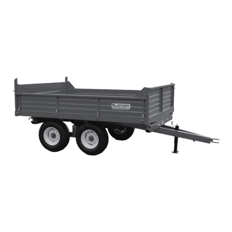
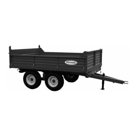
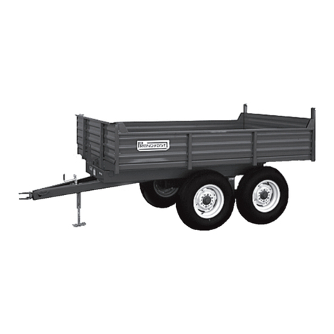
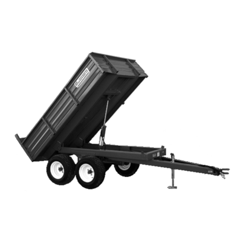
pronovost P-509 User manual

Dump Trailers
Models
No. C1152 06/98
P-509 P-511
OPERATOR'S / PARTS
MANUAL

Copyright © Les Machineries Pronovost Inc., 1999
All rights reserved.
Printed in Canada.

TABLE OF CONTENTS
- 3 -
Section Item Page
1 Introduction .................................................................................................................. 5
2 Safety .......................................................................................................................... 6
GeneralSafety .................................................................................................... 6
SafetyinOperation ............................................................................................. 6
SafetywithMaintenance ..................................................................................... 7
SafetyinTransport ............................................................................................. 7
SafetyinStorage ................................................................................................ 7
3 Decals .......................................................................................................................... 8
SafetyDecals ..................................................................................................... 8
MaintenanceDecals............................................................................................ 8
4 Start-up......................................................................................................................... 9
BasicStart-upProcedures .................................................................................. 9
5 Maintenance .............................................................................................................. 10
6 Storage ....................................................................................................................... 11
7 Specifications ............................................................................................................. 12
8 PartsList.................................................................................................................... 13
DumpTrailersP-509 ........................................................................................ 13
DumpTrailersP-511 ........................................................................................ 15
HubH4000 ...................................................................................................... 17
HubH5000 ...................................................................................................... 18
Cylinder35TR20.............................................................................................. 19
9 TorqueChart.............................................................................................................. 20
10 Warranty .................................................................................................................... 21


Figure1
MODEL:
SERIAL NO:
DATE OF PURCHASE:
INTRODUCTION
- 5 -
NOW take a moment to enter the model, serial number
and the date of purchase of your Trailer in the space
providedbelow.
When ordering parts from your Dealer, please refer to
these numbers for a fast and efficient service. Use
PRONOVOST parts for replacement.
The model and serial numbers are on the name plate
shown on Fig. 1.
Thank you for choosing PRONOVOST. We are
confidentthis equipmentwill meetyour requirements in
termsof quality, performanceand reliability.
This manual was prepared to assist you in the safe
operation of your new Dump Trailer. It contains
importantinformationwhichwillhelpyouachieve
excellent returns with your PRONOVOST Dump
Trailer for years to come.
Please read this manual before operating your Trailer
and keep it for future reference.
Before using this equipment, you or any other person
whowill beusing itmust familiarize yourselfwith the
safety recommendations, the operating and safety
instructions. Please read carefully and be sure to
understand and follow all recommendations and
procedures.
In this manual, the right and left sides are identified
while standing at the rear end of the equipment and
facingit.
Ifyourequire additionalinformation on yourDump
Trailer, please contact your PRONOVOST Dealer.
CONGRATULATIONS! 1

WHEN YOU SEE THIS SYMBOL
SAFETY
- 6 -
ATTENTION!
BE ALERT
YOUR SAFETY IS INVOLVED
This symbol "SAFETY ALERT" is used in this
manual and on the safety decals on the Trailer. It
warns you of the possibility of danger. Carefully read,
understand and follow all safety recommendations
before operating the equipment.
1) Careful operation is the best assurance against
accidents. Carefully read this manual and follow
all recommendations before operating this
equipment. It is the owner’s responsibility to make
sure that anyone who will operate the Trailer will
read this manual before operating the equipment.
2) Do not modify the equipment. Any non authorized
modification may affect the efficiency and/or
safety of the equipment.
3) Never operate the equipment with defective parts
or if damaged in any way. Have it repaired before
usingit.
4) Make sure all fasteners are in place and properly
secured or tightened. Refer to torque chart on
page 20.
5) Hydraulic fluids under pressure can damage your
GENERAL SAFETY
skin. Do not use your hands to locate a leak.
SAFETY IN OPERATION
1) WARNING! Do not overload your trailer, do not
exceed the load capacity indicated in the
specifications on page 12.
2) Be sure there are no obstructions around the
equipment and that no one stands near the
equipment when in use.
3) Do not operate an engine in a confined or non
ventilated area.
4) Do not perform any adjustments, cleaning,
maintenance or repairs with the engine running on
the towing vehicule. Preferably remove the key
fromtheignition.
5) Be careful when backing-up, make sure you have
goodvisibility.
6) Do not forget to unlock the proper panel before
dumping.
7) Always travel at a safe operating speed following
regulations and common sense. In the case of
agricultural service tires, follow the manufacturer's
specified safe speed. The road speed should be
such as to maintain full control over steering and
braking.
2
SAFETY (cont'd)
- 7 -
SAFETY WITH MAINTENANCE
1) Perform maintenance according to
recommendationscontained in thismanual.
2) Before performing any work under the raised
platform, always install the safety support
provided.
3) If the trailer is hooked up to the tractor while
performing maintenance work, make sure the
engine is not running and preferably remove the
ignitionkey.
SAFETY IN TRANSPORT
1) On public roads, use proper safety lights and check
localregulations.
2
2) Be alert while driving on the road. Never carry
passengers.
SAFETY IN STORAGE
1) If the trailer is to be stored for a certain period of
time, install wooden blocks under the axles. THIS
WILL AVOID ANY ACCIDENTAL
CRUSHING OF ANIMALS OR ANYONE
WHO COULD CRAWL UNDER THE
EQUIPMENT.

DECALS
SAFETY DECALS
The safety decals are affixed wherever special safety
precautions are indicated. Locate them on the
equipment and read them carefully. If a decal is
damaged, lost or illegible, install a new one. The
following photos indicate where each one must be
installed.
- 8 -
3
Figure2
Decal A Part no.: A110
Figure3
MAINTENANCE DECALS
The maintenance decals indicate the points requiring
lubrication. Refer to maintenance section for more
details.
Figure5 Part no.: A 106
Figure4 Part no.: A 105

START-UP
- 9 -
7) Verify for adequate tightness of all fastening
devices. Refer to torque chart on page 20.
8) Operate the hydraulic system a few times, raising
and lowering the platform in order to remove any
trapped air in the system. Then check the oil level
in the tractor's hydraulic oil reservoir.
9) Do not forget to unlock the proper panel before
dumping.
BASIC START-UP PROCEDURES
1) Lubricate all grease fittings with a good quality
multiuse grease.
2) Lubricate panel release mechanism, front and rear
withgoodqualityoil.
3) Adjust tire pressure to manufacturer's
specifications.
4) Install wheels on hubs.
5) Installpanels.
6) Installallhydraulichosesandfittingscompatible
withyourequipment.
4

MAINTENANCE
5) Lubricate panel release mechanism, front and rear,
every 20 hours of operation.
6) Check tire pressure every 50 hours of operation,
adjust according to manufacturer's
recommendation indicated on the tires.
7) Open, clean and lubricate wheel bearings once a
year.
8) Check all nuts and bolts once a year. If necessary
use torque chart on page 20.
- 10 -
5
Before performing any work under the raised
platform, always install the safety support
provided.
1) Wipe off all grease fittings with a clean cloth
before adding grease in order to avoid injecting dirt
or sand.
2) Repair or replace damaged grease fittings.
3) Lubricate all grease fittings every 20 hours of
operation.
4) Check all bolts on wheels after first 5 hours of
operation and then every 50 hours of operation.

STORAGE
1) Store in a cool, dry place.
2) Install wooden blocks under the axles to keep the
tires off the ground and cover them if left exposed
to the sun.
3) Keep all piston rods in the retracted position. This
will assure better protection against the elements.
4) Clean your trailer.
5) Thoroughly inspect all parts of the trailer. Replace
or repair worn or defective parts.
6) Touch-up or repaint if necessary.
7) Lubricate all points before storage.
- 11 -
6

SERVICE AGRICULTURAL AGRICULTURAL
MODEL P-509 P-511
Capacity 8000 lbs / 3632 kg 10000 lbs / 4540 kg
Interior dimensions of box 65" x 106" / 1651 mm x 2692 m 65" x 106" / 1651 mm x 2692 mm
Thickness (bottom of the box) 3/16" / 4.78 mm 3/16" / 4.78 mm
Height: Side panel 12G * 14" / 356 mm 14" / 356 mm
Height: Front/back panel 12G * 19" / 483 mm 19" / 483 mm
Platform height 35" / 889 mm 35" / 889 mm
Overall length 147" / 3734 mm 147" / 3734 mm
Overall width 70" / 1778 mm 70" / 1778 mm
Overall height 50" / 1270 mm 50" / 1270 mm
Free height / maximum lift 14" / 356 mm 14" / 356 mm
Thread width 51" / 1295 mm 51" / 1295 mm
Dumping angle (back) 47° 47°
Dumping angle (2 sides) -- --
Axle Simple Tandem
Suspension -- --
Grain door Option Option
Hubs 6 bolts 6 bolts
Hub capacity 5000 lbs / 2270 kg 5000 lbs / 2270 kg
Spindles 2" / 51 mm 1 3/4" / 44 mm
Wheels 2 4
Wheel dimensions 15 x 8 x 6 15 x 6 x 6
Tires (standard) 11L15 (8 ply) 9,5L15 (8 ply)
Hitch: clevis/swivel standard standard
Hitch: ball coupler opt. 2 5/16" / 59 mm opt. 2 5/16" / 59 mm
Electric brakes -- --
Light system (12 V) -- --
Oil / volume required -- --
Cylinder 2 double acting 2 double acting
Hitch weight (empty) 135 lbs / 61 kg 135 lbs / 61 kg
Total weight 1815 lbs / 824 kg 1890 lbs / 858 kg
* Removable panels.
Design and specifications subject to change without notice.
SPECIFICATIONS
- 12 -
7

DUMP TRAILER P-509
- 13 -
8

REF. PART # DESCRIPTION QTY
1 120-01141 Main frame ............................................................................................................. 1
2 110-08961 Cross-beam (from serial number 5541 and up) ............................................................ 1
3 150-00311 Axle 2" ø (welded) .................................................................................................. 2
4 51441 Complete hub assembly H-5000 .............................................................................. 2
5 PN11L15 Tire 11L15 8-ply with tube ...................................................................................... 2
6 R1586 Rim 15" x 8" - 6 holes ............................................................................................ 2
7 Std. Bolt 1/2" NC x 1 1/2" lg + nylon locknut ................................................................. 8
8 Std. Bolt 5/8" x 2 1/2" lg + nylon locknut ....................................................................... 1
9 160-04721 Safety support ........................................................................................................ 1
10 110-08971 Clevis 1" ø x 5 1/4" lg ............................................................................................ 2
11 Std. Cotter pin 3/16" x 2" lg .......................................................................................... 2
12 Std. Grease fitting 1/4" - 28 straight ................................................................................ 3
13 110-03741 Right side panel ...................................................................................................... 1
14 120-01151 Platform ................................................................................................................. 1
15 Std. Bolt 1/2" NC x 2" lg + nylon locknut ....................................................................... 1
16 130-09991 Rear panel lock ....................................................................................................... 1
17 51435 Yoke 1/2" NF + nut 1/2" NF + clevis 1/2" ø x 1 3/4" lg & cotter pin 1/8" x 3/4" lg ..... 1
18 110-03711 Rod 1/2" for rear panel lock ...................................................................................... 1
19 Std. Bolt 1/2" NC x 3 1/2" lg + nylon locknut ................................................................. 2
20 120-01111 Rear panel with grain door ........................................................................................ 1
21 110-03731 Standard rear panel .................................................................................................. 1
22 110-03742 Left side panel ........................................................................................................ 1
23 Std. Bolt 3/8" NC x 2 1/2" lg + nylon locknut & flat washer .............................................. 4
24 110-03751 Front panel ............................................................................................................. 1
25 Std. Bolt 1/2" NC x 1" lg + lock washer .......................................................................... 2
26 160-04731 Spacer 33/64" i.d. x 27/32" o.d. x 1/2" lg ............................................................... 2
27 150-01831 Pin 1/2" ø x 1 1/4" lg ............................................................................................. 1
28 110-08981 Lever for rear panel locking mechanism ....................................................................... 1
29 150-01841 Clevis pin 1" ø x 3 1/8" lg ....................................................................................... 2
30 Std. Hitch pin clip 3/16" ................................................................................................ 4
31 35TR20 Cylinder 35TR20 .................................................................................................... 1
32 Std. Elbow 90° x 1/2" NPT - MF .................................................................................... 1
33 190-00661 Hose 3/8" x 158" lg + 2 fittings 6U-108 ................................................................. 1
34 190-00651 Hose 3/8" x 170" lg + 2 fittings 6U-108 ................................................................. 1
35 110-08991 Swivel hitch ........................................................................................................... 1
36 160-04741 Ring ...................................................................................................................... 1
37 Std. Bolt 1/2" NC x 3"lg + nylon locknut ........................................................................ 1
38 51407 Jack ...................................................................................................................... 1
39 51408 Pin for jack ............................................................................................................. 1
- 14 -
DUMP TRAILER P-509
8

DUMP TRAILER P-511
- 15 -
8

DUMP TRAILER P-511
- 16 -
REF. PART # DESCRIPTION QTY
1 120-01141 Main frame ............................................................................................................. 1
2 110-09001 Left tandem frame .................................................................................................... 1
3 160-01091 Brass bushing 1 3/4" d.i. x 2" d.e. x 2" lg ................................................................ 4
4 Std. Grease fitting 1/4" - 28 straight ................................................................................ 5
5 110-09002 Right tandem frame ................................................................................................. 1
6 150-01851 Axle 1 3/4" ø x 11 9/16" lg (welded) ....................................................................... 4
7 Std. Bolt 1/2" NC x 3" lg + nylon locknut ....................................................................... 3
8 110-00011 Pin for tandem 1 3/4" ø x 15 1/4" lg ........................................................................ 2
9 51503 Complete hub assembly H-4000 ............................................................................... 4
10 110-09011 Right tandem assembly ............................................................................................ 1
NI* 110-09012 Left tandem assembly .............................................................................................. 1
11 PN-9.5L15 Tire 9.5L15 - 8 ply with tube ................................................................................... 4
12 R-1566 Rim 15' a 6" - 6 holes ............................................................................................. 4
13 Std. Bolt 1/2" NC x 1 1/2" lg + nylon locknut ................................................................. 8
14 110-09021 Cross-beam (from serial number 5541 and up) ............................................................ 1
15 Std. Bolt 5/8" NC x 2 1/2" lg + nylon locknut ................................................................. 1
16 160-04721 Safety support ........................................................................................................ 1
17 110-08971 Clevis pin 1" ø x 5 1/4" lg ....................................................................................... 2
18 Std. Cotter pin 3/16" x 2" lg .......................................................................................... 2
19 110-03741 Right side panel ...................................................................................................... 1
20 120-01151 Platform ................................................................................................................. 1
21 Std. Bolt 1/2" NC x 2"lg + nylon locknut ........................................................................ 1
22 130-09991 Rear panel lock ....................................................................................................... 1
23 51435 Yoke 1/2" NF + écrou 1/2" NF + clevis pin 1/2" ø x 1 3/4" lg & cotter
pin 1/8" x 3/4" lg ................................................................................................... 1
24 110-03711 Rod 1/2" for rear panel lock ...................................................................................... 1
25 Std. Bolt 1/2" NC x 3 1/2" lg + nylon locknut ................................................................. 2
26 120-01111 Rear panel with grain door ........................................................................................ 1
27 110-03731 Standard rear panel .................................................................................................. 1
28 110-03742 Left side panel ........................................................................................................ 1
29 Std. Bolt 3/8" NC x 2 1/2" lg + nylon locknut & flat washer .............................................. 4
30 110-03751 Front panel ............................................................................................................. 1
31 Std. Bolt 1/2" NC x 1 " lg + lock washer ......................................................................... 2
32 160-04731 Spacer 33/64" i.d. x 27/32" o.d. x 1/2" lg ............................................................... 2
33 150-01841 Clevis pin 1" ø x 3 1/8" lg ....................................................................................... 2
34 Std. Hitch pin clip 3/16" ................................................................................................ 4
35 35TR20 Cylinder 35TR20 .................................................................................................... 1
36 150-01831 Pin 1/2" x 1 1/4" lg ................................................................................................ 1
37 110-08981 Lever for rear panel locking mechanism ....................................................................... 1
38 Std. Elbow 90° x 1/2" NPT - MF .................................................................................... 1
39 190-00661 Hose 3/8" x 158" lg + 2 fittings 6U-108 ................................................................. 1
40 190-00651 Hose 3/8" x 170" lg + 2 fittings 6U-108 ................................................................. 1
41 110-08991 Swivel hitch ........................................................................................................... 1
42 160-04741 Ring ...................................................................................................................... 1
43 51407 Jack ...................................................................................................................... 1
44 51408 Pin for jack ............................................................................................................. 1
NI*= Not illustrated
8

HUB H4000 #51503
- 17 -
8
REF. PART # DESCRIPTION QTY
1 Std. Cotter pin 5/32" x 1 1/2" ............................................................................ 1
2 51528 Dust cap D-4000 2 5/16" ø .......................................................................... 1
3 51529 Castle nut 1" NF x 9/16" thick ...................................................................... 1
4 Std. Flat washer 1" ........................................................................................... 1
5 51530 Roller bearing: cone no. LM67048 .................................................................. 1
6 51531 Roller bearing: cup no. LM67010 .................................................................... 1
7 51418 Rim screw 9/16" ........................................................................................ 5
8 51532 Hub only H4000 ......................................................................................... 1
9 51533 Roller bearing: cup no. LM29710 .................................................................... 1
10 51534 Roller bearing: cone no. LM67048 .................................................................. 1
11 51535 Oil seal no. CR17415 ................................................................................... 1

HUB H5000 #51441
- 18 -
REF. PART # DESCRIPTION QTY
1 Std. Cotter pin 5/32" x 1 1/2" ............................................................................ 1
2 51417 Dust cap 2.570" ø ...................................................................................... 1
3 51442 Castle nut 7/8" NF ...................................................................................... 1
4 Std. Flat washer 7/8" ........................................................................................ 1
5 51416 Roller bearing: cone no. 4T-LM48548 ............................................................. 1
6 51415 Roller bearing: cup no. 4T-LM48510 ............................................................... 1
7 51418 Rim screw 9/16" ........................................................................................ 6
8 51414 Hub only H5000 ......................................................................................... 1
9 51413 Roller bearing: cup no. 4T-LM603011 ............................................................. 1
10 51412 Roller bearing: cone no. 4T-LM603049 ............................................................ 1
11 51443 Oil seal no. CR20044 ................................................................................... 1
8

CYLINDER 35TR20
- 19 -
REF. PART # DESCRIPTION QTY
1 Voir RK35TR125 O-ring .................................................................................................. 2
2 Voir RK35TR125 Back-up ring ......................................................................................... 2
3 Voir RK35TR125 O-ring .................................................................................................. 1
4 Voir RK35TR125 O-ring .................................................................................................. 1
5 Voir RK35TR125 O-ring .................................................................................................. 1
6 Voir RK35TR125 Back-up ring ......................................................................................... 1
7 Voir RK35TR125 Wiper .................................................................................................. 1
8 492403 Yoke (for 3 1/2" tube) ............................................................................ 1
9 Std. Nut 1 1/4" NF ....................................................................................... 1
10 492433 Piston 3 1/2" ø ..................................................................................... 1
11 458600 Piston rod 1 1/4" ................................................................................... 1
12 491810 Cylinder body 3 1/2" ø ............................................................................ 1
13 492423 Cylinder head 3 1/2" .............................................................................. 1
14 Std. Bolt 3/8" NC x 2¼" + nut ...................................................................... 1
15 Std. Nut 3/8" NC ......................................................................................... 8
16 492350 Threaded rod 3/8" NC ............................................................................ 4
17 458600 Yoke (for 1 1/4" rod) .............................................................................. 1
NI* 8183 Pin 1" ø + cotter pin ............................................................................. 2
NI* RK35TR125 Repair kit for cylinder 3" (includes # 1, 2, 3, 4, 5, 6, & 7) ............................. 1
*NI = NOT ILLUSTRATED
8

- 20 -
min. max. min. max. min. max. min. max. min. max. min. max.
M6 UNC 1.00 3.6 5.8 4.9 7.9 5.8 9.4 7.9 12.7 7.2 10 9.8 13.6
M8 UNC 1.25 7.2 14 9.8 19 17 22 23 29.8 20 26 27.1 35.2
M10 UNC 1.5 20 25 27.1 33.9 34 40 46.1 54.2 38 46 51.5 62.3
M12 UNC 1.75 28 34 37.9 46.1 51 59 69.1 79.9 57 66 77.2 89.4
M14 UNC 2.0 49 56 66.4 75.9 81 93 109.8 126 96 109 130.1 147.7
M16 UNC 2.0 67 77 90.8 104.3 116 130 157.2 176.2 129 145 174.8 196.5
M18 UNC 2.0 88 100 119.2 136 150 168 203.3 227.6 175 194 237.1 262.9
M20 UNC 2.5 108 130 146.3 176.2 186 205 252 277.8 213 249 288.6 337.4
M8 UNF 1.0 12 17 16.3 23 19 27 25.7 36.6 22 31 29.8 42
M10 UNF 1.25 20 29 27.1 39.3 35 47 47.4 63.7 40 52 54.2 70.5
M12 UNF 1.25 31 41 42 55.6 56 68 75.9 92.1 62 75 84 101.6
M14 UNF 1.5 52 64 70.5 86.7 90 106 122 143.6 107 124 145 168
M16 UNF 1.5 69 83 93.5 112.5 120 138 162.6 187 140 158 189.7 214.1
M18 UNF 1.5 100 117 136 158.5 177 199 239.8 269.6 202 231 273.7 313
M20 UNF 1.5 132 150 178.9 203.3 206 242 279.1 327.9 246 289 333.3 391.6
Inches mm min. max. min. max. min. max. min. max. min. max. min. max.
1/4 6.35 5 6 6.8 8.13 9 11 12.2 14.9 12 15 16.3 30.3
5/16 7.94 10 12 13.6 16.3 17 20.5 23.1 27.8 24 29 32.5 39.3
3/8 9.53 20 23 27.1 31.2 35 42 47.5 57.0 45 54 61.0 73.2
7/16 11.11 30 35 40.7 47.4 54 64 73.2 86.8 70 84 94.9 113.9
1/2 12.70 45 52 61.0 70.5 80 96 108.5 130.2 110 132 149.2 179.0
9/16 14.29 65 75 88.1 101.6 110 132 149.2 179.0 160 192 217.0 260.4
5/8 15.88 95 105 128.7 142.3 150 180 203.4 244.1 220 264 298.3 358.0
3/4 19.05 150 185 203.3 250.7 270 324 366.1 439.3 380 456 515.3 618.3
7/8 22.23 160 200 216.8 271.0 400 480 542.4 650.9 600 720 813.6 976.3
1 25.40 250 300 338.8 406.5 580 696 786.5 943.8 900 1080 1220.4 1464.5
1 1/8 25.58 - - - - 800 880 1084.8 1193.3 1280 1440 1735.7 1952.6
1 1/4 31.75 - - - - 1120 1240 1518.7 1681.4 1820 2000 2467.9 2712.0
1 3/8 34.93 - - - - 1460 1680 1979.8 2278.1 2380 2720 3227.3 3688.3
1 1/2 38.10 - - - - 1940 2200 2630.6 2983.2 3160 3560 4285.0 4827.4
TORQUE CHART
TORQUE SPECIFICATION TABLE
ThreadUNCandUNF
Use the above torques when special torque is not given.
NOTE: These values apply to fasteners as received from supplier, dry, or when lubricated with normal engine oil. They do
not apply if extreme pressure lubricants are used.
Pound feet Newton meters Pound feet Newton meters Pound feet Newton meters
* Thick nuts must be used with grade 8 bolts.
Boltsize Torque Torque Torque
Torque Torque
Pound feet Newton meters Pound feet Newton meters Pound feet Newton meters
Sizeof
screw
Pitch(mm)
Torque
Grade7T Grade8T
Grade4T
Grade2 Grade5 Grade8*
Thread
9
This manual suits for next models
1
Table of contents
Other pronovost Utility Vehicle manuals

pronovost
pronovost P-511-60 User manual

pronovost
pronovost P-516/3S Programming manual

pronovost
pronovost PUMA-347AG Programming manual

pronovost
pronovost P-509-60 User manual

pronovost
pronovost P-5103S/4E Programming manual

pronovost
pronovost PUMA-LP12 Product manual

pronovost
pronovost P-508/3S Product manual

pronovost
pronovost P-505 Product manual

pronovost
pronovost PUMA-10000 User manual

pronovost
pronovost PUMA-347M Product manual