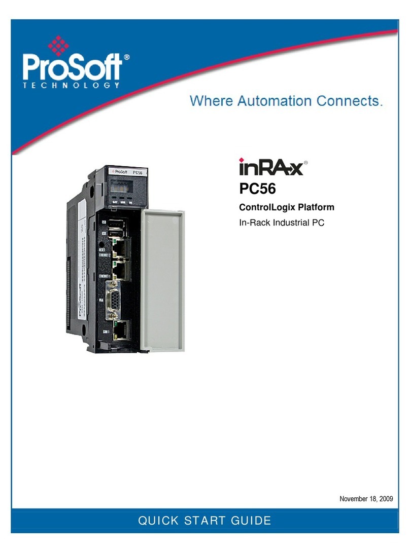
ProSoft Technology InRax PC56 User manual

PC56
ControlLogix Platform
In-Rack Industrial PC
User Manual
January 28, 2008

Please Read This Notice
Successful application of this module requires a reasonable working knowledge of the Allen-
Bradley hardware, the PC56 Module and the application in which the combination is to be used.
For this reason, it is important that those responsible for implementation satisfy themselves that the
combination will meet the needs of the application without exposing personnel or equipment to
unsafe or inappropriate working conditions.
This manual is provided to assist the user. Every attempt has been made to ensure that the
information provided is accurate and a true reflection of the product's installation requirements. In
order to ensure a complete understanding of the operation of the product, the user should read all
applicable Allen-Bradley documentation on the operation of the Allen-Bradley hardware.
Under no conditions will ProSoft Technology be responsible or liable for indirect or consequential
damages resulting from the use or application of the product.
Reproduction of the contents of this manual, in whole or in part, without written permission from
ProSoft Technology is prohibited.
Information in this manual is subject to change without notice and does not represent a
commitment on the part of ProSoft Technology Improvements and/or changes in this manual or the
product may be made at any time. These changes will be made periodically to correct technical
inaccuracies or typographical errors.
Warnings
UL Warnings
A Warning - Explosion Hazard - Substitution of components may impair
suitability for Class I, Division 2.
B Warning - Explosion Hazard - When in Hazardous Locations, turn off power
before replacing or rewiring modules.
Warning - Explosion Hazard - Do not disconnect equipment unless power has
been switched off or the area is known to be nonhazardous.
C Suitable for use in Class I, division 2 Groups A, B, C and D Hazardous
Locations or Non-Hazardous Locations.
ATEX Warnings and Conditions of Safe Usage:
Power, Input, and Output (I/O) wiring must be in accordance with the authority
having jurisdiction
A Warning - Explosion Hazard - When in hazardous locations, turn off power
before replacing or wiring modules.
B Warning - Explosion Hazard - Do not disconnect equipment unless power has
been switched off or the area is known to be non-hazardous.
C These products are intended to be mounted in an IP54 enclosure. The
devices shall provide external means to prevent the rated voltage being
exceeded by transient disturbances of more than 40%. This device must be
used only with ATEX certified backplanes.
D DO NOT OPEN WHEN ENERGIZED.

Electrical Ratings
Backplane Current Load: 800 mA @ 5 V DC; 3mA @ 24V DC
Operating Temperature: 0 to 60°C (32 to 140°F)
Storage Temperature: -40 to 85°C (-40 to 185°F)
Shock: 30g Operational; 50g non-operational; Vibration: 5 g from 10 to 150
Hz
Relative Humidity 5% to 95% (non-condensing)
All phase conductor sizes must be at least 1.3 mm(squared) and all earth
ground conductors must be at least 4mm(squared).
Markings:
II 3 G 0C <=Ta<= 60C EEx nA IIC T4 DEMKO 07ATEX0710717X
Your Feedback Please
We always want you to feel that you made the right decision to use our products. If you have
suggestions, comments, compliments or complaints about the product, documentation or support,
please write or call us.
ProSoft Technology
1675 Chester Avenue, Fourth Floor
Bakersfield, CA 93301
+1 (661) 716-5100
+1 (661) 716-5101 (Fax)
http://www.prosoft-technology.com
Copyright © ProSoft Technology, Inc. 2000 - 2008. All Rights Reserved.
PC56 User Manual
January 28, 2008
PSFT...UM.08.01.28
ProSoft Technology ®, ProLinx ®, inRAx ®, ProTalk® and RadioLinx ® are Registered Trademarks
of ProSoft Technology, Inc.


Contents PC56 ♦ControlLogix Platform
In-Rack Industrial PC
ProSoft Technology, Inc. Page 5 of 33
January 28, 2008
Contents
PLEASE READ THIS NOTICE................................................................................................................2
Warnings............................................................................................................................................2
Your Feedback Please ......................................................................................................................3
1USING THIS MANUAL .....................................................................................................................7
1.1 Who Should Use This Manual ....................................................................................................7
1.1.1 Additional Documentation............................................................................................................ 7
1.2 Reference Material......................................................................................................................8
1.3 Product Specifications.................................................................................................................8
1.3.1 Hardware Specifications.............................................................................................................. 8
1.3.2 Environmental Specifications....................................................................................................... 9
1.3.3 Operating System........................................................................................................................ 9
1.3.4 Engineering Support.................................................................................................................... 9
2INTRODUCING PC56 .....................................................................................................................11
2.1 PC56 Overview .........................................................................................................................11
2.1.1 Features and Benefits ............................................................................................................... 12
2.1.2 Key OEM Features .................................................................................................................... 12
2.1.3 Benefits ..................................................................................................................................... 12
2.1.4 PC56 Architecture ..................................................................................................................... 12
2.1.5 Compatibility Issues................................................................................................................... 13
2.1.6 PC56 Software Tools................................................................................................................. 13
3INSTALLING PC56.........................................................................................................................15
3.1 Setting Jumpers ........................................................................................................................15
3.1.1 Battery Enable/ CMOS Clear..................................................................................................... 15
3.1.2 Battery Enable........................................................................................................................... 16
3.1.3 COM1 Mode Select ................................................................................................................... 16
3.2 Inserting The Module ................................................................................................................16
3.2.1 Turn ON power.......................................................................................................................... 16
4RESET, AUXILIARY TIMERS AND PCI INFORMATION..............................................................17
4.1 Overview ...................................................................................................................................17
4.1.1 Auxiliary Timer (WinCE Only)....................................................................................................17
4.1.2 RESET: Functional Description ................................................................................................. 17
4.1.3 PCI Configuration Base Addresses ........................................................................................... 17
4.1.4 Four Character Alpha-Numeric Display ..................................................................................... 18
4.2 Using the USB Ports .................................................................................................................18
5TROUBLESHOOTING....................................................................................................................19
5.1 FAQ...........................................................................................................................................19
6REFERENCE...................................................................................................................................21
6.1 Memory Map .............................................................................................................................21
7SUPPORT, SERVICE & WARRANTY............................................................................................23
7.1 How to Contact Us: Sales and Support ....................................................................................24
Return Material Authorization (RMA) Policies and Conditions........................................................25
7.1.1 All Product Returns.................................................................................................................... 25
7.2 Procedures for Return of Units Under Warranty.......................................................................25
7.3 Procedures for Return of Units Out of Warranty.......................................................................26
7.3.1 Un-repairable Units.................................................................................................................... 26
7.3.2 Purchasing Warranty Extension ................................................................................................ 27
7.4 LIMITED WARRANTY ..............................................................................................................27
7.4.1 What Is Covered By This Warranty ........................................................................................... 27
7.4.2 What Is Not Covered By This Warranty..................................................................................... 28

PC56 ♦ControlLogix Platform Contents
In-Rack Industrial PC
Page 6 of 33
January 28, 2008
7.4.3 DISCLAIMER REGARDING HIGH RISK ACTIVITIES .............................................................. 29
7.4.4 DISCLAIMER OF ALL OTHER WARRANTIES......................................................................... 29
7.4.5 LIMITATION OF REMEDIES**.................................................................................................. 29
7.4.6 Time Limit for Bringing Suit ....................................................................................................... 29
7.4.7 No Other Warranties ................................................................................................................. 30
7.4.8 Intellectual Property................................................................................................................... 30
7.4.9 Additional Restrictions Relating To Software And Other Intellectual Property........................... 30
7.4.10 Allocation of risks ...................................................................................................................... 30
7.4.11 Controlling Law and Severability ............................................................................................... 31
INDEX.................................................................................................................................................... 33

Using This Manual PC56 ♦ControlLogix Platform
In-Rack Industrial PC
ProSoft Technology, Inc. Page 7 of 33
January 28, 2008
1 Using This Manual
In This Chapter
Who Should Use This Manual .................................................................7
Reference Material ..................................................................................8
Product Specifications.............................................................................8
1.1 Who Should Use This Manual
Use this manual if you are responsible for designing, installing, programming, or
troubleshooting control systems that use the ProSoft Technology PC56 module.
This manual is a guide for using the PC56. How you program PC56 or how your
application functions depends on the software applications you install on PC56.
Because of the variety of uses for the products, those responsible for the
application and use of this control equipment must satisfy themselves that all
necessary steps have been taken to assure that each application and use meets
all performance and safety requirements, including any applicable laws,
regulations, codes and standards.
The illustrations, charts, sample programs and layout examples shown in the
product literature are intended solely for purposes of example. Since there are
many variables and requirements associated with any particular installation,
ProSoft Technology does not assume responsibility or liability (to include
intellectual property liability) for actual use.
1.1.1 Additional Documentation
In addition to this manual there is a PC56 "Getting Started Guide". There are also
API manuals for the various operating systems. The "Windows API Users
Manual" comes on a CD packaged with each PC56.
Each PC56 component ships with installation instructions. The user manuals and
installation instructions are also available from the ProSoft Technology web site
at http://www.prosoft-technology.com.

PC56 ♦ControlLogix Platform Using This Manual
In-Rack Industrial PC
Page 8 of 33 ProSoft Technology, Inc.
January 28, 2008
1.2 Reference Material
This Document By: Has this ISBN #
PC Systems Architecture Series MindShare, Inc. ISBN: 0-201-40993-3
PCI Systems Architecture Addison-Wesley Publishing Co.
PC Systems Architecture Series MindShare, Inc. ISBN: 0-201-40996-8
ISA Systems Architecture Addison-Wesley Publishing Co.
PCI Hardware and Software
Architecture and Design
Edward Solari and George Willse ISBN: 0-929392-28-0
1.3 Product Specifications
1.3.1 Hardware Specifications
Specification Description
CPU Processor Embedded 500 MHz Processor
Memory 512 MB SDRAM System Memory, upgradeable to 1 GB
512 KB SRAM (Battery Backed)
Compact Flash Compact Flash Type I or II socket
Ethernet Port 10/100T IEEE 802.3 Ethernet
1500 V rms at 50 Hz to 60 Hz for 60 s, applied as specified in section
5.3.2 of IEC 60950: 1991
Ethernet Broadcast Storm Resiliency = less than or equal to 5000 [ARP]
frames-per-second and less than or equal to 5 minutes duration
Serial Port Isolated Serial RS-232 / RS-422 / RS-485
USB Port Two USB 2.0 / 1.1 High Speed Host
Connectors VGA, 2 Ethernet, 2 USB
Battery Rechargeable Lithium Vanadium Pentoxide
Jumpers COM 1 Mode Selection
Battery Enable/Clear CMOS
Boot to SAFE STATE (default settings)
Hardware Debugger Support
Switches Recessed Reset Switch
LED/Display 4-digit alphanumeric status display
3 Status LEDs
1 User LED
Red, Green, Off
Real-Time Clock Precision RTC accurate to +/- 4 minutes per year
Timers 82C54 Timer Clock 14 MHz - Interrupt Interval 1.67619 US
Video VGA
1920 x 1440
1280 x 1024 256
1024 x 768 56K
800 x 600 16 M
43 Hz Interlaced 56 through 85 Hz Refresh Rates

Using This Manual PC56 ♦ControlLogix Platform
In-Rack Industrial PC
ProSoft Technology, Inc. Page 9 of 33
January 28, 2008
1.3.2 Environmental Specifications
Item Specification
Temperature Non-Operating: 0 to 80°C
Operating: 0 to 60°C
Note: Storage media may limit operating
Form Factor Single-slot ControlLogix module
Power Ratings 10 W Max power consumption (Backplane powered)
1.3.3 Operating System
The PC56 modules are ordered and shipped with the selected operating system
pre-installed on the module. Operating system versions are as follows:
Windows XP
Windows CE 5.0
1.3.4 Engineering Support
Prosoft Technology. can provide additional technical support to ease and
expedite the development and implementation of applications on the PC56. This
support is available by ordering the PC56 Developer's Support Kit. Contact
ProSoft Technology for additional information.

PC56 ♦ControlLogix Platform Using This Manual
In-Rack Industrial PC
Page 10 of 33 ProSoft Technology, Inc.
January 28, 2008

Introducing PC56 PC56 ♦ControlLogix Platform
In-Rack Industrial PC
ProSoft Technology, Inc. Page 11 of 33
January 28, 2008
2 Introducing PC56
In This Chapter
PC56 Overview .....................................................................................11
2.1 PC56 Overview
The PC56 enables you to easily integrate PLC (Programmable Logic Controller)
and PC (Personal Computer) programs in a single platform. Think of PC56 as a
PC or industrial computer that fits into the Allen-Bradley@1756 ControlLogixTM
chassis.
The differences between PC56 and a normal PC are the added functions to
better address the needs of the industrial controls user. One of these is the
PC56's ability to directly communicate with the Allen-Bradley@1756
ControlLogixTM back plane.
Included with each PC56 are the APIs necessary to develop application code for
a variety of Operating Systems. Currently supported Operating Systems include
Windows CE and XP.

PC56 ♦ControlLogix Platform Introducing PC56
In-Rack Industrial PC
Page 12 of 33 ProSoft Technology, Inc.
January 28, 2008
2.1.1 Features and Benefits
Supports Windows CE or Windows XP
Embedded 500MHz AMD processor
Solid State, reliable operation
10/100 Base-T Ethernet
Direct CLX processor read/write access
Type II Compact Flash socket
Stacking PCI Expansion Bus for high-speed connection to accessory
modules
Available 40 GB IDE Drive PCI Expansion Module
2.1.2 Key OEM Features
The PC56 has several key features designed specifically to allow OEMs to
develop the high performance applications needed in industrial automation
applications:
High Precision Real Time Clock
Applications can be secured to module type and/or to module serial number
Auxiliary timer (CE only)
PowerFail Monitor (Allows data storage to BBRAM)
2.1.3 Benefits
Provides easy data collection connectivity
Rigidly integrates traditional PLC and PC technology
Integrates multiple vendor programs in a single chassis
Enhances the control functions of the ControlLogix platform by adding the
openness and processing power of the PC
Meets net control and information automation requirements
Perfect for tightly integrated OEM applications
Meets new IT requirements
2.1.4 PC56 Architecture
The continuing advances in processor technology have influenced the PC56
architecture. The speed at which new processors are introduced helped
determine that a sub-module approach be used in the design of the PC56. The
PC56 module consists of a two board stack, the ControlLogixTM board and the
CPU board.
The ControlLogixTM board contains the components necessary to communicate
with the 1756 backplane as well as all the physical interfaces on the front of the
module. The PC56 interfaces with the ControlLogixTM backplane through a
shared memory window and uses a PCI interrupt. The memory window and
interrupt are allocated by the system BIOS during the boot process.
The CPU board houses the processor, the PCI chipset and connector and the
Ethernet chipset. These components are most likely to change with new
advances in component technology.

Introducing PC56 PC56 ♦ControlLogix Platform
In-Rack Industrial PC
ProSoft Technology, Inc. Page 13 of 33
January 28, 2008
2.1.5 Compatibility Issues
PC56 is compatible with the Allen-Bradley 1756 ControlLogix chassis, the
processors, ControlLogix software, power supplies, and all ControlLogixTM I/O
modules.
2.1.6 PC56 Software Tools
In each PC56 package there is a CD with the Windows APIs and its manual.
There is also example code included as well as source code for common tasks.
Refer to the API manual for information.

PC56 ♦ControlLogix Platform Introducing PC56
In-Rack Industrial PC
Page 14 of 33 ProSoft Technology, Inc.
January 28, 2008

Installing PC56 PC56 ♦ControlLogix Platform
In-Rack Industrial PC
ProSoft Technology, Inc. Page 15 of 33
January 28, 2008
3 Installing PC56
In This Chapter
Setting Jumpers ....................................................................................15
Inserting The Module.............................................................................16
Review the locations of the communications ports. Use the illustration on the
front door of the module to locate the communication ports. Review the drawings
included in this chapter to locate the jumpers that must be checked and, or
changed as your application requires.
Important: Before you install PC56:
Turn off power to the chassis
Look at the three jumper settings:
oCOM1 port mode setting
oBattery Enable/CMOS Clear
oControlLogix™ Backplane shared memory allocation
3.1 Setting Jumpers
There are three jumpers to set, as your application requires.
3.1.1 Battery Enable/ CMOS Clear

PC56 ♦ControlLogix Platform Installing PC56
In-Rack Industrial PC
Page 16 of 33 ProSoft Technology, Inc.
January 28, 2008
Clearing CMOS Memory
Insert the jumper in the CMOS Clear position momentarily if you want to clear
CMOS memory and install the factory default BIOS settings.
3.1.2 Battery Enable
Place the jumper in the Battery Enable position to enable battery back-up of the
system Real Time Clock, CMOS Memory, and 512 KByte battery-backed SRAM.
If the PC56 is not going to be powered up for a long period of time, then it is
advisable to remove the Battery Enable jumper to prevent complete discharge of
the rechargeable battery.
3.1.3 COM1 Mode Select
Used to set COM1 serial port to one of the three configurations listed.
3.2 Inserting The Module
After you have checked the placement of the jumpers, insert PC56 into the
ControlLogixTM chassis. Use the same technique recommended by Allen-Bradley
to remove and install ControlLogixTM modules.
Align the module with the top and bottom guides and slide into the rack until the
module is firmly against the back plane connector. With a firm but steady push
snap the module into place. Check that the holding clips on the top and bottom of
the module are securely in the locking holes of the rack.
Note: Improper insertion of the module can cause unpredictable system behavior.
Note: If you are installing PC56 with other modules connected to the PCI bus. The peripheral
modules will not have holding clips. Make sure all of the modules are aligned with their respective
slots before you snap them into place.
3.2.1 Turn ON power
The PC56 will go through a POST routine that will check RAM and when
complete will set the OK LED to GREEN. All other LEDs will be blank or OFF,
unless your application sets them.

Reset, Auxiliary Timers and PCI Information PC56 ♦ControlLogix Platform
In-Rack Industrial PC
ProSoft Technology, Inc. Page 17 of 33
January 28, 2008
4 Reset, Auxiliary Timers and PCI Information
In This Chapter
Overview ...............................................................................................17
Using the USB Ports .............................................................................18
4.1 Overview
In addition to the standard PC system hardware, PC56 contains the ControlLogix
back plane interface circuitry with 512 MB SDRAM (upgradeable to 1 GB), an
82C54 timer, 512KBytes of battery-backed SRAM and a four character alpha-
numeric display.
This chapter describes the functionality of the special hardware contained in the
PC56 system.
4.1.1 Auxiliary Timer (WinCE Only)
The 82C54 timer shares a single PCI interrupt with the backplane support
hardware, therefore your software must support sharing of this interrupt if you are
going to use the timer in an application requiring the timer to initiate an interrupt.
The 82C54 timer can also be configured to use the Non-Maskable Interrupt
instead of a PCI interrupt. When the timer is configured to use NMI, then interrupt
sharing between the timer and back plane hardware is not required..
4.1.2 RESET: Functional Description
A hardware reset occurs when the PC56 is powered up or when the reset switch
is depressed. When a hardware reset occurs, the ControlLogix interface circuitry
is reset, and its interrupt is disabled. The 82C54 timer interrupt is also disabled.
4.1.3 PCI Configuration Base Addresses
The PCI configuration space contains the addresses allocated to the shared
RAM of the ControlLogixTM interface circuitry and the SRAM as well as other PCI
relevant addresses. The Vendor ID = 167Ch and Device ID = 0001h.

PC56 ♦ControlLogix Platform Reset, Auxiliary Timers and PCI Information
In-Rack Industrial PC
Page 18 of 33 ProSoft Technology, Inc.
January 28, 2008
4.1.4 Four Character Alpha-Numeric Display
One of the unique features of PC56 is the front panel four character
alphanumeric display. This display can scroll ASCII messages or display simple
error codes. Refer to the API manual for information on how to write to this
display.
4.2 Using the USB Ports
PC56 has two high speed Universal Serial Bus 2.0 (USB) ports for connection to
a variety of USB devices. USB device drivers are normally provided by the USB
device manufacturer.

Troubleshooting PC56 ♦ControlLogix Platform
In-Rack Industrial PC
ProSoft Technology, Inc. Page 19 of 33
January 28, 2008
5 Troubleshooting
In This Chapter
FAQ.......................................................................................................19
If the system has been working properly, verify that the configuration has not
been modified. This includes peripheral PCI module installation, jumper settings,
BIOS settings, and cable connections. If needed, a module swap will verify a
faulty module. Make sure that the system configuration is correct, and that the
module you are replacing the suspect one with is a proven good one.
If the system has not been working properly, or you are installing the module for
the first time, then review the jumper and BIOS settings.
5.1 FAQ
Question:
What do the LEDs mean?
Answer:
BAT - If this LED is ON if the battery is low, or if the Battery Enable jumper is not
installed. As soon as power is applied to PC56, a low battery will begin to charge
and the BAT LED will return to the OFF state within minutes. Twenty hours of
continuous, powered-up operation will fully charge the battery.
USR - This LED is under program control and can be set to RED, GREEN, or
OFF. Review the installed software program guide for information and state
definitions.
OK - On power up, this LED is set to GREEN. During normal operation, if there is
a problem communicating with the ControlLogix backplane it will be set to RED.
This LED is under program and API control. It is sometimes referred to as the
status LED. Refer to your application and the API manual for information.

PC56 ♦ControlLogix Platform Troubleshooting
In-Rack Industrial PC
Page 20 of 33 ProSoft Technology, Inc.
January 28, 2008
Question:
How can I tell if a communications port is working properly?
Answer:
There are two LEDs associated with each communications port: the top one is
green and the bottom one is yellow:
GREEN: Receive LED. This LED will momentarily turn ON when the serial port is
receiving data from another device.
YELLOW: Transmit LED. This LED will momentarily turn ON when the serial port
is transmitting data to another device.
Question:
Is PC56 slot dependent?
Answer:
No, but some consideration should be given to making room for any peripheral
modules you are plugging onto the PCI bus.
Question:
Does the order I plug the PC56 peripherals on to the PCI bus matter?
Answer:
The PC56-IDE module, if used, should always be installed in the first slot to the
left of the PC56 (Slot 0). Slot locations are numbered 0 through 2 starting at the
first slot location to the left of the PC56. The PCI slot assignment jumper for each
PCI peripheral module should be installed to match its corresponding physical
slot location.
Question:
What is the maximum number of peripheral PCI modules I can plug onto PC56?
Answer:
Three unless otherwise specified.
Other manuals for InRax PC56
1
Table of contents
Other ProSoft Technology Industrial PC manuals
Popular Industrial PC manuals by other brands

DMP Electronics
DMP Electronics DIN PC-336 Series user guide

Touch Dynamic
Touch Dynamic Orion user manual

ABB
ABB IndustrialIT Compact HMI 800 Getting started

Moxa Technologies
Moxa Technologies DA-681-I-SP-CE Quick installation guide

GIGAIPC
GIGAIPC QBiX-Plus-KBLA7100-A1 quick start guide

Siemens
Siemens SIMATIC IPC477E operating instructions