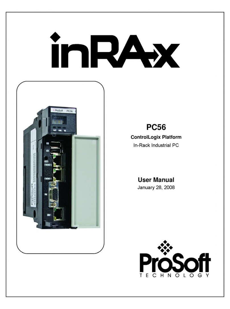
ProSoft Technology InRax PC56 User manual

PC56
ControlLogix Platform
In-Rack Industrial PC
November 18, 2009
QUICK START GUIDE

PC56 Modules
WARNING - EXPLOSION HAZARD - DO NOT DISCONNECT EQUIPMENT UNLESS POWER HAS BEEN
SWITCHED OFF OR THE AREA IS KNOWN TO BE NON-HAZARDOUS.
AVERTISSEMENT - RISQUE D'EXPLOSION - AVANT DE DÉCONNECTER L'EQUIPMENT, COUPER LE
COURANT OU S'ASSURER QUE L'EMPLACEMENT EST DÉSIGNÉ NON DANGEREUX.
Temp Code T5
II 3 G
Ex nA IIC T5 X
0° C <= Ta <= 60° C
II - Equipment intended for above ground use (not for use in mines).
3 - Category 3 equipment, investigated for normal operation only.
G - Equipment protected against explosive gasses.
Warnings
ATEX Warnings and Conditions of Safe Usage:
Power, Input, and Output (I/O) wiring must be in accordance with the authority having jurisdiction
A Warning - Explosion Hazard - When in hazardous locations, turn off power before replacing or wiring modules.
B Warning - Explosion Hazard - Do not disconnect equipment unless power has been switched off or the area is
known to be non-hazardous.
C These products are intended to be mounted in an IP54 enclosure. The devices shall provide external means to
prevent the rated voltage being exceeded by transient disturbances of more than 40%. This device must be used
only with ATEX certified backplanes.
D DO NOT OPEN WHEN ENERGIZED.
Electrical Ratings
Backplane Current Load on PC56: 1A @ 5 V DC
Backplane Current Load on IDE: 1A @ 5 V DC
Operating Temperature: 0 to 60°C (32 to 140°F)
Storage Temperature: -40 to 85°C (-40 to 185°F)
Shock: 30g Operational; 50g non-operational; Vibration: 5 g from 10 to 150 Hz
Relative Humidity 5% to 95% (non-condensing)
All phase conductor sizes must be at least 1.3 mm(squared) and all earth ground conductors must be at least
4mm(squared).
Markings:
CSA/cUL C22.2 No. 213-1987
CSA CB Certified IEC61010
ATEX EN60079-0 Category 3, Zone 2
EN60079-15
243333

PC56™ Battery Warning
PC56 CMOS BIOS settings are protected by a rechargeable battery during power-down situations. The battery must
be fully charged before you change BIOS settings. You must keep the unit powered up for a full 20 hours in order to
obtain full charge capacity. If the battery is not fully charged, changes to BIOS settings may be lost when the PC56 is
removed from its power source. In this situation, the PC56 reverts to its default BIOS settings when power is re-
applied.
If the battery is discharged, or the battery enable jumper is removed, the BAT LED will be illuminated red. A fully
charged battery should maintain the BIOS settings for 15 days without power.
Your Feedback Please
We always want you to feel that you made the right decision to use our products. If you have suggestions, comments,
compliments or complaints about the product, documentation, or support, please write or call us.
ProSoft Technology
5201 Truxtun Ave., 3rd Floor
Bakersfield, CA 93309
+1 (661) 716-5100
+1 (661) 716-5101 (Fax)
www.prosoft-technology.com
support@prosoft-technology.com
Copyright © ProSoft Technology, Inc. 2009. All Rights Reserved.
PC56 Quick Start Guide
November 18, 2009
ProSoft Technology ®, ProLinx ®, inRAx ®, ProTalk®, and RadioLinx ®are Registered Trademarks of ProSoft
Technology, Inc. All other brand or product names are or may be trademarks of, and are used to identify products
and services of, their respective owners.
ProSoft Technology®Product Documentation
In an effort to conserve paper, ProSoft Technology no longer includes printed manuals with our product shipments.
User Manuals, Datasheets, Sample Ladder Files, and Configuration Files are provided on the enclosed CD-ROM,
and are available at no charge from our web site: www.prosoft-technology.com
Printed documentation is available for purchase. Contact ProSoft Technology for pricing and availability.
North America: +1.661.716.5100
Asia Pacific: +603.7724.2080
Europe, Middle East, Africa: +33 (0) 5.3436.87.20
Latin America: +1.281.298.9109


Contents PC56 ♦ControlLogix Platform
Quick Start Guide In-Rack Industrial PC
ProSoft Technology, Inc. Page 5 of 25
November 18, 2009
Contents
PC56 Modules.....................................................................................................................................2
Warnings.............................................................................................................................................2
PC56™ Battery Warning.....................................................................................................................3
Your Feedback Please........................................................................................................................3
ProSoft Technology®Product Documentation....................................................................................3
1Installing the PC56 Embedded PC 7
1.1 Carton Content..........................................................................................................7
1.2 Verify Jumper Settings..............................................................................................9
1.3 Optional Module Connections.................................................................................11
1.4 Installing Modules....................................................................................................11
1.5 Connecting Peripherals...........................................................................................12
1.6 Verify Operation ......................................................................................................17
2Support, Service & Warranty 19
2.1 How to Contact Us: Technical Support...................................................................19
2.2 Return Material Authorization (RMA) Policies and Conditions................................20
2.3 LIMITED WARRANTY.............................................................................................21
Index 25

PC56 ♦ControlLogix Platform Contents
In-Rack Industrial PC Quick Start Guide
Page 6 of 25 ProSoft Technology, Inc.
November 18, 2009

Installing the PC56 Embedded PC PC56 ♦ControlLogix Platform
Quick Start Guide In-Rack Industrial PC
ProSoft Technology, Inc. Page 7 of 25
November 18, 2009
1 Installing the PC56 Embedded PC
In This Chapter
Carton Content........................................................................................7
Verify Jumper Settings ............................................................................9
Optional Module Connections ...............................................................11
Installing Modules..................................................................................11
Connecting Peripherals.........................................................................12
Verify Operation ....................................................................................17
This Quick Start Guide will help you get your PC56 Embedded PC up and
running. If you need additional information, refer to the appropriate user manual
located on the PC56 CD-ROM shipped with your module.
1.1 Carton Content
Your new PC56 Embedded PC is shipped with the following:
PC56 Embedded PC Two RJ45 to DB-9 Cables

PC56 ♦ControlLogix Platform Installing the PC56 Embedded PC
In-Rack Industrial PC Quick Start Guide
Page 8 of 25 ProSoft Technology, Inc.
November 18, 2009
DB-9 Female to 5 Pos Screw Terminal
Adapter PC56 CD
1.1.1 IDE Modules
If you purchased the PC56-XP-IDE, you will receive a second carton that
contains the IDE module.
1.1.2 Installing Modules
All modules fit into standard slots on the ControlLogix backplane. The PC56
Embedded PC and each IDE or expansion module will each take a slot on the
ControlLogix backplane. For example, if your purchased the PC56-XP-IDE, you
will need two available slots on the backplane. The slots must be side-by-side.
Additional modules take additional slots and all are required to be side-by-side.
To install the PC56 Embedded PC or any of the other modules….
1 Check jumper configurations on each module
2 If required, connect IDE or expansion modules to the PC56 Embedded PC
3 Insert modules in the ControlLogix rack
4 Connect your Peripherals
5 Verify Boot Up

Installing the PC56 Embedded PC PC56 ♦ControlLogix Platform
Quick Start Guide In-Rack Industrial PC
ProSoft Technology, Inc. Page 9 of 25
November 18, 2009
1.2 Verify Jumper Settings
Jumpers are preconfigured, and in most cases, should not be changed. The
following diagrams show the jumper configurations for the PC56 HIST module.
1.2.1 RS-232 (Default)
1.2.2 RS-422 Jumper Setting

PC56 ♦ControlLogix Platform Installing the PC56 Embedded PC
In-Rack Industrial PC Quick Start Guide
Page 10 of 25 ProSoft Technology, Inc.
November 18, 2009
1.2.3 RS-485 Jumper Setting
1.2.4 Jumper Configurations for IDE Drives
IRQ 14
IRQ 15

Installing the PC56 Embedded PC PC56 ♦ControlLogix Platform
Quick Start Guide In-Rack Industrial PC
ProSoft Technology, Inc. Page 11 of 25
November 18, 2009
1.3 Optional Module Connections
Optional modules must be connected to the PC56 Embedded PC using a side
connect connection. Refer to the following diagrams:
Insert the side-connect connector into the connector on the side of the PC56 as
shown in the diagram. Be careful when inserting the connector as improper
insertion may cause damage to the pins.
1.4 Installing Modules
Caution: Although the PC56 is hot-swappable, it is NOT recommended that you insert the module
into the rack while power to the rack is on. Shut down power to the ControlLogix rack before
performing this step.
Align the module(s) with the top and bottom guides of the backplane and slide
them into the rack until the module is firmly seated in the backplane connector.
With a firm but steady push, snap the module(s) into place.

PC56 ♦ControlLogix Platform Installing the PC56 Embedded PC
In-Rack Industrial PC Quick Start Guide
Page 12 of 25 ProSoft Technology, Inc.
November 18, 2009
If you are inserting multiple modules, make sure that all of the modules are
aligned with their respective slots before you snap them into place.
1.5 Connecting Peripherals
Just like any other PC, the PC56 is fully equipped for connections to a variety of
devices. The inside label provides descriptions of the various ports and
connectors.
Caution: Make sure power to the ControlLogix rack is OFF before connecting peripherals to the
PC56.
1.5.1 Cable Connections
The application ports on the PC56 module support RS-232, RS-422, and RS-485
interfaces. Please inspect the module to ensure that the jumpers are set correctly
to correspond with the type of interface you are using.
Note: When using RS-232 with radio modem applications, some radios or modems require
hardware handshaking (control and monitoring of modem signal lines). Enable this in the
configuration of the module by setting the UseCTS parameter to 1.

Installing the PC56 Embedded PC PC56 ♦ControlLogix Platform
Quick Start Guide In-Rack Industrial PC
ProSoft Technology, Inc. Page 13 of 25
November 18, 2009
RS-232 Configuration/Debug Port
This port is physically an RJ45 connection. An RJ45 to DB-9 adapter cable is
included with the module. This port permits a PC based terminal emulation
program to view configuration and status data in the module and to control the
module. The cable for communications on this port is shown in the following
diagram:
RS-232 Application Port(s)
When the RS-232 interface is selected, the use of hardware handshaking
(control and monitoring of modem signal lines) is user definable. If no hardware
handshaking will be used, the cable to connect to the port is as shown below:

PC56 ♦ControlLogix Platform Installing the PC56 Embedded PC
In-Rack Industrial PC Quick Start Guide
Page 14 of 25 ProSoft Technology, Inc.
November 18, 2009
RS-232: Modem Connection
This type of connection is required between the module and a modem or other
communication device.
The "Use CTS Line" parameter for the port configuration should be set to 'Y' for
most modem applications.
RS-232: Null Modem Connection (Hardware Handshaking)
This type of connection is used when the device connected to the module
requires hardware handshaking (control and monitoring of modem signal lines).

Installing the PC56 Embedded PC PC56 ♦ControlLogix Platform
Quick Start Guide In-Rack Industrial PC
ProSoft Technology, Inc. Page 15 of 25
November 18, 2009
RS-232: Null Modem Connection (No Hardware Handshaking)
This type of connection can be used to connect the module to a computer or field
device communication port.
Note: If the port is configured with the "Use CTS Line" set to 'Y', then a jumper is required between
the RTS and the CTS line on the module connection.
RS-422

PC56 ♦ControlLogix Platform Installing the PC56 Embedded PC
In-Rack Industrial PC Quick Start Guide
Page 16 of 25 ProSoft Technology, Inc.
November 18, 2009
RS-485 Application Port(s)
The RS-485 interface requires a single two or three wire cable. The Common
connection is optional and dependent on the RS-485 network. The cable required
for this interface is shown below:
Note: Terminating resistors are generally not required on the RS-485 network, unless you are
experiencing communication problems that can be attributed to signal echoes or reflections. In this
case, install a 120-ohm terminating resistor on the RS-485 line.
RS-485 and RS-422 Tip
If communication in the RS-422/RS-485 mode does not work at first, despite all
attempts, try switching termination polarities. Some manufacturers interpret +/-
and A/B polarities differently.
DB9 to RJ45 Adaptor (Cable 14)

Installing the PC56 Embedded PC PC56 ♦ControlLogix Platform
Quick Start Guide In-Rack Industrial PC
ProSoft Technology, Inc. Page 17 of 25
November 18, 2009
1.6 Verify Operation
Connect your peripherals such as monitor, keyboard, and mouse to the PC56
using the appropriate connectors.
Turn on power to the ControlLogix rack.
If your PC56 system is equipped with a Windows operating system, the
appropriate Windows desktop will appear on your monitor after boot up.

PC56 ♦ControlLogix Platform Installing the PC56 Embedded PC
In-Rack Industrial PC Quick Start Guide
Page 18 of 25 ProSoft Technology, Inc.
November 18, 2009

Support, Service & Warranty PC56 ♦ControlLogix Platform
Quick Start Guide In-Rack Industrial PC
ProSoft Technology, Inc. Page 19 of 25
November 18, 2009
2 Support, Service & Warranty
In This Chapter
How to Contact Us: Technical Support..................................................19
Return Material Authorization (RMA) Policies and Conditions...............20
LIMITED WARRANTY...........................................................................21
ProSoft Technology, Inc. (ProSoft) is committed to providing the most efficient
and effective support possible. Before calling, please gather the following
information to assist in expediting this process:
1 Product Version Number
2 System architecture
3 Network details
If the issue is hardware related, we will also need information regarding:
1 Module configuration and contents of file
oModule Operation
oConfiguration/Debug status information
oLED patterns
2 Information about the processor and user data files as viewed through and
LED patterns on the processor.
3 Details about the serial devices interfaced, if any.
2.1 How to Contact Us: Technical Support
Internet Web Site: www.prosoft-technology.com/support
E-mail address: support@prosoft-technology.com
Asia Pacific
+603.7724.2080, support.asia@prosoft-technology.com
Languages spoken include: Chinese, English
Europe (location in Toulouse, France)
Languages spoken include: French, English
North America/Latin America (excluding Brasil) (location in California)
+1.661.716.5100, support@prosoft-technology.com
Languages spoken include: English, Spanish
For technical support calls within the United States, an after-hours answering system allows pager
access to one of our qualified technical and/or application support engineers at any time to answer
your questions.
Brasil (location in Sao Paulo)
+55-11-5084-5178, eduardo@prosoft-technology.com
Languages spoken include: Portuguese, English

PC56 ♦ControlLogix Platform Support, Service & Warranty
In-Rack Industrial PC Quick Start Guide
Page 20 of 25 ProSoft Technology, Inc.
November 18, 2009
2.2 Return Material Authorization (RMA) Policies and Conditions
The following RMA Policies and Conditions (collectively, "RMA Policies") apply to
any returned Product. These RMA Policies are subject to change by ProSoft
without notice. For warranty information, see "Limited Warranty". In the event of
any inconsistency between the RMA Policies and the Warranty, the Warranty
shall govern.
2.2.1 All Product Returns:
a) In order to return a Product for repair, exchange or otherwise, the
Customer must obtain a Returned Material Authorization (RMA) number
from ProSoft and comply with ProSoft shipping instructions.
b) In the event that the Customer experiences a problem with the Product for
any reason, Customer should contact ProSoft Technical Support at one of
the telephone numbers listed above (page 19). A Technical Support
Engineer will request that you perform several tests in an attempt to
isolate the problem. If after completing these tests, the Product is found to
be the source of the problem, we will issue an RMA.
c) All returned Products must be shipped freight prepaid, in the original
shipping container or equivalent, to the location specified by ProSoft, and
be accompanied by proof of purchase and receipt date. The RMA number
is to be prominently marked on the outside of the shipping box. Customer
agrees to insure the Product or assume the risk of loss or damage in
transit. Products shipped to ProSoft using a shipment method other than
that specified by ProSoft or shipped without an RMA number will be
returned to the Customer, freight collect. Contact ProSoft Technical
Support for further information.
d) A 10% restocking fee applies to all warranty credit returns whereby a
Customer has an application change, ordered too many, does not need,
and so on.
2.2.2 Procedures for Return of Units Under Warranty:
A Technical Support Engineer must approve the return of Product under
ProSoft’s Warranty:
a) A replacement module will be shipped and invoiced. A purchase order will
be required.
b) Credit for a product under warranty will be issued upon receipt of
authorized product by ProSoft at designated location referenced on the
Return Material Authorization.
2.2.3 Procedures for Return of Units Out of Warranty:
a) Customer sends unit in for evaluation
b) If no defect is found, Customer will be charged the equivalent of $100
USD, plus freight charges, duties and taxes as applicable. A new
purchase order will be required.
Other manuals for InRax PC56
1
Table of contents
Other ProSoft Technology Industrial PC manuals