ProSun RenuvaSkin JD 3200 User manual

User's Manual 15 Minutes
RenuvaSkin JD 3200 by ProSun
15 MINUTES
ProSun International, LLC
2442 23rd Street North
St Petersburg, FL 33713
www.ProSun.com
800-874-2776
E304-031

Table of Contents
CONGRATULATIONS on your ProSun®purchase!
Your new unit has been manufactured with the utmost care and attention and consists of
high-quality parts. We are very proud of our products and it is very important for us that we deliver
quality products. That’s why every unit runs a full cycle in our Quality Control Department.
Please make sure you read this manual carefully before using this equipment and specifically the
maintenance schedule. ProSun has drawn up a maintenance schedule to ensure good performance
and maximum life of your unit. It is strongly recommended to adhere to these service instructions and
intervals. Always disconnect the power before starting any maintenance work or cleaning!!
In the event there are any issues/problems, please contact ProSun at 727-825-0400
Important Customer Information ……...................…..................................3
Warning/Danger Label ……………………………….……………...............…3
Lamps ……………………….…..….……................................…...…........…. 4
Exposure Recommendation .........................................................................4
Electrical Requirement……..………..…………………..........................….....5
General Notes……………………………………………….…..………........….6
Assembly .…………………………………………………...............................8
Assembly Introduction ................................................................................8
Included Parts .............................................................................................9
Assembly ......................................……………………….............................10
AddingT-Max ............................................................................................. 18
Integrate T-Max ......................................................................................... 20
Operation ...................................................................................................24
Care and Maintenance .………………………………………….....................28
Preventative Maintenance ……………………………………………….…....30
Replacement of Components …………………………….…........................31
Warranty ………………………………………………………………..............32

3
Warning/Danger Label
• Read the instruction booklet before using this
product
• When using a folding combination machine with a
canopy and bench, lie down on the bench and pull
the canopy down as far as it will go.
• When using a canopy only, lie down and pull the
canopy down to a point no closer to the body then
the minimum allowed usage distance 4 inches or
10 centimeters
• Operation of this device closer to the body than
the recommended minimum distance for use may
result in overexposure
• Recommended eye wear; provided eye shields
(Intrexco nr. 5635/1s) or equivalent eyewear as
dened under 21CFR1040.20.2(b)(6)
• Two pair of protective eye wear are furnished with
this equipment and should be worn all persons in
the room when lamps are on
• Disconnect power before attempting to clean,
replamp, or engage in the maintenance of this
product
CAUTION DISCONNECT
UNIT BEFORE SERVICING
Complies with CFR 1040.20
•Follow instructions
•WEAR PROTECTIVE EYEWEAR -FAILURE TO DO
SO MAY RESULT IN SEVERE BURNS OR LONG
TERM INJURY TO THE EYES
•Medications or cosmetics may increase your
sensitivity to light
•To reach maximum session times, follow the
recommended exposure schedule
DANGER
WARNING

4
Lamps
Exposure Recomendation
Session Times
• For optimum results use this product for a minimum period of 10-15 weeks. (Results may
vary)
• Sessions should be conducted every other day for no longer than the recommended 15 min-
ute session time.
• To maintain results, continue using this product 1 time a week for the recommended 15
minute session.
Serial Number
Note: We recommend you write down your serial number in the manual to have it on hand
for any future part orders or service needs.
Model Lamp
RenuvaSkin JD 3200 Canopy: RenuvaSkin 18 x 75" 110W
Bench: RenuvaSkin 14 x 71" 100W
5
Electrical Requirements
Important Notice:
• Never operate this machine when the ambient room air temperature is greater than 90
degree fahrenheit
• Never operate this machine in a commercial application when t he remote timer is not
working properly.
• Never operate this machine when it is not ventilating itself properly (too hot inside).
• The salon owner or operator may never, under any circumstances, open the bench or
canopy of tanning units without the supervision of an authorized service person.
CAUTION: Please refer to your individual unit for the recommended exposure schedule and
proper exposure times for the model that you have purchased.
The Electrical requirements for your ProSun unit are:
Model Breaker Volt Hertz Operating Amps 1
RenuvaSkin JD 3200 20 Amp 120V 60 Hz 19 Amps
Operating any 220 Volt combination at voltage levels below 215 Volts or above 230 Volts
for the ProSun Units constitutes an automatic NULLIFICATION of the manufacturers factory
warranty, because it could cause damage to the unit’s system.
Please insure that your electrician and/or installer, reads this user’s manual carefully prior to
the installation of your ProSun unit. You will need a buck booster if voltage requirements are
not met.
WARNING: Always disconnect the ProSun unit from its power supply when serving or
repairing the unit.

6
General Notes
• Every eort has been made to ensure that the equipment outlined reects the actual
equipment expected to be installed. The equipment is positioned in such a manner as to
provide optimum operation. The customer shall bear the sole responsibility for compliance
with all applicable codes, OSHA, NEMA, local and national standards.
• Expressed or implied on the part of ProSun®, its dealers, distributors or other designated
agents, shall be contingent upon strict compliance with electrical, structural, and
mechanical recommendations contained in this manual unless specied otherwise in the
equipment sales order.
• The customer is responsible for all room preparation, costs, fees, permits, and inspections
unless specied otherwise in the general order for equipment purchased.
• ProSun®, its dealers, distributors or designated agents shall supply all interconnecting
cables required for the equipment installation and setup. Additional power, grounding or
ancillary equipment shall be the responsibility of the customer unless specied otherwise
in the equipment sales order.
• Equipment installation cannot begin until the room is complete and ready for equipment
installation. To include; contractors equipment, electrical requirements and room
construction.
• ProSun®, its dealers, distributors or designated agents shall reserve the right to refuse to
install and equipment into any room which has not been properly prepared in accordance
with these general notes.
• All electrical work shall conform to the requirements of the national electrical code, OHSA
or applicable local and or state ordinances, as well as, utility company rules regarding
ampere interruption and safety shunt trip switches and power panels of which shall bear
the label of underwriter's laboratories, incorporated and shall be permanently marked for
easy identication.
• All wires shall be single solid runs without splices meeting the NEMA standards
• The electrical contractor shall provide and install all electrical material as specied for a
safe operating system.
• The electrical contractor shall provide and install all electrical material as specied for a
safe operating system.
• The electrical shall ring out, tag, and terminate all wires at both ends, with each run to be
inspected to ensure that no wires have been grounded or are open.
• The customer shall provide a dedicated power source when called for by ProSun®, its
dealers, distributors or other designated agents.
• ProSun®, its dealers, distributors or other designated agents are not responsible for
the nal installation of the electrical system. The recommended electrical plan must be
coordinated between the customer and the electrical contractor. Any deviation of the
electrical plan before, during, and after equipment installation is the responsibility of the
customer.
• The electrical contractor shall ensure the completion of all electrical requirements prior or
the installation of any ProSun® system.

7
Head
Canopy
Feet Bench
* Unit can only be used by one(1) person during a session
* Remain laying down during session, with face towards facials

8
Assembly Introduction
Required for assembly (not included):
• 1 wrench to tighten bolts
• Power adapter kit (220V for commercial use, for warranty to apply voltage must be
between 218-230 V)
*Make sure to write the Serial Number (located on the back of the canopy) down on the
previous page and store the manual somewhere you can easily access. The Serial Number is
MANDATORY to order parts for your unit, as well as, any customer service calls.
14"
35" L = 83"
47"
Side view
The boxes should be shipped in this manner.
Bench
Canopy
9
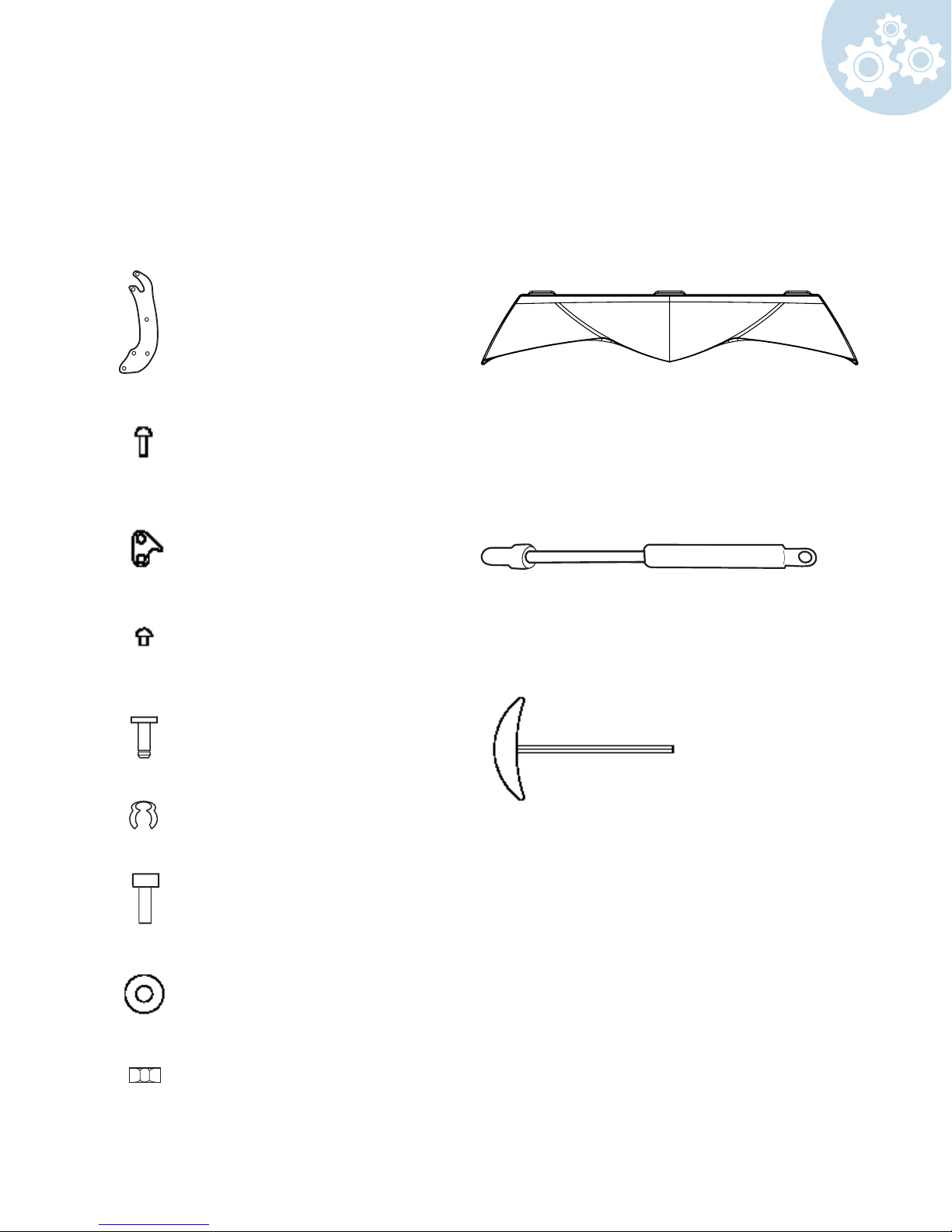
2 Security Plates
FAMS6012236
2 Combi Arms
FAMS6012171
1 Alan Wrench
ACCE1009552
Included Parts
Make sure all parts are included before you begin.
6 Combi Arm Screws
FASN1508828
4 Gas Shock Pivots
GASP9008435
4 Security Clips
GASP90008436
1 Plastic Front Skirt (optional)
bronze - CVPL 6012336
red - CVPL 6513606
white - CVPL 6525156
1 Gas Shock
4 Security Plate Screws
FASN1513151
2 Deco Shield Nuts
FASN3001132
2 Deco Shield Washers
FASN6001362
2 Deco Shield Screws (optional)
black
FASN5010879
10
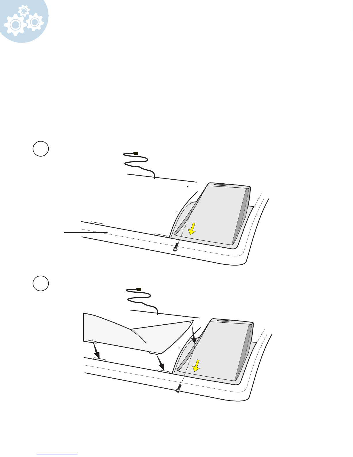
Carefully remove the bench from box and keep it face down.
*Optional Front Skirt (if you do not have a plastic front skirt go to step 3)
Retrieve
1 Plastic front skirt (located in canopy box)
Remove the screw from the leg.
Insert plastic front skirt and screw in place. Repeat these steps on other side.
Assembly
1
2
bench
Table of contents
Other ProSun Tanning Bed manuals

ProSun
ProSun Luxura X3 User manual

ProSun
ProSun V3 User manual

ProSun
ProSun LUXURA X7 User manual

ProSun
ProSun Sundream 12 User manual

ProSun
ProSun Luxura X10/Vegaz 52 User manual

ProSun
ProSun LUXURA V8 User manual

ProSun
ProSun Luxura X10 User manual

ProSun
ProSun Onyx 32 Sli Intensive User manual

ProSun
ProSun Luxura V7 User manual

ProSun
ProSun RenuvaSkin L3200 User manual


