Safety Precaution
Front View Rear View
All Rights Reserved. Copyright 2023
Rear I/O View
•
Do not turn the system upside down. This may cuase the hard drive to mal-function.
4. Good Care
•When the outside of the case is stained, remove the stain with a neutral washing agent with a dry cloth.
•Never use strong agents such as benzene and thinner to clean the system.
•If heavy stains are present, moisten a cloth with diluted neutral washing agent or with alcohol and then wipe thoroughly with a dry cloth.
•If dust has been accumulated on the outside, remove it by using a special vacuum cleaner for computers.
CAUTION! Danger of explosion if battery is incorrectly replaced. Replace only with the same or equivalent type recommended by the
manufacturer. Dispose of used batteries according to the manufacturer’s instructions.
WARNING! Some internal parts of the system may have high electrical voltage. And therefore we strongly recommend that qualified engineers
can open and disassemble the system. Please handle LCD and Touchscreen with extra care as they are easily breakable.
3. Handling
Avoid putting heavy objects on top of the system.
•
•
•
•
•
•
•
•
•
•
The following messages are reminders for safety on how to protect your system from damages and extend a long life of the system.
1. Check the Cable Voltage
The range of operating voltage should be DC 12V/24V. Otherwise, the system could be damaged.
2. Environmental Conditions
Place your SG-S192 / SG-S212 / SG-S232 on a sturdy, level surface. Be sure to allow enough space to have easy access around
the system.
Avoid extremely hot or cold place to install the system.
Avoid exposure to sunlight for a long period of time or in an airtight space.
Avoid the system from any heating device or using the system when it’s been left outdoors in a cold winter day.
Bear in mind that the operating ambient temperature is from 0°C ~ 50°C ((32°F~122°F).
Avoid moving the system rapidly from a hot place to a cold place and vice versa because condensation may come from inside
of the system.
Placing the sy in strong vibrations may cause hard disk failure.
Don’t place the system close to any radio-active device in case of signal interference.
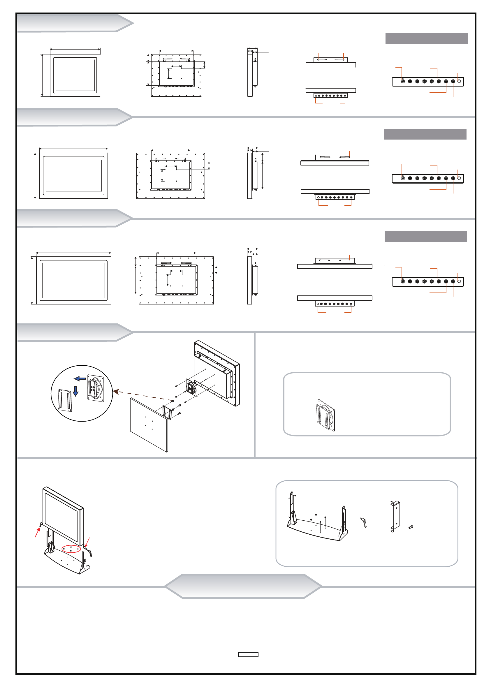
SG-S192 Overview
SG-S212 Overview
SG-S232 Overview
Quick Setup
Installing VESA Mount VESA Mount Accessories
Installing Stand Kit Stand Installation Accessories
(Unit: mm)
Top View
Bottom View
Side View
Front View Rear View Side View Top View
Bottom View
Rear I/O View
Front View Rear View Side View Rear I/O View
Top View
Bottom View
Wall
VESA Mount
VESA Mount Kit x 1
Step 1. Attach Panel PC onto Stand Kit and align the side holes on the rear
of Panel PC with the upper holes of the Stand Kit.
Step 2. Fasten the two handles into the side holes of the Stand Kit
to secure the system and complete.
Stand Kit
Handle
upper hole of
Stand Kit
Stand Kit x 1 + Screw x 4
Handle x 2
Hand Screw Bracket x 2
+ Screw x 4
Hand Screw Bracket
P/N: 20-206-07001527
M4x0.7P screw
P/N: 22-210-40010011
P/N: 20-035-35001000
M4 x 0.7P screw
P/N: 22-240-40020011
VENT
USBLANDC IN LAN USB COM COM
VENT
LAN
LAN
DC IN
Power
Switch
w/LED
2 x USB Connectors
COM1
COM2
(colay Audio)
(colay DIO)
(4 x USB 2.0 Ports)
VENT
USBLANDC IN LAN USB COM COM
VENT
LAN
LAN
DC IN
Power
Switch
w/LED
2 x USB Connectors
COM1
COM2
(colay Audio)
(colay DIO)
(4 x USB 2.0 Ports)
VENT
USBLANDC IN LAN USB COM COM
VENT
LAN
LAN
DC IN
Power
Switch
w/LED
2 x USB Connectors
COM1
COM2
(colay Audio)
(colay DIO)
(4 x USB 2.0 Ports)
ANT ANT
Antenna
Hole
Antenna
Hole
COM
VENT
COM
USB
USB
LAN
LAN
DC IN
I/O Ports
416
488
73.75
C.L.333
233
66.50
C.L.100 (VESA)
100 (VESA)
45.80 95.30
48.50
590
395
92.30
77
233
42.80 48.50
ANT ANT
Antenna
Hole
Antenna
Hole
VENT
COM
COM
USB
USB
LAN
LAN
DC IN
I/O Ports
635
404
ANT
Antenna
Hole
Antenna
Hole
ANT
VENT
COM
COM
USB
USB
LAN
LAN
DC IN
I/O Ports
91.80
42.30 48.50
C.L.333
66.50
C.L.100 (VESA)
100 (VESA)
C.L.333
66.50
81.50
233
C.L.100 (VESA)
100 (VESA)


