Protect 600i Series User manual

NC
NO
COM.
NC
NO
–
+
Fire
Fire
–
+
Disable
–
+
Sec.
–
+
Prim
–
+
Arm
–
12 V
Output
Tamper
Zone Tamper
Alarm System
Disable Signal
Alarm Signal
1
2 V +
Closed ind daytime
Opens with alarm
1
2 V –
1
2 V –
Motion
PIR
Tamper
1
2 V
–
+
+
COM.
NC
NO
COM.
NC
Fog Cannon
Zone Fog
Zone Fault
Zone Fluid
Alarm System
Fog Cannon
Dimensioning
and service guide
Version 1.5
Alarm System
PROTECTGLOBAL.COM
• What must be secured – which valuables? ✔
• Where are the valuables to be secured? ✔
• The design of the room/rooms ✔
• Full coverage ✔
• Point/partial protection? ✔
• The intruders expected actions ✔
• Critical seconds/primary and secondary area ✔
• Fog deployment time in seconds ✔
• Position – Ceiling Mounting – Wall Mounting ✔
• Amount of fog needed ✔
• Choice of machine/machines ✔
• Activation type/types ✔
Dimensioning, Specification
and Positioning - CHECKLIST
DIMENSIONING - CHECKLIST
INSTALLATIONS RECOMENDATION
POINT PROTECTION
FULL PROTECTION
REMEMBER!
Heating time =
Time without coverage.
• PROTECT FOQUS = 7 min.
• PROTECT QUMULUS = 8-10 min.
• PROTECT Xtratus = 8 min.
• PROTECT 600i = 10-15 min.
• PROTECT 1100i = 15-25 min.
• PROTECT 2200i = 30-45 min.
If the heating time is considered too
long, it is recommended to keep the
machine constantly heated.
Point protection in shop
Full protection in shop
Point protection in warehouse
Full protection in shop
HEATING TIME
GOOD INSTALLATION/DEMO BAD INSTALLATION/DEMO
REMEMBER!
Reheating time after deployment of
fog - for full capacity.
• PROTECT FOQUS = 0,5-3 min.
• PROTECT QUMULUS = 0-5 min.
• PROTECT Xtratus = 0-5 min.
• PROTECT 600i = 0-5 min.
• PROTECT 1100i = 0-8 min.
• PROTECT 2200i = 0-14 min.
REHEATING TIME
1. 2.
3. 4.
1
Seen from above Seen from above
Min. 2,5 m.
Min. 2,5 m.
35 cm
1. 1.
3. 3.
2. 2.
4. 4.

DIMENSIONING EXAMPLES
OTHERS
WARNING: Be careful of escape routes and emergency exits!
When placing a Fog CannonTM you shall always be careful that the escape routes are not blocked by the fog.
Stairways and corridors could be part of the escape routes. The Fog CannonTM shall never be installed so that a trap is made.
The Fog CannonTM should always be installed so that the fog is firing into the expected path of the burglar,
so that the burglar is forced back and out.
In general:
The fog output from the PROTECT Fog Cannons®, are defined by the so called ”Industrial standard”, meaning that the visibility in the relea-
sed fog, is app. 1,5m after 60 seconds. Meaning that a Protect 600iTM running for 60 seconds, will produce 700 m3fog. Released in a room of
700 m3, this will give a visibility of 1,5 meter.
The standard EN 50131-8, requires the visibility, after 60 seconds, to be 1 meter.
We recommend, to achieve 1 meter visibility, to have the measured room’s volume multiplied by 2.
Example: a room of 12 x 9 x 3 meter, equal to 108 m2and 324 m3. Twice the volume is 648 m3.
In this case the model 600iTM will be suitable, making 700 m3in 60 sec.
The calculations are only indicative. You need to make a full-scale test to ensure that your dimensioning are correct, and to make sure that
the coverage is satisfying.
LOW VOLTAGE
HIGH VOLTAGE
EXAMPLES
Suggestion for solution 1:
Total protection: 2 x Model 600iTM installed on the celling. Either turbo
function 30 seconds or normal 60 seconds setting. A wish of visibility un-
der 1 meter and fast deployment because of possibility of quick robbery
of Computer equipment.
Need: 1 M visibility: 720 m3fog. 1
/2M visibility: 1440 m3fog. 60 seconds
operation is approximately 1400 m3fog.
Suggestion for solution 3:
Point protection/Total protection: 2 x model 1100iTM, installed on the
celling. 60 seconds setting. Primary coverage around the gates, se-
condary coverage in the back of the warehouse. (Alternative placement
could be 3 meters up on the wall with a 30 degree nozzle. Advantage:
Easier installation and service. Disadvantage: A Risk of the Fog
CannonsTM being placed behind pallets).
Need: 1,5 M visibility: 1080 m3fog. 1 m visibility: 2160 m3fog. 1
/2M visi-
bility: 4320 m3fog. 60 seconds operation is approximately 2600 m3fog.
Suggestion for solution 2:
Total protection: 1 QUMULUS®. No Nozzle. Effort 400 m3in 60 seconds.
Firing time 60 seconds. Visibility under 1 M.
Need: 1 M visibility: 180 m3fog. 1
/2 M visibility: 360 m3fog. 60 seconds
operation is approximately 400 m3fog.
Suggestion for solution 4:
Total protection: 1 Model 1100iTM wall installed on the wall, 30 degree
nozzle, 60 seconds fire time. Primary coverage is in the front of the
shop, secondary at the back of the shop. The fog will move like piston
through the shop. (Alternative 1 x model 2200iTM, same conditions but
with a 30 seconds fire time. Advantage: faster coverage, less risk of
“man trap”.)
Need: 1 M visibility: 1260 m3fog. 1
/2M visibility: 2520 m3fog. 60 seconds
operation is approximately 1300 m3fog.
Suggestion for solution 1:
Suggestion for solution 1:
Office space. Ceiling height 3 meters
120 m2- 360 m3
Warehouse. Ceiling height 4,5 meters
240 m2- 1080 m3
Shop. Ceiling height 3,5 meters
180 m2- 630 m3
Primary
area
Secondary
area
Primary
area Secondary
area
Primary
area
Primary
area
8 m
20 meter
20 m
Port
Port
9 m
15 m12 m
6 meter 4 m
Primary
area
A private living room, ceilingheight 2,5 meter.
Area 36 m2, volume 90 m3
Secondary
area
Secondary
area

SPECIFICATIONS:
Performance (fog generation), examples: 30 sec. TURBO: 600 m³
60 sec.: 700 m³
60 sec. with 9-min. pulse:
1700 m³
Fog generation settings: Can be timed at 3 intervals
from 290–700 m3
Pulse function: Yes, able to shoot several times
Battery backup (2 x 12 V, 1.2 Ah): Backup of electronics and pump
Total capacity (full uid container): Approx. 4800 m3
Fluid container: 1,1 litres
Electronic uid measurement: Yes
Number of 60-sec. shots in one container: 7
Mains connection: 230 V, 50 Hz
Power consumption: 1050 W
Standby consumption after heating up: 60 W (on average)
Standby consumption when heat is disabled: 5-10 W
Heating time from cold: 10-15 min.
Re-heating time after fog discharge: 0–5 min.
Operating temperature (min./max.): 5/80°C.
Input: 5 signals
Output: 3 signals
Control settings for fog time, signals and heating:
On/off DIP switches
Power backup after power failure: Up to 3 hours
Built-in automatic battery testing: Yes
Signals/Indications: Optical, audible and electrical
Status indicator on PCB: Yes
External status indicator: Yes, red/yellow/green LED
Data log memory: Possible with IntelliSuite™
Dimensions (mm): L: 475, W: 332, H: 154
Installation weight: 12.6 kg
4 different angled nozzles and nozzle extension options:
Yes
Available in the following colours: White and black
Tested and approved in accordance with EN 50131-8:
Yes
PROTECT 600iTM
Dip Setting Fog Time Fog Volume
Dip 2 Dip 3 Dip 4 m³
OFF OFF OFF demo -
ON OFF OFF 20s 290
OFF ON OFF 40s 540
ON ON OFF 60s 700
OFF OFF ON 60s + 1 min. 775
ON OFF ON 60s + 4 min. 1050
OFF ON ON 60s + 9 min. 1700
ON ON ON 30s – turbo 600
FOG OUTPUT DIAGRAM
DIP Function
1Heat disable. On = The heating element
disconnects if disable is activated
2 Fog time
3 Fog time
4 Fog time
5 Arm*
6 Primary*
7 Secondary*
8 Fire-alarm delay**
9 Reserved. Leave in OFF position
10 Error indicator. On = Beeper connected
* ON = normal open.
OFF = normal closed.
** ON = delay is active.
DIPSWITCH SETTINGS
TYPICAL
SPARE PARTS
FOG TIME DIP 2-3-4
DISPLAY EXPLANATION
DISPLAY
HHeating. The system is in the heating
phase and has not reached operating
temperature.
rThe system has reached normal operating
temperature and is ready to produce fog.
d”Disable” input activated and system
blocked, as the alarm is not connected
(heating has not been disconnected).
Hd ”Heat Disable”. ”Disable” input activated
and system blocked, as the alarm is not
connected. Heating is also disconnected, as
dipswitch 1 is in the ON position.
bt “Blocking timer active”. System blocked
from fog triggering internally (timer-con-
trolled). This occurs after the fog has been
triggered or in connection with system
start-up after loss of mains voltage.
A“ARM” input activated.
P“Primary Trig” input activated.
S“Secondary Trig” input activated.
bAt A battery is (or has been) mounted.
CThe battery is currently being charged.
E1 Mains voltage failure.
E2 Low uid level.
E3 Fire alarm input activated.
E4 Low battery voltage.
E5 Failed attempts to charge the battery for
24 hours.
E6 Battery failed load test.
E7 PCB temperature too high.
E8 PCB temperature too low.
E9 Thermo-sensor temperature too high (or
connection lost).
E10 Thermo-sensor temperature too low
(after preliminary heating).
E12 Pump timeout. The pump has been running
for too long. Lack of uid, etc.
E13 External 12 supply shut down due to
overload.
E14 Error in “load test circuit”.
White - Item no.: 90010618
Black - Item no.: 90010619
CONSUMER GOODS
90020206 XTRA+Fog fluid 1,1 l
90220430 30 Nozzle
90220403 3-hole nozzle
90020433 30 degree 3-hole nozzle
90020000 Nozlle extension 15 cm
90020500 Ceiling plate
90020500 Hoist tool
SSP1060 Batteri 12V - 1,2Ah
SPP1075-0000 Thermo Sensor
SPP600i-0000 Print
SPP600-0025 Heating Rod
TURBO
Break Break
PROTECT Pulse Effect
TM
60 sec. fog Fog output Fog output Fog outputFog outputFog output
BreakBreakBreak
Display/
fault codes
DISPLAY / FAULT CODES
PrO Ec 600 EU
H. H: Heat
r. r: ready
d. d: disable
H.d. Hd: Heat disable
B. . Bt: Blocking timer
A. A: Arm trig
P. P: Primary trig
S. S: Secondary trig
b.A. . bat: battery
C. C: Charge
E. E: Error + no
1.234567890
1.234568790
rc. rc: Remotely controlled*
norc. norc: No remote control signal*
rd. Remotely disabled*
rHd. rHd: Remotely heat disabled*
rP. rP: Remote primary*
rb. rb: Remotely blocked*
rF. rF: Remote re alarm*
rPA rPA: Remote panic alarm activated*

SPECIFICATIONS:
Performance (fog generation), examples: 60 sec.: 1300 m³
60 sec.: 1300 m³
60 sec.: 1300 m³
Fog generation settings: Can be timed at 4 intervals
from 500–1300 m3
Pulse function: Yes, able to shoot several times
Battery backup (2 x 12 V, 1.2 Ah): Backup of electronics and pump
Total capacity (full uid container): Approx. 4800 m3
Fluid container: 1.1 litres
Electronic uid measurement: Yes
Number of 60-sec. shots in one container: 4
Mains connection: 230 V, 50 Hz
Power consumption: 1350 W
Standby consumption after heating up: 70 W (on average)
Standby consumption when heat is disabled: 5-10 W
Heating time from cold: 15-25 min.
Re-heating time after fog discharge: 0–8 min.
Operating temperature (min./max.): 5/80°C.
Input: 5 signals
Output: 3 signals
Control settings for fog time, signals and heating:
On/off DIP switches
Power backup after power failure: Up to 3 hours
Built-in automatic battery testing: Yes
Signals/Indications: Optical, audible and electrical
Status indicator on PCB: Yes
External status indicator: es, red/yellow/green LED
Data log memory: Possible with IntelliSuite
Dimensions (mm): L: 475, W: 332, H: 174
Installation weight: 16 kg
4 different angled nozzles and nozzle extension options:
Yes
Available in the following colours: White and black
Tested and approved in accordance with EN 50131-8:
Yes
FOG OUTPUT DIAGRAM
TYPICAL
SPARE PARTS
FOG TIME DIP 2-3-4
CONSUMER GOODS
90020206 XTRA+Fog fluid 1,1 l
90220430 30° Nozzle
90020403 3-hole nozzle
90020433 30° degree 3-hole nozzle
90020000 Nozlle extension 15 cm
90020505 Ceiling plate
90020500 Hoist tool
SPP1060 Batteri 12V - 1,2Ah
SPP1075-0000 Thermo Sensor
SPP1100-0025 Heating Rod
SPP1100i-0000 Print
PROTECT 1100iTM
Dip Setting Fog Time Fog Volume
Dip 2 Dip 3 Dip 4 m³
OFF OFF OFF demo demo
ON OFF OFF 15s 500
OFF ON OFF 30s 875
ON ON OFF 45s 1200
OFF OFF ON 60s 1300
ON OFF ON 60s + 4 min.* 1700*
OFF ON ON - -
ON ON ON - -
White - Item no.: 90011118
Black - Item no.: 90011119
DISPLAY EXPLANATION
DISPLAY
HHeating. The system is in the heating
phase and has not reached operating
temperature.
rThe system has reached normal operating
temperature and is ready to produce fog.
d”Disable” input activated and system
blocked, as the alarm is not connected
(heating has not been disconnected).
Hd ”Heat Disable”. ”Disable” input activated
and system blocked, as the alarm is not
connected. Heating is also disconnected, as
dipswitch 1 is in the ON position.
bt “Blocking timer active”. System blocked
from fog triggering internally (timer-con-
trolled). This occurs after the fog has been
triggered or in connection with system
start-up after loss of mains voltage.
A“ARM” input activated.
P“Primary Trig” input activated.
S“Secondary Trig” input activated.
bAt A battery is (or has been) mounted.
CThe battery is currently being charged.
E1 Mains voltage failure.
E2 Low uid level.
E3 Fire alarm input activated.
E4 Low battery voltage.
E5 Failed attempts to charge the battery for
24 hours.
E6 Battery failed load test.
E7 PCB temperature too high.
E8 PCB temperature too low.
E9 Thermo-sensor temperature too high (or
connection lost).
E10 Thermo-sensor temperature too low
(after preliminary heating).
E12 Pump timeout. The pump has been running
for too long. Lack of uid, etc.
E13 External 12 supply shut down due to
overload.
E14 Error in “load test circuit”.
DIP Function
1Heat disable. On = The heating element
disconnects if disable is activated
2 Fog time
3 Fog time
4 Fog time
5 Arm*
6 Primary*
7 Secondary*
8 Fire-alarm delay**
9 Reserved. Leave in OFF position
10 Error indicator. On = Beeper connected
* ON = normal open.
OFF = normal closed.
** ON = delay is active.
DIPSWITCH SETTINGS
Break Break
PROTECT Pulse Effect
TM
60 sec. fog Fog output Fog output Fog outputFog outputFog output
BreakBreakBreak
Display/
fault codes
DISPLAY / FAULT CODES
PrO Ec 600 EU
H. H: Heat
r. r: ready
d. d: disable
H.d. Hd: Heat disable
B. . Bt: Blocking timer
A. A: Arm trig
P. P: Primary trig
S. S: Secondary trig
b.A. . bat: battery
C. C: Charge
E. E: Error + no
1.234567890
1.234568790
rc. rc: Remotely controlled*
norc. norc: No remote control signal*
rd. Remotely disabled*
rHd. rHd: Remotely heat disabled*
rP. rP: Remote primary*
rb. rb: Remotely blocked*
rF. rF: Remote re alarm*
rPA rPA: Remote panic alarm activated*

SPECIFICATIONS:
Performance (fog generation), examples: 60 sec.: 2700 m³
70 sec.: 2875 m³
60 sec. with 10-min. pulse:
3700 m³
Fog generation settings: Can be timed at 4 intervals
from 900-2875 m3
Pulse function: Yes, able to shoot several times
Battery backup (2 x 12 V, 1.2 Ah): Backup of electronics and pump
Total capacity (full uid container): Approx. 13200 m3
Fluid container: 3 litres
Electronic uid measurement: Yes
Number of 60-sec. shots in one container: 5
Mains connection: 230 V, 50 Hz
Power consumption: 1680 W
Standby consumption after heating up: 80 W (on average)
Standby consumption when heat is disabled: 5-10 W
Heating time from cold: 30-45 min.
Re-heating time after fog discharge: 0–14 min.
Operating temperature (min./max.): 5/80°C.
Input: 5 signals
Output: 3 signals
Control settings for fog time, signals and heating:
On/off DIP switches
Power backup after power failure: Up to 3 hours
Built-in automatic battery testing: Yes
Signals/Indications: Optical, audible and electrical
Status indicator on PCB: Yes
External status indicator: Yes, red/yellow/green LED
Data log memory: Possible with IntelliSuite
Dimensions (mm): L: 633, W: 352, H: 172
Installation weight: 24.8 kg
4 different angled nozzles and nozzle extension options:
Yes
Available in the following colours: White and black
Tested and approved in accordance with EN 50131-8:
Yes
FOG OUTPUT DIAGRAM
TYPICAL
SPARE PARTS
FOGTIME DIP 2-3-4
CONSUMER GOODS
90022200 XTRA+Fog fluid 3 l
90022230 30° Nozzle
90022203 3-hole nozzle
90022233 30° degree 3-hole nozzle
90020000 Nozlle extension 15 cm
90020506 Ceiling plate
90020500 Hoist tool
SPP1060 Batteri 12V - 1,2Ah
SPP1075-0000 Thermo Sensor
SPP2200-0025 Heating Rod
SPP2200i-0000 Print
White - Item no.: 90012218
Black - Item no.: 90012219
PROTECT 2200iTM
Dip Setting Fog Time Fog Volume
Dip 2 Dip 3 Dip 4 m³
OFF OFF OFF demo demo
ON OFF OFF 20s 900
OFF ON OFF 40s 1800
ON ON OFF 60s 2700
OFF OFF ON 70s 2875
ON OFF ON 30s + 6 min.* 2500*
OFF ON ON 60s + 10 min.* 3700*
ON ON ON - -
DISPLAY EXPLANATION
DISPLAY
HHeating. The system is in the heating
phase and has not reached operating
temperature.
rThe system has reached normal operating
temperature and is ready to produce fog.
d”Disable” input activated and system
blocked, as the alarm is not connected
(heating has not been disconnected).
Hd ”Heat Disable”. ”Disable” input activated
and system blocked, as the alarm is not
connected. Heating is also disconnected, as
dipswitch 1 is in the ON position.
bt “Blocking timer active”. System blocked
from fog triggering internally (timer-con-
trolled). This occurs after the fog has been
triggered or in connection with system
start-up after loss of mains voltage.
A“ARM” input activated.
P“Primary Trig” input activated.
S“Secondary Trig” input activated.
bAt A battery is (or has been) mounted.
CThe battery is currently being charged.
E1 Mains voltage failure.
E2 Low uid level.
E3 Fire alarm input activated.
E4 Low battery voltage.
E5 Failed attempts to charge the battery for
24 hours.
E6 Battery failed load test.
E7 PCB temperature too high.
E8 PCB temperature too low.
E9 Thermo-sensor temperature too high (or
connection lost).
E10 Thermo-sensor temperature too low
(after preliminary heating).
E12 Pump timeout. The pump has been running
for too long. Lack of uid, etc.
E13 External 12 supply shut down due to
overload.
E14 Error in “load test circuit”.
DIP Function
1Heat disable. On = The heating element
disconnects if disable is activated
2 Fog time
3 Fog time
4 Fog time
5 Arm*
6 Primary*
7 Secondary*
8 Fire-alarm delay**
9 Reserved. Leave in OFF position
10 Error indicator. On = Beeper connected
* ON = normal open.
OFF = normal closed.
** ON = delay is active.
DIPSWITCH SETTINGS
Break Break
PROTECT Pulse Effect
TM
60 sec. fog Fog output Fog output Fog outputFog outputFog output
BreakBreakBreak
Display/
fault codes
DISPLAY / FAULT CODES
PrO Ec 600 EU
H. H: Heat
r. r: ready
d. d: disable
H.d. Hd: Heat disable
B. . Bt: Blocking timer
A. A: Arm trig
P. P: Primary trig
S. S: Secondary trig
b.A. . bat: battery
C. C: Charge
E. E: Error + no
1.234567890
1.234568790
rc. rc: Remotely controlled*
norc. norc: No remote control signal*
rd. Remotely disabled*
rHd. rHd: Remotely heat disabled*
rP. rP: Remote primary*
rb. rb: Remotely blocked*
rF. rF: Remote re alarm*
rPA rPA: Remote panic alarm activated*

SPECIFICATIONS:
FOG OUTPUT DIAGRAM
TYPICAL
SPARE PARTS
FOG TIME DIP 2-3-4
CONSUMER GOODS
90020206 XTRA+Fog fluid 3 l
90020230 30° Nozzle
SPP1060 Batteri 12V - 1,2Ah
SPP1075-0000 Thermo Sensor
SPP200-0020 Heating Rod
SPP200-0000 Print
White - Item no.: 90010201
FOQUSTM
Dip Setting Fog Time Fog Volume
Dip 2 Dip 3 Dip 4
OFF OFF OFF - Do not use
ON OFF OFF - 8 m2 / 72 m2
OFF ON OFF - 16 m2 / 144 m2
ON ON OFF - 25 m2 / 180 m2
OFF OFF ON - 10 sec. of fog + 3 pulse shots (in all about 90 sec. fog)
ON OFF ON - 10 sec. of fog + 6 pulse shots (in all about 180 sec. fog)
OFF ON ON - 6 sec. of fog (full speed) + 294 sec. of fog
(reduced speed). In all 300 sec. fog
ON ON ON - 5 sec. of fog (at normal speed)
+ 5 min. of continuous fog (at very slow speed)
Fog generation: Rooms up to 25 m²
Fog production settings: Three possible durations (8, 16 and 25 m2)
Pulse mode: Yes, can shoot several times (3 settings)
Fog uid container: 1.1 litre (same as model 600TM /600iTM and 1100TM /1100iTM )
Shots per container: Min. 20
Electronic uid measurement: Yes
Mains connection: 230 V, 50 Hz z
Power consumption: 700 W
Standby consumption (after warm up): 55 W
Standby consumption (when heat is disabled): 5 – 10 W
Warm-up time from cold: 7 min.
Warm-up time after fog discharge: ½ – 3 min.
Operation temperature (min./max.): 5/80° C.
Input: 5 signals
Output: 3 signals
Control settings for fog time, signals and heating: On/off DIP switches
Battery back up (2 x 12 V, 1.2 Ah): Electronics and pumps
Power backup after power failure: Up to 1 hour
Built-in automatic battery loading: Yes
Signals/Indicators: Audible, optical, and electrical
PCB status indicator: Yes
Data log memory: Yes, optional with IntelliSuiteTM
Dimensions (mm): L: 400, B: 240, H: 135
Installation weight: 7 kg
Possibility of 2 different angled nozzles: Yes (straight ahead and 30°)
Metal casing colour: White
0 sek. 10 sek. 20 sek. 30 sek.
144
72
0
180
DISPLAY EXPLANATION
DISPLAY
HHeating. The system is in the heating
phase and has not reached operating
temperature.
rThe system has reached normal operating
temperature and is ready to produce fog.
d”Disable” input activated and system
blocked, as the alarm is not connected
(heating has not been disconnected).
Hd ”Heat Disable”. ”Disable” input activated
and system blocked, as the alarm is not
connected. Heating is also disconnected, as
dipswitch 1 is in the ON position.
bt “Blocking timer active”. System blocked
from fog triggering internally (timer-con-
trolled). This occurs after the fog has been
triggered or in connection with system
start-up after loss of mains voltage.
A“ARM” input activated.
P“Primary Trig” input activated.
S“Secondary Trig” input activated.
bAt A battery is (or has been) mounted.
CThe battery is currently being charged.
E1 Mains voltage failure.
E2 Low uid level.
E3 Fire alarm input activated.
E4 Low battery voltage.
E5 Failed attempts to charge the battery for
24 hours.
E6 Battery failed load test.
E7 PCB temperature too high.
E8 PCB temperature too low.
E9 Thermo-sensor temperature too high (or
connection lost).
E10 Thermo-sensor temperature too low
(after preliminary heating).
E12 Pump timeout. The pump has been running
for too long. Lack of uid, etc.
E13 External 12 supply shut down due to
overload.
E14 Error in “load test circuit”.
DIP Function
1Heat disable. On = The heating element
disconnects if disable is activated
2 Fog time
3 Fog time
4 Fog time
5 Arm*
6 Primary*
7 Secondary*
8 Fire-alarm delay**
9 Reserved. Leave in OFF position
10 Error indicator. On = Beeper connected
* ON = normal open.
OFF = normal closed.
** ON = delay is active.
DIPSWITCH SETTINGS
Break Break
PROTECT Pulse Effect
TM
6/10 sec. fog Fog output Fog output Fog outputFog outputFog output
BreakBreakBreak
Display/
fault codes
DISPLAY / FAULT CODES
PrO Ec 600 EU
H. H: Heat
r. r: ready
d. d: disable
H.d. Hd: Heat disable
B. . Bt: Blocking timer
A. A: Arm trig
P. P: Primary trig
S. S: Secondary trig
b.A. . bat: battery
C. C: Charge
E. E: Error + no
1.234567890
1.234568790
rc. rc: Remotely controlled*
norc. norc: No remote control signal*
rd. Remotely disabled*
rHd. rHd: Remotely heat disabled*
rP. rP: Remote primary*
rb. rb: Remotely blocked*
rF. rF: Remote re alarm*
rPA rPA: Remote panic alarm activated*
SPECIFICATIONS:
FOG OUTPUT DIAGRAM
TYPICAL
SPARE PARTS
FOG TIME DIP 2-3-4
CONSUMER GOODS
90020209 XTRA+Fog fluid Bag 0,4 l
90020430 30 degree nozzle
SPP1060 Batteri 12V - 1,2Ah
SPP1075-0000 Thermo Sensor
SPP100-0025 Heating Rod
SPP100-0000 Print
White - Item no.: 90010101
Performance (fog generation): 60 sec.: 400 m3
Fog generation settings: Can be timed at 3 intervals from 140 – 400 m3
Total capacity (full uid bag): 1800 m3
Fluid bag: 0,4 litres
Electronic uid measurement: Yes
Number of 60-sec. shots in one bag: 4
Pulse mode: Yes, can shoot several times (2 sittings)
Mains connection: 230 V, 50 Hz
Power consumption: 1050 W
Standby consumption after heating up: 60 W (on average)
Standby consumption when heat is disabled: 5-10 W
Heating time from cold: 8-10 min.
Re-heating time after fog discharge: 0-5 min.
Operating temperature (min./max.): 5/80° C.
Input: 5 signals
Output: 3 signals
Control settings for fog time, signals and heating:
On/off DIP switches
Battery backup: Yes. Please notice: QUMULUSTM is delivered without batteries
Power backup after mains connection loss: Up to 1 hour (requires batteries,
which are not delivered as standard).
Signals, indicators: Yes, optical, audible and electrical
Status indicator on PCB: Yes
External status indicator: Yes
Data log memory: Yes, export of data possible with IntelliSuiteTM
Dimensions (mm): L: 650 x B: 140 x H: 148
Installation weight: 10 kg
Possibility of 2 different angled nozzles: Yes, straight ahead and 30°
Compatible with PROTECT’s nozzle extension: No
Metal casing colour: White
QUMULUS®
Dip Setting Fog Time Fog Volume
Dip 2 Dip 3 Dip 4 m3
OFF OFF OFF demo -
ON OFF OFF 20s 140
OFF ON OFF 40s 230
ON ON OFF 60s 400
OFF OFF ON 60s + 2 min. 600
ON OFF ON 60s + 4 min. 900
OFF ON ON - -
ON ON ON - -
DISPLAY EXPLANATION
DISPLAY
HHeating. The system is in the heating
phase and has not reached operating
temperature.
rThe system has reached normal operating
temperature and is ready to produce fog.
d”Disable” input activated and system
blocked, as the alarm is not connected
(heating has not been disconnected).
Hd ”Heat Disable”. ”Disable” input activated
and system blocked, as the alarm is not
connected. Heating is also disconnected, as
dipswitch 1 is in the ON position.
bt “Blocking timer active”. System blocked
from fog triggering internally (timer-con-
trolled). This occurs after the fog has been
triggered or in connection with system
start-up after loss of mains voltage.
A“ARM” input activated.
P“Primary Trig” input activated.
S“Secondary Trig” input activated.
bAt A battery is (or has been) mounted.
CThe battery is currently being charged.
E1 Mains voltage failure.
E2 Low uid level.
E3 Fire alarm input activated.
E4 Low battery voltage.
E5 Failed attempts to charge the battery for
24 hours.
E6 Battery failed load test.
E7 PCB temperature too high.
E8 PCB temperature too low.
E9 Thermo-sensor temperature too high (or
connection lost).
E10 Thermo-sensor temperature too low
(after preliminary heating).
E12 Pump timeout. The pump has been running
for too long. Lack of uid, etc.
E13 External 12 supply shut down due to
overload.
E14 Error in “load test circuit”.
DIP Function
1Heat disable. On = The heating element
disconnects if disable is activated
2 Fog time
3 Fog time
4 Fog time
5 Arm*
6 Primary*
7 Secondary*
8 Fire-alarm delay**
9 Reserved. Leave in OFF position
10 Error indicator. On = Beeper connected
* ON = normal open.
OFF = normal closed.
** ON = delay is active.
DIPSWITCH SETTINGS
Break Break
PROTECT Pulse Effect
TM
60 sec. fog Fog output Fog output Fog outputFog outputFog output
BreakBreakBreak
Display/
fault codes
DISPLAY / FAULT CODES
PrO Ec 600 EU
H. H: Heat
r. r: ready
d. d: disable
H.d. Hd: Heat disable
B. . Bt: Blocking timer
A. A: Arm trig
P. P: Primary trig
S. S: Secondary trig
b.A. . bat: battery
C. C: Charge
E. E: Error + no
1.234567890
1.234568790
rc. rc: Remotely controlled*
norc. norc: No remote control signal*
rd. Remotely disabled*
rHd. rHd: Remotely heat disabled*
rP. rP: Remote primary*
rb. rb: Remotely blocked*
rF. rF: Remote re alarm*
rPA rPA: Remote panic alarm activated*

ELECTRICAL INSTALLATION
TYPICAL CONNECTION WITH AFA SYSTEMS
COM.
NC
NO
Fog Rly.
COM.
NC
NO
Fault Rly.
COM.
NC
NO
Fluid Rly.
–
+
Fire
–
+
Disable
–
+
Sec.
–
+
Prim
–
+
Arm
–
12 V
Output
Tamper
Fog CannonTM
Zone Fog
Zone Fault
Zone Fluid
Zone Tamper
Alarm System
Disable Signal
Alarm Signal
12 V +
Closed in daytime
Opens with alarm
12 V –
12 V –
+
Motion
VERIFYING PIR
Tamper
12 V
–
+
Recommended NC (normal closed) circuit
STATUS: ALARM IS OFF (DAYTIME), FOG CANNONTM IS DISABLED
• Galvanic isolated
• Nominal 12V – 5 mA
• Inputs must be polarized correctly
• Inputs can be connected with 24V by connecting a
resistance in series with the signal (2.4 Kohm)
Logic diagram Input configuration
Dip 8
5 sec. delay
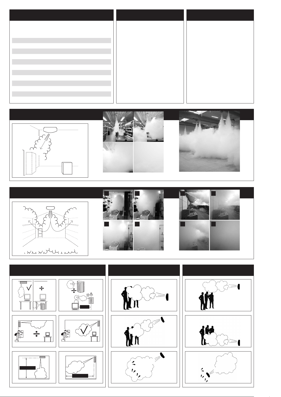
Setup PROTECT IntelliSuiteTM
• Install Driver to IntelliConnectorTM (cable)
• Install IntelliSuiteTM (Software) from PROTECTTM Download
Center
• Connect the IntelliConnectorTM (Cable) to the Fog CannonTM
• Choose communications port
• Setup is normally only necessary once per laptop
• The Cable has a build in 3kV galvanic seperation
to ensure the Fog CannonTM and the laptop
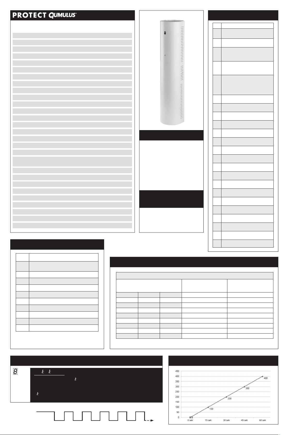
System Monitor
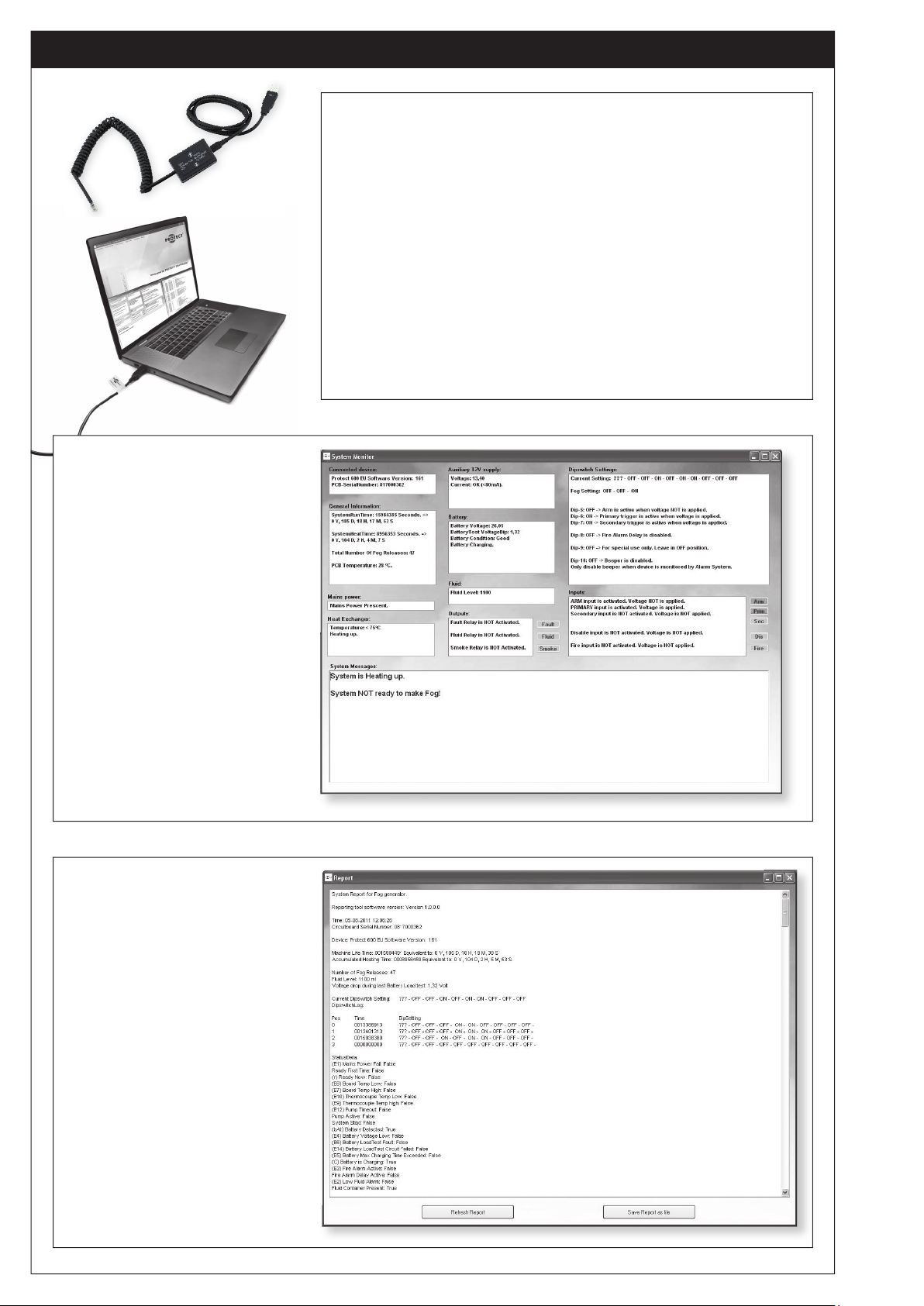
Report tool
• Faults and reasons
• Condition on indputs and outputs
• Batteri condition
• Fluid level
• Operating time
• Dipswitch settingsguide
(fog time)
• All information in one text file
• Saves the last known
dipswitch settings
• Shows faults
• Status on inputs
• Status on outputs
• Analog values

SPECIFICATIONS:
DIP Function
1
Heat disable
On = The heating element disconnects
if disarm is activated
OFF = Constantly heating
2Trig 1*
3Trig 2*
4Reserved.
Leave in OFF position
5Error indicator/buzzer
ON = Beeper/buzzer connected
* ON = Normal open.
OFF = Normal closed.
FOG OUTPUT DIAGRAM
TYPICAL INSTALLATION 8 DIFFERENT ERRORS
FOG TIMEDIPSWITCH SETTINGS
DISPLAY EXPLANATION
GREEN LIGHT
Flashes when heating (1 ash/sec.).
Lights constantly when Xtratus®is Ready.
Turns off if error occurs.
YELLOW LIGHT
Flashes at E2 error (no uid),
beeper sounds and fault relay active
(1 ash/sec.).
Flashes for 24 hours after
successful fog release.
1 ash/sec. (no beeper active).
(Can be erased by pushing Reset button).
RED LIGHT
Lights constantly at critical errors:
E5, E6, E7, E8.
1 ash/sec. at less critical errors:
E1, E3, E4.
CONSUMER GOODS
90020202 Fog fluid 0,4 l
White - Item no.: 90010013
Prepared for 0,4 l. uid container (not included)
Enough uid for 2 discharges in one uid container
Power consumption: 1050 W
Mains connection: 230V, 50 Hz
Standby consumption after heating up: 60 W (on average)
Standby consumption when heat is disabled: 5-10 W
Heating time from cold: 8 min.
Re-heating time after fog discharge: 0-5 min.
Operating temperature (min./max.): 5/80° C.
Input: 3 signals (arming, trig 1, trig 2)
Output: 2 signals
Output power for veri cation sensor (PIR), 9V DC
On/off dipswitches for setting of signals and heating
Backup of electronics (9V Alcaline)
Power backup after power failure: 17 min.
Optical, audible and electrical signals/indicators
Internal and external status indicator
Anti-sabotage, impact-resistant steel casing
Colours available: White
Dimensions: L: 650, W: 140, H: 148 mm
Installation weight: 10 kg
Xtratus®230V
& 115/130V
250 m3at 1 meter visibility.
0 Sec.
275
250
225
200
175
150
125
100
75
50
25
0
4 Sec. 8 Sec. 12 Sec. 16 Sec.
Output 1
Output 2
Arm
Trig 1
Trig 2 12V Out
-
+
9V
-
+
PIR
Movement Detector
Alarm panel
Fog Cannon
Xtratus
Alarm trig
Normally Open
when alarm system
is ARMED (Night)
Closed when alarm
system is disARMED
(day)
-
+
9V Out
E1: Mains supply error
E2: No uid error
E3: Battery voltage low
E4: PCB board temperature high/low error
E5: Thermal sensor error
E6: Heat rod error
E7: Over temperature on heater error
E8: Motor error
Which error is announced?
To nd out which error is announced on the Xtratus®, you simply press
and release the Reset button shortly.
Immediately after, the Xtratus®will tell you which error is present - simply
by counting the present error. This is done by use of the red light and the
buzzer that will ash and beep the error number.
An example: E5 error is present on the Xtratus®. You press and release
the Reset button and the constant red light will turn off. Then the red
light slowly will ash 5 times and the buzzer will sound accordingly.
Right after the red constant light comes back.
So you simply count the number of ashes and beeps, and this will
correspond to the present error number.
This procedure can be repeated until you reset the error.
Fog CannonTM
Xtratus®

PROTECT A/S is the world’s largest supplier and the only producer of fog cannons in Scandinavia.
PROTECTTM is represented worldwide in 50 countries.
GB
PROTECT A/S · Hasselager Centervej 5 · DK-8260 Viby J · Tel.: (+45) 86 72 18 81 · Fax: (+45) 86 72 18 82 · Mail: [email protected]
PROTECTGLOBAL.COM
Other manuals for 600i Series
3
This manual suits for next models
5
Table of contents
Other Protect Fog Machine manuals


