Protect 600i Series User manual
WWW.PROTECTGLOBAL.COM
Installation Manual
Manuel d’installation
Manuale installatore
Manual de la instalación
Installationsmanual
F
I
E
GB
DK
Installation Manual
Version 4.7
PROTECT 600i™, 1100i™, 2200i™
2
Table of contents
1. Begin here – very important if you are installing a Fog CannonTM for the rst time
Please read the installation manual . . . . . . . . . . . . . . . . . . . . . . . . . . . . . . . 4
Removal of cover ........................................... 4
Mounting the brackets ........................................ 5
Positioning ............................................... 6
Safety instructions .......................................... 7
Cabling .................................................. 8
2. Connections, setting and test
Printed circuit board ......................................... 9
Typical installations .........................................10
Dipswitch ................................................12
Inputs...................................................12
Fog volume ...............................................13
Connecting the batteries ......................................15
Installationoftheuidcontainer ................................15
Test ....................................................15
3. Hand over
Information and registration ...................................16
Service and maintenance agreement ..............................17
4. In case of faults
Faultnding ..............................................19
Fuses ...................................................19
Status indicators/fault codes ...................................20
5. Warnings . ..................................................22
Tables des matières
1. Important – si vous installez pour la première fois un générateur de fumée
Lisez s’il vous plait le manuel d’installation.......................... 4
Démontage du capot ......................................... 4
Montagedusupportdexation ................................. 5
Emplacement ............................................. 6
Instructions de sécurité . . . . . . . . . . . . . . . . . . . . . . . . . . . . . . . . . . . . . . . 7
Câblage ................................................. 8
2. Connections, réglages et tests
Carte à circuit imprimé ....................................... 9
Installation type ............................................10
Dipswitch ................................................12
Entrées..................................................12
Volume de fumée ...........................................13
Branchement de la batterie ....................................15
Installer le réservoir .........................................15
Essai ...................................................15
3. Remise
Information et enregistrement ..................................16
Recommandations de Service et de Maintenance ......................17
4. En cas de défauts
Rechercher les défauts .......................................19
Fusibles .................................................19
Indicateurs d’état/codes erreur .................................20
5. Avertissements ...............................................22
Indice
1. Importante – per chi installa un generatore di nebbia per la prima volta
Consultazione del manuale..................................... 4
Apertura del contenitore ...................................... 4
Montaggio delle staffe ........................................ 5
Posizionamento ............................................ 6
Sicurezza ................................................ 7
Cablaggio ................................................ 8
2. Collegamenti, impostazioni e test
Circuito stampato ........................................... 9
Installazioni tipiche..........................................10
Dipswitch ................................................12
Ingressi..................................................12
Volume della nebbia .........................................13
Collegamento delle batterie ....................................15
Installazione del contenitore del liquido ............................15
Test ....................................................15
3. Consegna dell’impianto
Informazione e registrazione....................................16
Contratto di manutenzione.....................................17
4. In caso di funzionamento anomalo
Identicazioneerrore ........................................19
Fusibili . . . . . . . . . . . . . . . . . . . . . . . . . . . . . . . . . . . . . . . . . . . . . . . . . .19
Display e codici errore........................................20
5. Avvertenze .................................................22
F
I
GB
INDEPENDENTLY
TESTED AND GAINED
EN 50131-8
E
U
R
O
P
E
A
N
S
T
A
N
D
A
R
D
O
F
C
R
I
M
E
P
R
E
V
E
N
T
I
O
N
W
I
T
H
S
E
C
U
R
I
T
Y
F
O
G
D
E
V
I
C
E
S
EUROPEAN STANDARD
CONFORME
Á LA NORME
EN 50131-8
NORME EUROPÈENNE
N
O
R
M
E
E
U
R
O
P
É
E
N
N
E
P
O
U
R
L
E
S
C
A
N
O
N
S
À
F
U
M
É
E
A
N
T
I
-
I
N
T
R
U
S
I
O
N
QUESTO PRODOTTO
È CONFORME CON LO
EN 50131-8
S
T
A
N
D
A
R
D
E
U
R
O
P
E
O
P
E
R
I
S
I
S
T
E
M
I
D
I
S
I
C
U
R
E
Z
Z
A
N
E
B
B
I
O
G
E
N
A
STANDARD EUROPEO
Vignet_I_tryk.pdf 1 07/10/11 17.49
PROTECT 600i™, 1100i™, 2200i™3
Contenido
1. Empezar por aquí – importante si es su primera instalación de un generador de niebla
Por favor lea detenidamente el manual de instalación................... 4
Retire las cubiertas ......................................... 4
Montaje de los anclajes ....................................... 5
Colocación ............................................... 6
Instrucciones de seguridad .................................... 7
Cableado ................................................ 8
2. Conexiones, conguración y prueba
Placa de circuito impreso (PCB).................................. 9
Instalación típica ...........................................10
Dipswitch ................................................12
Entradas .................................................12
Volumen de niebla ..........................................13
Conexióndelabatería .......................................15
Se instala el recipiente .......................................15
Prueba ..................................................15
3. Entrega
Información y registro .......................................16
Acuerdo de servicio y mantenimiento ..............................17
4. En caso de averías
Comprobación de la avería .....................................18
Fusibles .................................................19
Indicadores de estado/códigos de avería ...........................20
5. Advertencias . ...............................................22
Indholdsfortegnelse
1. Start her – Særlig vigtigt, når du monterer første gang
Start med at læse manualen.................................... 4
Afmontering af kabinet ....................................... 4
Montering, beslag og mål ...................................... 5
Placering ................................................ 6
Sikkerhedsinstrukser ......................................... 7
Kabelføring ............................................... 8
2. Tilslutning, indstillinger og test
Printkort ................................................. 9
Typisk installation...........................................10
Dipswitche/tågetider ........................................12
Indgange, oversigt ..........................................12
Tågevolumen ..............................................13
Tilslutning af batterier........................................15
Montering af væskedunk ......................................15
Test ....................................................15
3. Aevering
Information og registrering ....................................16
Serviceaftale ..............................................17
4. I tilfælde af fejl
Fejlnding................................................19
Sikringer .................................................19
Statusindikatorer/fejlkoder ....................................20
5. Advarsler . .................................................22
DK
E
ESTE PRODUCTO ES
CONFORME CON LA
EN 50131-8
N
O
R
M
A
E
U
R
O
P
E
A
S
O
B
R
E
P
R
E
V
E
N
C
I
Ó
N
M
E
D
I
A
N
T
E
N
I
E
B
L
A
D
E
S
E
G
U
R
I
D
A
D
NORMA EUROPEA
OPF Y LDER
NORMEN
EN 50131-8
FOR TÅGESIKRING
E
U
R
O
P
Æ
I
S
K
N
O
R
M
F
O
R
T
Y
V
E
R
I
S
I
K
R
I
N
G
M
E
D
T
Å
G
E
K
A
N
O
N
E
R

PROTECT 600i™, 1100i™, 2200i™
4
1.
Begin here - very important if you are installing a Fog CannonTM for the rst time
F: Commencez ici – Particulièrement important quand vous installez un canon à fumée pour la première fois
I: Importante: per chi installa un generatore di nebbia per la prima volta
E: Empezar por aquí – importante si es su primera instalación de un generador de niebla
DK: Start her – Særlig vigtigt, når du monterer første gang
As an installer you must participate in a
PROTECTTM training session.
Avant l’installation, les installateurs doivent suivre
les cours techniques de PROTECTTM.
Suggeriamo la partecipazione ad un corso di
Formazione organizzato da PROTECT
TM
ITALIA
Como instalador, debe participar en un curso de
capacitación de PROTECTTM.
Som installatør skal du have deltaget i et PRO-
TECTTM træningskursus.
F
I
E
DK
GB 1
When unpacking the Fog CannonTM please read the
installation manual carefully.
Quand vous déballez l’appareil, lisez s’il vous plait le
manuel d’installation avec attention.
Leggere attentamente il manuale installatore prima di
iniziare l’installazione.
Antes de desembalar el equipo, por favor lea
detenidamente el manual de instalación.
Før du pakker tågekanonen ud, bedes du læse installa-
tionsmanualen omhyggeligt.
F
I
E
DK
GB 2
Removal of cover.
Démontage du capot.
Rimozione del coperchio.
Retire las cubiertas.
Afmontering af kabinet.
F
I
E
DK
GB 3
PROTECT 600i™, 1100i™, 2200i™5
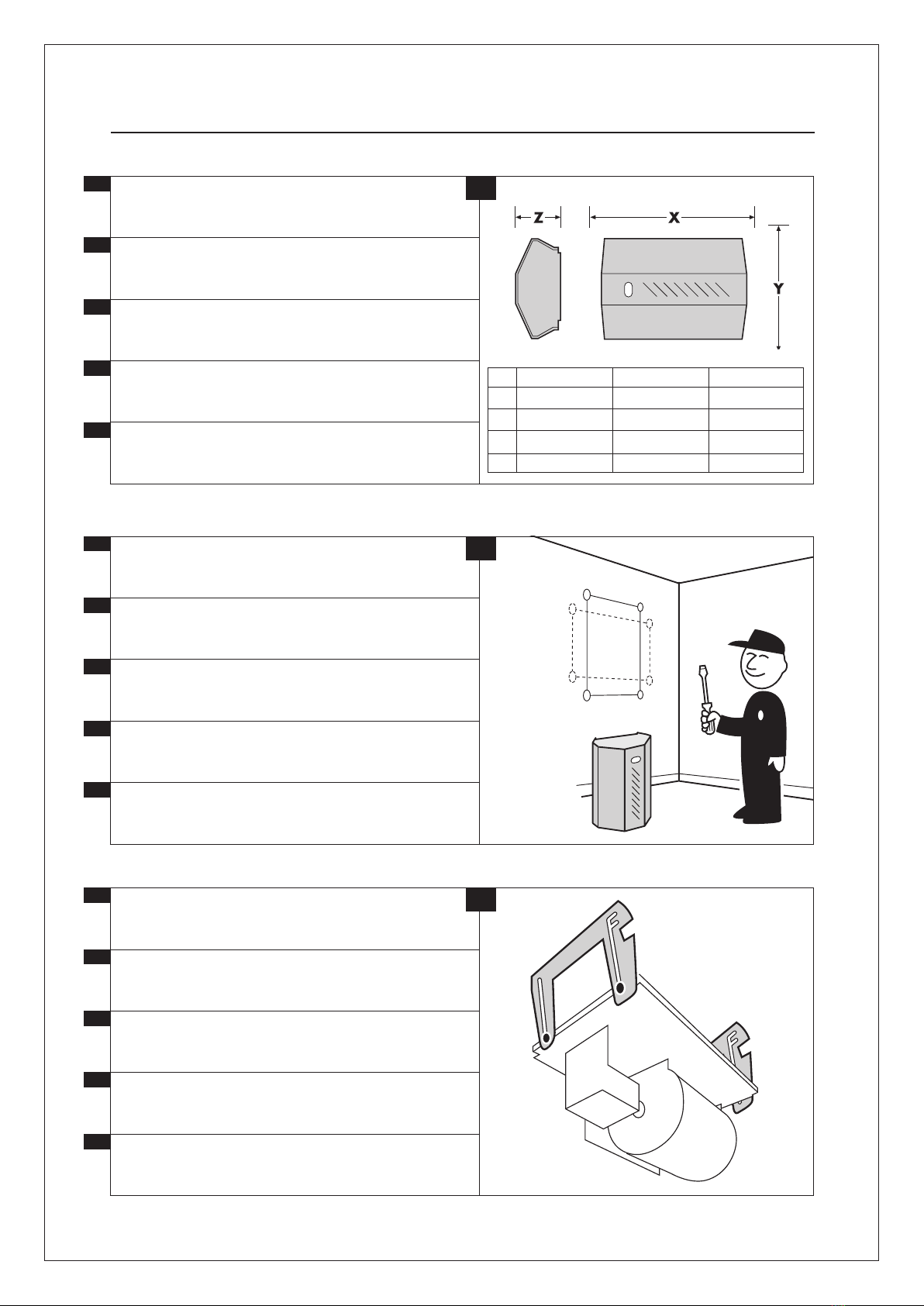
Measurements for installation of the Fog CannonTM.
Dimensions du générateur de fumée lors du montage.
Dimensioni del generatore nebbiogeno.
Medidas del generador de niebla.
Tågekanonens ophængsmål.
F
I
E
DK
GB 4
Mounting the brackets. Use enclosed template.
Montagedusupportdexation.Utilisezlegabarit
fourni.
Montaggio delle staffe. Utilizzare la dima in dotazione.
Montaje de los anclajes. Use plantilla adjunta.
Montering af beslag. Brug vedlagte skabelon.
F
I
E
DK
GB 5
During the installation the generator hangs on the 4
screws before it is pushed into position.
Pendant l’installation, le générateur est suspendu
entre 4 supports avant qu’il soit poussé dans sa position
nale.
Durante l’installazione il generatore rimane appeso
alle 4 viti. Ultimati i collegamenti, spingerlo nella posizio-
nedenitivadilavoro.
Durante la instalación, el generador colgará de los 4
tornillos antes de ser colocado en su posición.
Under installationen hænger maskinen i 4 skruer,
inden den skubbes helt på plads.
F
I
E
DK
GB 6
PROTECT 600iTM
475 mm
332 mm
154 mm
12,6
PROTECT 1100iTM
475 mm
332 mm
174 mm
16
PROTECT 2200iTM
633 mm
352 mm
172 mm
24,8
X
Y
Z
KG

PROTECT 600i™, 1100i™, 2200i™
6
To ensure the best possible coverage the fog needs
free passage.
Pour assurer une couverture optimale, la fumée doit
êtreexpulséesansencombre.
Il generatore di nebbia deve essere posizionato in modo
da coprire istantaneamente i beni da proteggere.
Para asegurar una cobertura óptima, es importante
que la niebla circule libremente al dispararse.
For at sikre bedst mulig dækning skal tågen affyres,
så den har et frit forløb.
F
I
E
DK
GB 7
Prevent sabotage by installing the Fog CannonTM
correctlyoutofreachandavoidblockingexitroutes.
Eviter les risques de sabotage en installant le généra-
teur correctement hors de portée; ne pas couvrir les
voies de fuite.
Evitate la possibilità di sabotaggio installando il generatore
di nebbia fuori portata. La nebbia non deve ostruire le vie di
fuga
Evite la posibilidad de sabotaje mediante una
instalación correcta y fuera de alcance, y evite cubrir
las posibles vías de escape.
Undgå sabotagemulighed ved korrekt montage uden
forrækkeviddesamtundgåatdækkeugtveje.
F
I
E
DK
GB 9
30°
The Fog CannonTM must be placed to ensure
immediate coverage of possible access points
Placer le générateur de fumée de façon à couvrir
immédiatement toute voie d’accès.
Per assicurare una buona copertura, la nebbia non deve in-
contrare ostacoli. Sono disponibili vari ugelli per l’emissione
della nebbia con inclinazioni e direzioni diverse.
El generador de niebla debe colocarse de manera que las
posibles vías de acceso se cubran inmediatamente.
Tågekanonen placeres, så mulige adgangsveje
dækkes øjeblikkeligt.
F
I
E
DK
GB 8

PROTECT 600i™, 1100i™, 2200i™7
Min.35 cm.
Min. installation distance from objects.
Ecart minimal entre le générateur et d’autres
objets.
Distanza minima per ottenere un buon effetto.
Distancia de instalación mín. respecto a otros objetos.
Min. installationsafstand til genstande.
F
I
DK
E
GB
For horizontal mounting, place the Fog CannonTM
as shown in the picture.
Montage horizontal: installer le générateur de fumée
comme illustré.
Posizionamento corretto e distanze minime da pareti e
softti.
En caso de montaje horizontal, el generador de niebla
debe colocarse tal como aquí se indica.
Ved horisontal montage placeres tågekanonen som
vist her.
F
I
E
DK
GB 11
Min. safety distance
– risk of scalding.
Distance de sécurité minimum
– danger d’échaudage.
Distanza minima di sicurezza
- ATTENZIONE: pericolo ustione.
Distancia de seguridad mínima
– peligro de quemaduras.
Min. sikkerhedsafstand
- fare for skoldning.
F
I
E
DK
GB 12
10

PROTECT 600i™, 1100i™, 2200i™
8
Avoid unintentional fog emission
–removetheuidcontainerduringinstallation.
Enlever le réservoir de liquide pendant le montage
pour éviter toute émission de fumée.
Togliereilcontenitoredeluidodurante
l’installazione per evitare la generazione acciden-
tale di nebbia.
Evite los disparos accidentales – retire el recipiente
de líquido durante la instalación.
Undgå utilsigtet affyringer
– fjern væskedunken under montage.
F
I
E
DK
GB
Cabling of PROTECT 600iTM/1100iTM/2200iTM.
Câblage par PROTECT 600iTM/1100iTM/2200iTM.
Cablaggio del sistema
PROTECT 600iTM/1100iTM/2200iTM.
Collegamento al sistema d’allarme.
Cableado del sistema PROTECT 600iTM/1100iTM/2200iTM.
Kabelføring af PROTECT 600iTM/1100iTM/2200iTM.
F
I
DK
E
GB 14
Cabling of PROTECT 600iTM/1100iTM/2200iTM.
Câblage par PROTECT 600iTM/1100iTM/2200iTM.
Cablaggio del sistema
PROTECT 600iTM/1100iTM/2200iTM.
Collegamento alla rete di alimentazione elettrica.
Cableado del sistema PROTECT 600iTM/1100iTM/2200iTM.
Kabelføring af PROTECT 600iTM/1100iTM/2200iTM.
F
I
E
DK
GB 15
13
LOW VOLTAGE
HIGH VOLTAGE
PROTECT 600i™, 1100i™, 2200i™9
2. Connections, setting and test
F: Connections, réglages et tests
I: Collegamenti, impostazioni e test
E: Conexiones,conguraciónyprueba
DK: Tilslutning, indstillinger og test
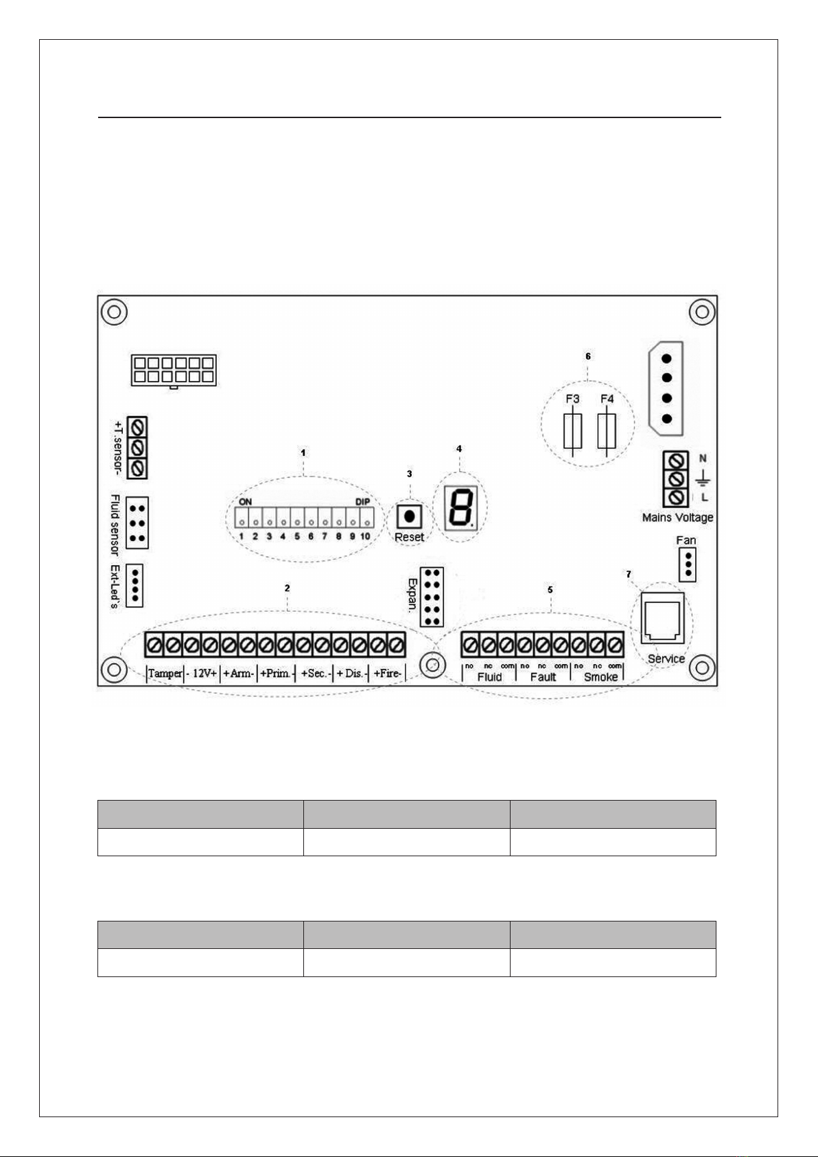
GB: Printed circuit board F: Carte à circuit imprimé (PCB) I: Circuito stampato
E: Placa de circuito impreso (PCB) DK: Printkort
GB: Voltage F: Tension I: Alimentazione E: Tensión DK: Spænding
PROTECT 600i™PROTECT 1100i™PROTECT 2200i™
230 V ac 230 V ac 230 V ac
GB: Effect F: Effet I: Assorbimento E: Consumo DK: Effekt
PROTECT 600i™PROTECT 1100i™PROTECT 2200i™
1050 W 1350 W 1680 W

PROTECT 600i™, 1100i™, 2200i™
10
GB: Typical Installation
F: Installation type
I: Installazione tipica
E: Instalación típica
DK: Typisk Installation
Fog Generator
Service
Fog Rly.
Fault Rly.
Fluid Rly.
COM.
NC
NO
COM.
NC
NO
COM.
NC
NO
Fire
Disable
Sec.
Prim.
ARM
12V
Output
Tamper
–
+
–
+
–
+
–
+
–
+
ON
OFF
1 10
Service Switch
PIR
Alarm System
Zone Fog
Zone Fault
Zone Fluid
Zone Tamper
Zone Swich Position
Disable Signal
Contact Closed During Daytime
Alarm Signal
Contact closes when alarm is tripped
+ 12V
+ 12V
Gnd
Dipswitch
Motion
Tamper
12V
–
+
–
+
PRIMARY TRIGGER NORMALLY OPEN
GB: Connection to alarm
panel (typical installa-
tion)
Primary trigger is NO
(normal open) and
a service switch is
installed.
F: Connexionautableau
d’alarme (installation
type).
Lessignauxde
déclenchement
primaires sont NO
(normalement ouverts)
et un commutateur de
service est installé.
I: Connessione alla cen-
trale di allarme.
I segnali di attivazione
sono in tensione 12 Volt
di tipo NA (normal-
mente assenti).
E: Conexiónalpanelde
alarma (instalación
típica).
Las señales de acti-
vación primarias son
del tipo NA (normal-
mente abierto) y hay
un interruptor de
servicio instalado.
DK: Tilslutning til alarm-
panel (typisk installa-
tion).
Primær trigger signaler
er NO (normal open),
og serviceafbryder er
installeret.

PROTECT 600i™, 1100i™, 2200i™11
GB: Typical Installation
F: Installation type
I: Installazione tipica
E: Instalación típica
DK: Typisk Installation
GB: Connection to
alarm panel (typi-
cal installation).
All triggers are NC
(normal closed).
F: Connexionau
tableau d’alarme
(installation type).
Touslessignaux
de déclenchement
sont NC (normale-
ment fermés).
I: Connessione alla
centrale di al-
larme. I segnali di
attivazione sono in
tensione 12 Volt di
tipo NC (normal-
mente presenti).
E: Conexiónalpanel
de alarma (insta-
lación típica). To-
das las señales de
activación son del
tipo NC (normal-
mente cerrado).
DK: Tilslutning til
alarmpanel (typisk
installation). Alle
trigger signaler
er NC (normal
closed).
Fog Generator
Service
Fog Rly.
Fault Rly.
Fluid Rly.
COM.
NC
NO
COM.
NC
NO
COM.
NC
NO
Fire
Disable
Sec.
Prim.
ARM
12V
Output
Tamper
–
+
–
+
–
+
–
+
–
+
–
+
ON
OFF
1 10 PIR
Alarm System
Zone Fog
Zone Fault
Zone Fluid
Zone Tamper
Disable Signal
Contact Closed During Daytime
Alarm Signal
Contact opens when alarm is tripped
+ 12V
+ 12V
Gnd
Dipswitch
Motion
Tamper
12V
–
+
ALL TRIGGER SIGNALS NORMALLY CLOSED
PROTECT 600i™, 1100i™, 2200i™
12
1. GB: Dipswitch F: Dipswitch I: Dipswitches E: Dipswitch DK: Dipswitch
DIP GB: Function F: Fonction I: Funzione E: Función DK: Funktion
1Heat disable
On = The heating element dis-
connects if disable is activated
Chauffage désactivé
On = l’élément chauffant s’éteint
si “disable” est activé
ON = l’elemento termico è
disattivato quando è attivo il
comando “disable”.
Lasciare in posizione OFF
Desactivar calentamiento
ON = el elemento térmico
se desconecta
Heat disable
ON = varme afbrydes,
når disable aktiveres
2Fog time Durée de la fumée Temporizzazione
emissione nebbia Tiempo de niebla Tågetid
3Fog time Durée de la fumée Temporizzazione
emissione nebbia Tiempo de niebla Tågetid
4Fog time Durée de la fumée Temporizzazione
emissione nebbia Tiempo de niebla Tågetid
5Arm* Arm* Arm* Arm* Arm *
6Primary* Primaire* Primario* Primario* Primær *
7Secondary* Secondaire* Secondario* Secundario* Sekundær *
8Fire-alarm delay** Temporisation de l’avertisseur
d’incendie** Ritardo allarme incendio** Retraso alarma incendio** Brandmelder forsinkelse **
9Reserved. Leave in OFF position Réservé.
Doit rester sur la position OFF
Riservato.
Lasciare in posizione OFF
Reservado. Mantener en posición
OFF
Reserveret.
Sættes i OFF position
10 Error indicator
On = Beeper connected
Détection d’erreur
On = bipeur activé
Segnalatore di errore
ON = buzzer inserito
Indicador de fallo
On = sonido conectado
Fejlmelder
ON = lydgiver tilkoblet
* ON = normal open / normal ouvert / normalmente assente / normal abierta / aktiv slutte.
OFF = normal closed / normalement fermé / normalmente presente / normal cerrada / aktiv bryde.
** ON = delay is active / retraso activo / ritardo attivo / retraso se activa / forsinkelse aktiv.
GB: Inputs F: Entrées I: Ingressi E: Entradas DK: Indgange
GB F I E DK
Tamper
Potential-free switches activate
(open) when the covers are re-
moved. They can be used in the
alarm system’s tamper circuit.
Des contacts libres sont installés
et sont activés (ouverts) lorsque
les couvercles sont enlevés.
Ils peuvent être utilisés dans
le circuit tamper du système
d’alarme.
I contatti puliti si attivano
(aprono) alla rimozione del co-
perchio. Si possono collegare
al circuito antisabotaggio del
sistema di allarme.
Las conexiones libres de po-
tencial se activan (se abren) al
desmontarse las tapas y pueden
emplearse en el circuito tamper
de la instalación de alarma.
Der er monteret potentiale-
fri kontakter, som aktiveres
(åbner), når dækslerne af-
monteres. Disse kan benyttes
i alarmanlæggets tamper
kreds.
12V
Built-in 12V supply system that
delivers 0.1A – mainly to supply
the secondary circuit, e.g. a PIR
sensor.
Alimentation 12V intégrée qui
peut fournir 0,1A principalement
pour alimenter le circuit secon-
daire, tel qu’un capteur PIR.
Alimentazione 12V 0,1 A per ali-
mentare il circuito secondario,
ad esempio un sensore IR come
sensore di verica, o da utiliz-
zare nel caso manchi il comando
12 Volt dal sistema d’allarme e
sia solo disponibile un comando
relè
Alimentación de 12V para sumi-
nistro de 0.1A al circuito secun-
dario, p. ej. un sensor PIR.
Indbygget 12V forsyning, som
kan levere 0.1A til hovedsage-
ligt at forsyne sekunddærkred-
sen, eks. en PIR-sensor.
ARM
Can be activated permanently by
selecting an active break signal
and by not connecting anything
to the terminals.
Peut être activé en permanence
en choisissant comme signal un
signal d’interruption actif et en
évitant de connecter quoi que ce
soitauxbornes.
Può essere attivato permanente-
mente impostandolo come seg-
nale di interruzione attiva e non
collegandoci nulla ai terminali.
Se activa permanentemente se-
leccionando la señal como señal
de ruptura activa sin conectar
nada a los bornes.
Kan aktiveres permanent ved
at vælge signalet som et ak-
tivt bryde signal og undlade at
forbinde noget til klemmerne.
Pri-
mary
The primary trigger signal is
normally taken from the alarm
system and activated from it in
case of a break-in.
Le signal de déclenchement pri-
maire se fait, en règle générale,
à partir du système d’alarme qui
l’active en cas d’effraction.
Il segnale di attivazione pri-
maria è derivato dalla cen-
trale d’ allarme quando rileva
un’intrusione.
Generalmente, la señal de ac-
tivación primaria procede del
sistema de alarma y se activa
desde aquí en caso de robo.
Det primære udløsesignal
tages som en hovedregel fra
alarmsystemet og aktiveres
herfra ved indbrud.
Sec.
The secondary trigger signal is
normally taken from a verifying
sensor such as a room sensor or a
door switch.
Le signal de déclenchement
secondaire se fait normalement
à partir d’un capteur de véri-
cation tel qu’un détecteur de
mouvement ou d’un contact de
porte.
Generalmente il segnale di at-
tivazione secondaria è derivato
da un sensore volumetrico della
stanza protetta (doppio con-
senso per attivare il generatore
di nebbia).
Normalmente, la señal de acti-
vación secundaria procede de un
sensorvericador,p.ejunsensor
de sala o un contacto de puerta.
Det sekundære udløsesignal
tagesnormaltfraenvericer-
ende sensor såsom rumføler
eller en dørkontakt.
DIS.
The disable function can be used
to stop the Fog CannonTM when
it is producing fog. The signal is
connected to the alarm, so the
Fog CannonTM is disconnected
when the alarm is disconnected.
“Disable” peut être utilisé pour
arrêter le générateur de fumée
lorsque celui-ci est en train
d’émettre de la fumée. Le signal
est relié à l’alarme de telle sorte
que le générateur de fumée est
désactivé lorsque l’alarme est
désactivée.
Questo comando blocca la gen-
erazione di nebbia mentre la
macchina è attiva e quando il
sistema d’allarme non è inserito
(locali occupati)
La función desactivar puede
emplearse para detener el
generador de niebla. La se-
ñal se conecta a la alarma de
manera que cuando la alarma
está desconectada, el genera-
dor de niebla también queda
desconectado.
Disable bruges til at stoppe
tågekanonen, når den er i gang
med at producere tåge.
Signal forbindes til alarm, så
tåge generatoren er frakoblet,
når alarmen er frakoblet.
Fire
Connection of 12 V DC, N/O sig-
nalfromtherealarmsystem.
Incaseofarealarmthissignal
will disconnect the Fog CannonTM
as long as the signal is active.
Also, the Fog CannonTM will acti-
vate a sound signal and report an
error on the system error relay.
Raccordement du 12V c.c., sig-
nal N/O du système d’alarme
incendie. Lorsque l’alarme
d’incendie se déclenche, ce
signal arrête le générateur de
fumée tant que le signal reste
actif. Simultanément, le généra-
teur de fumée produit un signal
sonore et envoie un message
d’erreur au relais du système
d’erreurs.
Comando in ingresso 12V cc dalla
centrale di rilevazione incendio.
In questo modo, in caso di al-
larme incendio, il generatore
di nebbia viene disabilitato per
tutto il tempo di presenza del
segnale. Contemporaneamente
il generatore produrrà un suono
di allarme e attiverà il relè di er-
rore di sistema.
Conexióndelaseñal12VCC,NA
del sistema antiincendio.
Cuando se produce una alarma
de incendio, esta señal inter-
rumpe el generador de niebla,
mientras la señal esté activa. Al
mismo tiempo, el generador de
niebla emite una señal sonora y
envía un mensaje de fallo al relé
de fallo.
Tilslutning af 12 V DC, N/O sig-
nal fra brandalarmanlægget.
Når der opstår brandalarm-
tilstand, vil dette signal af-
bryde tågekanonen, så længe
signalet er aktivt. Samtidig vil
tågekanonen afgive lydsignal
og melde fejl på systemfejl-
relæet.
PROTECT 600i™, 1100i™, 2200i™13
PROTECT 600iTM
GB: Totaltimeinmax.pulsemode=10min.60sec.+pulseshots.Total
fog production = 1700 m3.Totalcapacityintheuidcontainer=3complete
sequence in pulse mode.
F: Duréetotaleenmodepulse=10min.(60sec.+tirsenmodepulse).Vol-
ume total de fumée = 1700 m3. Capacité totale d’une recharge de liquide:
3 séquences complètes en mode pulse.
I: Tempo massimo di erogazione in un ciclo con funzione ad impulsi =
10minuti(1minuto+erogazioniadimpulsi)Produzionetotalenebbia=
1700 m3.Capacitàmassimadiuncontenitorediuido=3sequenzecom-
plete (vedi sopra).
E: Tiempototalmáximoenmododepulsos=10min.60seg.+disparosde
pulso. Producción total de niebla = 1700 m3. Capacidad total del depósito de
uido=3secuenciascompletasenmododepulsos.
DK: I alt ca. 10 min. ved maks. pulsfunktion. 60 sek. + pulsskud. Total
produktion = 1700 m3tåge. Total kapacitet = 3 komplette sekvenser m/
puls i en dunk.
GB
In the tables below the fog volume mentioned is based on the industry
standard of security fog. The Fog Cannons of PROTECTTM meets the
requirementsofEN50131-8(seecerticateinthismanual).It’simpor-
tanttoperformatestringoftheinstallation-andnotonlyrelyon
the calculation of cubic metres. A change in visibility is gained through
longer/shorter time with fog (adjustment of the unit), more/less Fog
Cannons and/or different placing of the unit(s).
F
Danslestableauxci-dessouslesvolumesdefuméeexpriméssontbasés
sur les standards de l’industrie de la Protection par la fumée. Les gé-
nérateurs de fumée PROTECTTM répondent à la norme EN 50131-8 (voir
lescerticatsdanscemanuel).
Il est important de réaliser un tir réel et complet pour validation
l’installation - et ne pas s’appuyer seulement sur le calcul du vol-
ume.
Un changement de la visibilité est obtenu en augmentant ou rédui-
sant le temps de (réglage du temps de production sur l’appareil) plus
ou moins de générateurs, aux emplacements différents améliore la
protection.
I
Nellatabellariportatainbassoilvolumedinebbiaèquanticatosugli
standardindustrialidenitiperlanebbiadisicurezza.Isistemineb-
biogeni PROTECTTM soddisfano a pieno i requisiti dello Standard Eu-
ropeoEN50131-8(vedicerticatoinquestomanuale). Èfondamen-
taleeseguireuntestnalesulluogodell’installazione,enonbasarsi
esclusivamente su di un calcolo treorico dei metri cubi da saturare.
Una variazione della visibilità è ottenibile tramite un maggiore/minore
tempo di emissione della nebbia (vedi tabella di programmazione),
un numero maggiore/minore di sistemi nebbiogeni e/o una differente
disposizione degli stessi.
E
En las tablas que hay a continuación, el volumen de niebla indicado se
basa en el estándar de la industria de la niebla de seguridad. Los gen-
eradores de niebla PROTECTTM cumplen con los requisitos de las normas
EuropeasEN50131-8(veacerticadoenestemanual).Esimportante
realizarundisparoenlainstalación–ynoconarúnicamenteenel
cálculodelosmetroscúbicos.Uncambioenlavisibilidadseconsigue
mediante un tiempo de disparo mayor/menor de niebla (ajustable en
el equipo), más/menos Generadores de Niebla y/o diferente ubicación
de la/s unidad/es.
DK
Tallene i skemaerne nedenfor angiver tågevolumen ud fra tågeindus-
triens standarder.
Enændringisigtbarhedenopnåsvedlængere/korteretågetid,ere/
færre tågekanoner og/eller ændret placering. PROTECT’s tågeka-
noneropfylderkraveneiEU-normenEN50131-8(secertikatbagest
i manualen). Det er altid vigtigt at teste installationen i praksis og
ikke kun gå ud fra kubikmeterudregning.
GB: Fog Volume F: Volume de fumée I: Volume di nebbia E: Volumen de niebla
DK: Tågevolumen
PROTECT 600iTM
Dip Setting / Réglage DIP / Posizione DIP
DipConguración/Dipinstillinger
Fog Time / Durée de la fumée / Tempo di
erogazione nebbia / Tiempo de niebla /
Tågetid
Fog Volume / Volume de fumée /
Volume di nebbia prodotto
Volumen de niebla /
Tågevolumen
Dip 2 Dip 3 Dip 4 m³/pied³/pies³
OFF OFF OFF demo -
ON OFF OFF 20s 290
OFF ON OFF 40s 540
ON ON OFF 60s 700
OFF OFF ON 60s+1min. 775
ON OFF ON 60s+4min. 1050
OFF ON ON 60s+9min. 1700
ON ON ON 30s – turbo 600
PROTECT 600i™, 1100i™, 2200i™
14
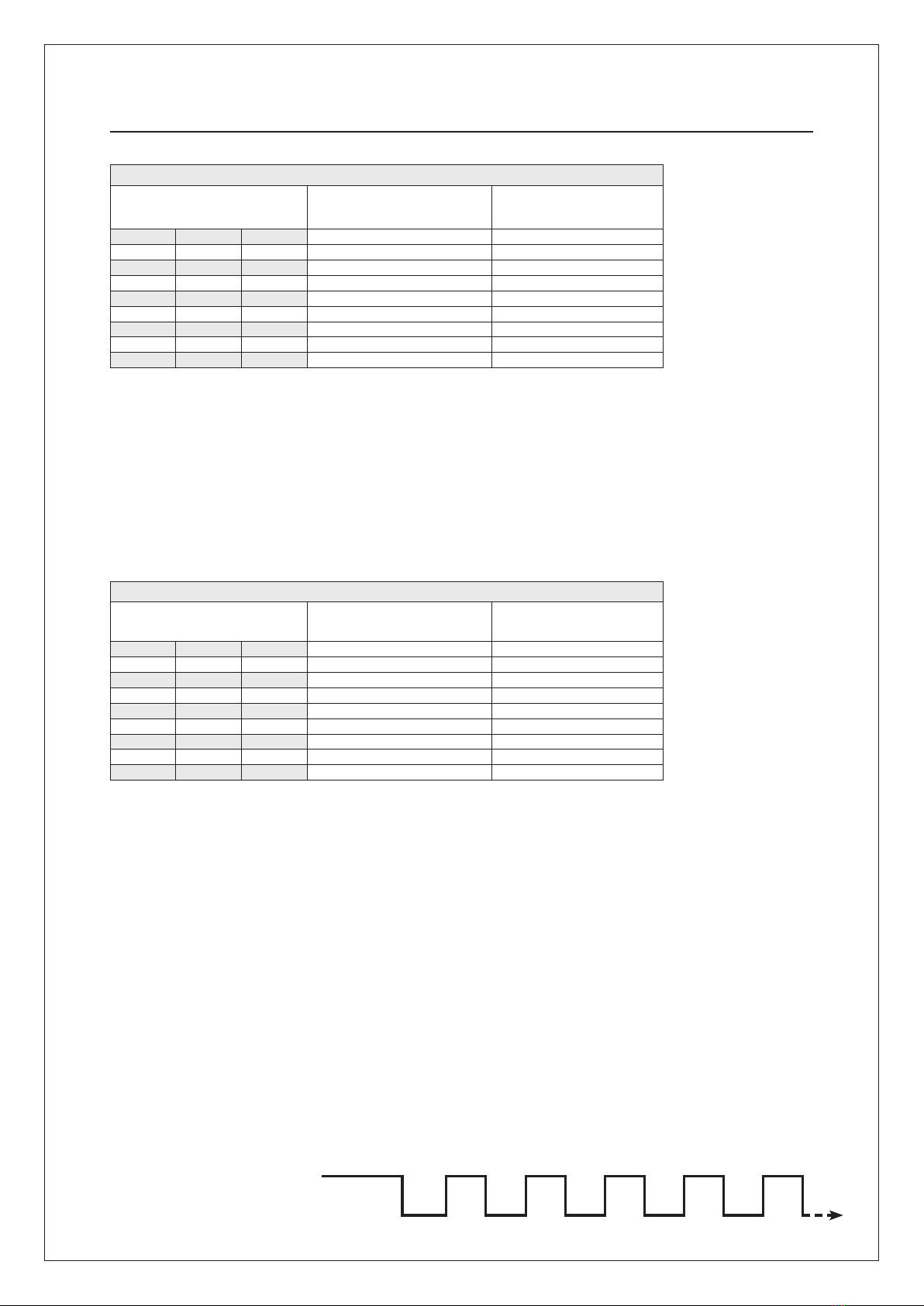
Break Break
PROTECT Pulse Effect
TM
60 sec. fog Fog output Fog output Fog outputFog outputFog output
BreakBreakBreak
PROTECT 2200iTM
GB:Totaltimeinpulsemode=6,5min.30sec.+pulseshots.Totalfog
production = 2500 m3.Totalcapacityintheuidcontainer=4complete
sequence in pulse mode.
F: Duréetotaleenmodepulse=6,5min.(30sec.+tirsenmodepulse).
Volume total de fumée = 2500 m3. Capacité totale d’une recharge de liquide:
4 séquences complètes en mode pulse.
I: Tempo massimo di erogazione in un ciclo con funzione ad impulsi = 6,5
minuti (30 sec. + erogazioni ad impulsi) Produzione totale nebbia = 2500
m3. Capacità massima di un contenitore di uido = 4 sequenze complete
(vedi sopra).
E: Tiempototalenmododepulsos=6,5min.30seg.+disparosdepulso.
Producción total de niebla = 2500 m3.Capacidadtotaldeldepósitodeuido
= 4 secuencias completas en modo de pulsos.
DK: Ialtca.6,5min.medpulsfunktion.30sek.+pulsskud.Totalproduktion
= 2500 m3tåge. Total kapacitet = 4 komplette sekvenser m/puls i en dunk.
PROTECT 2200iTM
GB: Total time in pulse mode = 11 min. 60 sec. + pulse shots. Total fog
production = 3700 m3. Total capacity in the uid container = 3 complete
sequence in pulse mode.
F: Duréetotaleenmodepulse=11min.(60sec.+tirsenmodepulse).Vol-
ume total de fumée = 3700 m3. Capacité totale d’une recharge de liquide: 3
séquences complètes en mode pulse.
I: Tempo massimo di erogazione in un ciclo con funzione ad impulsi = 11
minuti(1minuto+erogazioniadimpulsi).Produzionetotalenebbia=3700
m3. Capacità massima di un contenitore di uido = 3 sequenze complete
(vedi sopra).
E: Tiempototalenmododepulsos=11min.60seg.+disparosdepulso.
Producción total de niebla = 3700 m3.Capacidadtotaldeldepósitodeui-
do = 3 secuencias completas en modo de pulsos.
DK: Ialtca.11min.medpulsfunktion.60sek.+pulsskud.Totalproduktion=
3700 m3tåge. Total kapacitet = 3 komplette sekvenser m/puls i en dunk.
PROTECT 2200iTM
Dip Setting / Réglage DIP / Posizione DIP
DipConguración/Dipinstillinger
Fog Time / Durée de la fumée / Tempo di
erogazione nebbia / Tiempo de niebla /
Tågetid
Fog Volume / Volume de fumée /
Volume di nebbia prodotto
Volumen de niebla /
Tågevolumen
Dip 2 Dip 3 Dip 4
OFF OFF OFF demo demo
ON OFF OFF 20s 900
OFF ON OFF 40s 1800
ON ON OFF 60s 2700
OFF OFF ON 70s 2875
ON OFF ON 30s+6min.* 2500*
OFF ON ON 60s+10min.* 3700*
ON ON ON - -
PROTECT 1100iTM
Dip Setting / Réglage DIP / Posizione DIP
DipConguración/Dipinstillinger
Fog Time / Durée de la fumée / Tempo di
erogazione nebbia / Tiempo de niebla /
Tågetid
Fog Volume / Volume de fumée /
Volume di nebbia prodotto
Volumen de niebla /
Tågevolumen
Dip 2 Dip 3 Dip 4
OFF OFF OFF demo demo
ON OFF OFF 15s 500
OFF ON OFF 30s 875
ON ON OFF 45s 1200
OFF OFF ON 60s 1300
ON OFF ON 60s+4min.* 1700*
OFF ON ON - -
ON ON ON - -
PROTECT 1100iTM
GB: Total time in pulse mode = 5 min. 60 sec. + pulse shots.Total fog
production = 1700 m3.Totalcapacityintheuidcontainer=3complete
sequence in pulse mode.
F: Duréetotaleenmodepulse=5min.(60sec.+tirsenmodepulse).Vol-
ume total de fumée = 1700 m3. Capacité totale d’une recharge de liquide:
3 séquences complètes en mode pulse.
I: Tempo massimo di erogazione in un ciclo con funzione ad impulsi = 5
minuti(1minuto+erogazioniadimpulsi)Produzionetotalenebbia=1700
m3.Capacitàmassimadiuncontenitorediuido=3sequenzecomplete
(vedi sopra).
E:Tiempototalenmododepulsos=5min.60seg.+disparosdepulso.Pro-
ducción total de niebla = 1700 m3.Capacidadtotaldeldepósitodeuido=
3 secuencias completas en modo de pulsos.
DK:Ialtca.5min.medpulsfunktion.60sek.+pulsskud.Totalproduktion=
1700 m3tåge. Total kapacitet = 3 komplette sekvenser m/puls i en dunk.
GB: Pulse
F: Impulsion
I: Impulsivo
E: Pulsos
DK: Puls
*Not useable on 115/130 V markets. See supplement to this manual for low volt markets.
*Non applicable pour les Pays en 115/130 Volts. Voir le supplément à ce manuel pour les Pays à faible voltage.
*Non utilizzabile nei paesi con tenisone domestica di 115/130 V. Vedi nel supplemento manuale per basso voltaggio.
*Noutilizableenpaísescuyovoltajeseade115/130V.Veaelanexoaestemanualparalosmercadosconbajovoltaje
*Kan ikke bruges i lande med 115/130 V. Se tillæg til denne manual for lande med lav volt.

PROTECT 600i™, 1100i™, 2200i™15
Remember to heat the system before testing.
Ne pas oublier le temps de chauffe avant de tester.
Permettere al sistema di riscaldarsi prima di eseguire il test.
Recuerde el tiempo de calentamiento antes de realizar el ensayo.
Husk opvarmningstid før test.
Check the control signals before testing.
Contrôlerlessignauxdecommandeavantdetester.
Controllare i segnali di attivazione prima di iniziare Il test.
Controle las señales de mando antes de realizar el ensayo.
Kontroller styresignaler før afprøvning.
F
I
E
DK
GB 16
DK
Connectthebattery.Onebatterymeasures97x43x51mm.
Brancherlabatterie.Dimensiond’unebatterie:97x43x51mm.
Collegamento delle batterie.
Dimensionidiunabatteria:mm97x43x51.
Conexióndelabatería.Unabateríamide97x43x51mm.
Batteriettilsluttes.Etbatterimåler97x43x51mm.
F
I
E
GB 17
DK
Installtheuidcontainerandattachthemetalcover.
Installezlarechargedeuideetxezlecapotenmétal.
Installare il contenitore del liquido e chiudere il coperchio.
Fijeeldepósitodeuidoylatapametálica.
Installer væskedunken og sæt metalkabinettet på.
F
I
E
GB 18
PROTECT 600iTM
10-15
PROTECT 1100iTM
15-25
PROTECT 2200iTM
30-45
Min.
DK
F
I
E
GB 19
Full-scale test: Remember that the test must include the entire
alarm installation.
Test en situation réelle: Ne pas oublier d’inclure l’ensemble de
l’installation d’alarme dans l’essai.
Test completo: il test deve includere tutto l’impianto d’allarme.
Ensayo completo: Recuerde que el ensayo debe incluir toda la
instalación de alarma.
Fuld skala test: Husk: testen skal omfatte hele
alarminstallationen.
F
I
E
DK
GB 20

PROTECT 600i™, 1100i™, 2200i™
16
3. Hand over
F: Remise I: Consegna dell’impianto E: Entrega DK:Aevering
Checktheuidlevelaftertesting(handover
the Fog CannonTMwithafulluidcontainer).
Contrôler le niveau de liquide après l’essai (remettre le
générateur de fumée le réservoir rempli).
Controllare il livello di liquido nel contenitore dopo il
test. Consegnare al cliente il generatore di nebbia con
il contenitore pieno.
Controle el nivel del líquido después del ensayo
(entregue el generador de niebla con el recipiente de
líquido lleno).
Kontrollérvæskestandeneftertest(aevertåge-
kanonen med fuld væskedunk).
F
I
E
GB 21
Remember to put warning labels on the windows.
Ne pas oublier de bien placer les autocollants
d’avertissement sur les fenêtres.
Apporreleetichettediavvisosullesupercivetrate
(punti di accesso).
No olvide colocar las etiquetas de advertencia en las
ventanas.
Husk påsætning af advarselsmærkater på vinduerne.
F
I
E
GB 22
Before leaving the installation all users must be
instructed in how the Fog CannonTM works.
L’installationnie,l’installateurdoitinstruiretoututilisa-
teur dans le fonctionnement du générateur de fumée.
Al termine tutto il personale del locale deve essere
informato sul funzionamento del generatore nebbiogeno.
Antesdeabandonarlainstalación,asegúresedeque
todos los usuarios han sido instruidos en el manejo del
generador de niebla.
Før du forlader installationen, skal alle brugere
instrueres i hvorledes tågekanonen virker.
F
I
E
GB 23
DK
DK
DK
PROTECT 600i™, 1100i™, 2200i™17
The users must be informed that further information
can be found on www.protectglobal.com
Les utilisateurs doivent être informés de la possi-
bilité d’obtenir plus de renseignements sur le site
www.protectglobal.com
Informare il cliente che ulteriori informazioni
Sono disponibili sul sito www.protectglobal.com
Informe a los usuarios que pueden consultar
www.protectglobal.com para mayor información.
Brugerneskaloplyses,atereinformationerkan
ndespåwww.protectglobal.com
F
I
E
DK
DK
DK
GB 24
Complete the warranty sheet and send it to PROTECTTM.
Remplirlecerticatdegarantieetl’envoyeràPRO-
TECTTM.
La garanzia deve essere compilata ed inviata a PRO-
TECT
TM
.
La hoja de garantía debe rellenarse y enviarse
a PROTECTTM.
Garantibeviset udfyldes og sendes til PROTECTTM.
F
I
E
GB 25
Complete the sheet for the authorities and send it to
yourlocalpoliceandredepartment.
Remplirlanoticationauxautoritéspubliqueset
l’envoyeràlapoliceetaucorpsdespompierslocaux.
Compilare il modulo per le autorità locali ed inviarlo
agli organi di Polizia competenti e ai Vigili del Fuoco.
La hoja informativa para las autoridades debe
rellenarse y enviarse a la policía local y al departa-
mento de bomberos.
Meddelelse til myndigheder udfyldes og sendes til
det lokale politi og brandvæsen.
F
I
E
GB 26
WWW.PROTECTGLOBAL.COM
WWW.PROTECTGLOBAL.COM

PROTECT 600i™, 1100i™, 2200i™
18
GB: Service and maintenance agreement
A service agreement with the customer includes the follow-
ing:Visuallyinspect thefoguid level.Durability:5 years
from production date in unopened packaging. 2 years from
dateofinstallation.Donotusewhendiscolored!•Checkthe
loadingcapabilityandtheageofthebatteries•Ifthebatter-
iesaremorethan2yearsoldtheymustbereplaced•Check
if there is any fault indicated on the Fog CannonTM•Check
thatthe nozzleis cleanofforeignbodies• Checkifthere
areanysignsofsabotageandcheckthesabotageswitches•
Checkthattheverifyingsensorisworkingcorrectly•Makea
full-scale-test, where the interaction between all systems is
tested(alsotherealarmsystemifthere).
F: Recommandations de Service et de Maintenance
Contrat de service avec le client nal, celui-ci respectant
lespointssuivants:Vériervisuellementleniveaudeliquide
fumigène. Durée de vie: Sans á partir de ca date de fabrica-
tion si c’emballage n’est pas ouvert. 2 ans á partir de la date
d’installation.Nepasutiliserquandilestdécoloré•Vérier
leniveaudechargeetl’âgedesbatteries•Silesbatteries
ontplusdedeuxans,ellesdoiventêtreremplacées•Vérier
siil n’yapas dedéfaut (messaged’erreursur l’afcheur)
surl’appareil•Vérierquelabusenesoitpasobstruéepar
des “corps étrangers” • Vérier qu’il n’y ait pas de signe
demalveillancesurl’appareiletsurlesswitch•Vérierle
bonfonctionnement dudetecteur deconrmation•Tester
l’ensembledel’installationd’alarmeandeverierlesin-
terferencesdesdifférentsappareilsentreeux(ycomprisle
SSI si present).
I: Manutenzione
Un tipico contratto di manutenzione con il cliente contem-
pla: Ispezione visiva del livello di liquido nel contenitore.
Durata: Cinque anni dalla data di produzione con confezione
integra. Due anni dalla data di installazione. Non utilizzare
quandoscolorito! •Controllo dellostatodelle batterie:se
hanno più di due anni, devono essere sostituite • Verica
dieventualimessaggidierroresuldisplay•Controllodella
puliziadell’ugello•Vericaresesonopresentisegnidisabo-
taggioecontrollodelcontattoantisabotaggio•Controllodel
funzionamento corretto dell’ eventuale sensore di verica
collegato al generatore di nebbia • Controllo del corretto
funzionamento dell’intero sistema d’ allarme
E: Acuerdo de servicio y mantenimiento
Un acuerdo de mantenimiento con el cliente, que debe in-
cluirlosiguiente:Inspeccionevisualmenteelniveldeuido
de niebla. Durabilidad: 5 años a partir de la fecha de pro-
ducción para los productos sin abrir. 2 años a partir de la
fechadeinstalación.¡Noutilizarenelcasodeeluidohaya
perdidosucolor!•Compruebelacapacidadylaantigüedad
delasbaterías•Silasbateríastienenmásdedosañosdean-
tigüedad,debenserreemplazadas•Compruebesihayalgún
avisodeaveríaenelgeneradordeniebla•Compruebequela
boquillanoestáobstruidaporobjetosextraños•Compruebe
si hay alguna señal de sabotaje y compruebe los interrupto-
resdesabotaje•Compruebe queelsensor devericación
funcionacorrectamente•Hagaunapruebacompletadefun-
cionamiento, donde se compruebe la interacción de todos los
sistemas(inclusoelABAsiexiste).
DK:
Serviceaftale
En serviceaftale med kunden bør min. indeholde: Inspicer
tågevæskestand visuelt. Holdbarhed: 5 år fra produktions-
dato i uåbnet emballage. 2 år fra installationsdato (ved mis-
farvningkasseresvæsken)•Undersøgbatteriernesbelastba-
rhedogalder•Erbatterierne2årellermere,børdeunder
alleomstændighederskiftes•Erdereventueltfejlmeldinger
påmaskinen?•Erudblæsningsdysenfriforfremmedlegemer?
•Erdertegnpåsabotage?Kontrollersabotageswitse•Virker
denvericerendesensor,somdenskal?•Foretagenfuld-ska-
la-test, hvor samspillet mellem alle systemer afprøves (også
ABA hvis til stede).
Finally, a contract of service must be made, which
should contain an agreement for min. one test a year.
Finalement, dresser un contrat d’entretien qui doit
comprendre au minimum un essai par an.
Sisuggerisceinnedistipulareconilcliente
un contratto di manutenzione.
Porúltimo,debermarseuncontratodeservicioqueincluyaun
acuerdo de 1 prueba anual como mínimo.
Afslutningsvis indgås serviceaftale, som bør
indeholde en aftale om min. 1 årlig test.
F
DK
I
E
GB 27

PROTECT 600i™, 1100i™, 2200i™19
4. In case of faults
F: En cas de défauts In caso di funzionamento anomalo En caso de averías I tilfælde af fejl
GB F I E DK
1Identify the error
(see code on the display)
Identierl’erreur
(voir le code sur l’écran)
Identicailtipodierrore
(vedi il codice sul display)
Identiqueelfallo
(véase el código en el display)
Identicérfejlen
(Se koden i displayet)
2Find the cause of the error Trouver la cause de l’erreur Individua la causa dell’errore Determine la causa del fallo Find årsagen til fejlen
3Correct the cause of the error Corriger la cause de l’erreur Elimina la causa dell’ errore Corrija la causa del fallo Ret fejlen
GB:FaultndingF: Défauts possible I: Uscite di allarme E: Salidas de avería DK:
Fejlnding
GB F I E DK
Fluid Outputactivatedifuidlevelis
too low.
La sortie est activée si le niveau
de liquide est bas.
L’uscita si attiva quando il livello
di liquido è troppo basso.
La salida se activa si el nivel de
líquido es demasiado bajo.
Udgang trækker, hvis væske-
standen bliver lav.
Fault Output activated in case of system
error. Error type can be read in
the display.
La sortie est activée lors d’une
erreur de l’appareil. Le type
d’erreur est indiqué sur l’écran.
L’uscita si attiva in caso di anoma-
lia di sistema. Il tipo di guasto
viene indicato sul display.
La salida se activa en caso de un
fallo en el aparato. El tipo de fallo
se lee en el display.
Udgang bliver aktiv ved en
fejl i apparatet. Fejltypen kan
aæsesafdisplayet.
Fog When the Fog CannonTM produces
fog, this output will activate.
Lorsque le générateur produit de
la fumée, cette sortie est activée.
L’uscita è attiva durante la gener-
azione di nebbia.
Cuando el generador produce
niebla, esta salida se activa.
Når tågekanonen producerer
tåge, vil denne udgang blive
aktiv.
GB:
Fuses
F:
Fusibles
I:
Fusibili
E:
Fusibles
DK:
Sikringer
230V AC Fuses / Fusibles / Fusibili / Fusibles / Fuses PROTECT 600iTM PROTECT 1100iTM PROTECT 2200iTM
F1 (Incoming Power/High Voltage) 10 AT 10 AT 10 AT
F3 6.3 AT 8 AT 10 AT
F4 0.5 AT 0.5 AT 1 AT
GB: AnidentiederrorcanberesetbypressingtheResetbuttonforapprox.4seconds.Thebuttonislocatedinthecentreofthecircuitboard.
F: Une faute enregistrée est remise à zéro en appuyant pendant environ 4 secondes sur la touche “Reset” qui est située au milieu de la carte électronique.
I: Un errore segnalato sul display può essere cancellato premendo il pulsante reset per circa 4 secondi. Il pulsante si trova al centro della scheda elettronica.
E: Parareiniciarunfalloregistrado,mantengapulsadoelbotón“Reset”,queestásituadoenelcentrodelaplacaelectrónica,aprox.4segundos.
DK: En registreret fejl nulstilles ved at trykke på “Reset” knappen, placeret midt på elektronikkortet i ca. 4 sekunder.
PROTECT 600i™, 1100i™, 2200i™
20
Green and yellow light / Lumière verte et jaune /
Luce verde e giallo / LED Luz verde y amarilla /
Grøn og gult lys
Red light / LED rouge / Led rosso / Luz roja / Rødt lys
GB
GreenLEDashesrsttimetheFogCannonTM is connected to mains power.
Green LED lights constantly on when the Fog CannonTM is heated and ready.
YellowLEDashesforlowuidlevel.Checkuid.AllLEDsareturnedoff
when Fog CannonTM has arm signal from alarm panel (disable signal is re-
moved).
OneRedashevery10seconds(E1):Mainspowerfailure(andnocriticalfailure
atthesame time).ThreeRedashesevery10seconds (E3):Firealarm input
activated(andnocriticalfailureatthesametime).FourRedashesevery10
seconds (E4): Low battery voltage (and no critical failure at the same time).
Alarminstalleris required!ConstantRedashing:Seriousfailure(s) detected.
Alarm installer is required!
F
Led verte clignote à la première connection électrique du canon à fumée.
Led verte est allumée en permanence lorsque le canon à fumée est chaud
et est prêt à fonctionner. Led jaune clignote lorsque le niveau du liquide
estbas.Vériezleproduit.Touslesvoyantssontéteintslorsquelecanon
à fumée est mis en Marche à partir du clavier d’Alarme ( le contact « DIS-
ABLE »est enlevé: 0V).
Unashrougetoutesles10secondes(E1):défautsecteur(220V).Troisclignote-
ments rouges toutes les 10 secondes (E3): activation de l’entrée FIRE. Quatre
clignotements rouges toutes les 10 secondes (E4): batterie basse. Clignotement
rouge constant: panne majeure: nécessite une intervention de l’installateur.
I
Led verde lampeggia al collegamento alla alimentazione di rete. Led verde
costantementeacceso:sistemapronto.Ledgiallolampeggia:uidobasso,
controllareillivellodeluido.TuttiiLedsspenti:ilnebbiogenoèsettato
in ARM dal sistema d’allarme (comando DISABLE assente).
1 Flash del Led rosso ogni 10 secondi (E1): mancanza di alimentazione di rete
(senza contemporaneamente allarme critico). 3 Flashes del Led rosso ogni 10
secondi (E3): ingresso allarme incendio attivato (senza contemporaneamente
allarme critico). 4 Flashes del Led rosso ogni 10 secondi (E4): voltaggio basso
delle batterie (senza contemporaneamente allarme critico). Necessario inter-
vento tecnico.
Led rosso lampeggio costante: guasto grave, necessario intervento tecnico.
E
El Led verde parpadea al conectar por primera vez el Generador de Nie-
bla a la corriente alterna. El Led verde se mantiene encendido cuando el
Generador de Niebla está caliente y preparado. El Led amarillo parpadea si
haybajoniveldeuido.Veriquedichonivel.TodoslosLedsseapagarán
al activar el Generador de Niebla desde el sistema de alarma (se retira la
señal de inhabilitación).
Un parpadeo rojo cada 10 segundos (E1): Fallo de alimentación de red (y sin
fallo crítico al mismo tiempo). Tres parpadeos en rojo cada 10 segundos (E3):
Activación de la entrada de alarma de incendio (y sin fallo crítico al mismo
tiempo). Cuatro parpadeos en rojo cada 10 segundos (E4): Baja batería (y sin
fallo crítico al mismo tiempo). Se requiere la presencia del instalador. Parpadeo
constante en rojo: Se ha producido una avería importante. Se requiere la pres-
encia del instalador.
DK
Grøn diode blinker, når der sættes strøm til tågekanonen. Grøn diode ly-
ser konstant, når tågekanonen er varm og klar. Gul diode blinker ved lav
væskestand. Kontroller væske. Alle lysdioder slukkes, når alarmen tilko-
bles. (disable-signalet fjernes).
Ét blink pr. 10 sek. (E1): Ved svigt af netspænding (og der samtidig ikke er en
mere kritisk fejl). Tre blink pr. 10 sek. (E3): Ved aktiveret brandalarmindgang (og
der samtidig ikke er en mere kritisk fejl). Fire blink pr. 10 sek. (E4): Ved lav bat-
terispænding (og der samtidig ikke er en mere kritisk fejl). Kræver servicebesøg.
Konstant blinken: Ved alvorlige fejl, som kræver indgreb fra installatøren.
GB: ExternalLEDstatusindicator–aservicefunctioninarmand
disarm status.
F: LEDexterieured’indicateursd’état–
fonctionmiseen-ouhors-servicedusystème(+/-12vsurDIS).
I: Indicatore esterno di stato a LEDs,
diagnostiche di guasto.
E: IndicadorLEDexternodeestado-
encendido tanto en estado de armado como desarmado.
DK: Dioder til ekstern statusmelding - en servicefunktion i frakoblet
og tilkoblet tilstand.
Other manuals for 600i Series
3
This manual suits for next models
2
Other Protect Fog Machine manuals


