Protecta EuroProt+ Series User manual

Quick start guide
to the devices of the EuroProt+
product line
Document ID: VERSION 1.0
Budapest, November 2010.

Quick start guide to the devices of the EuroProt+ product line
VERSION 1.0 2/14
User’s manual version information
Version
Date
Modification
Compiled by
Preliminary
24.11.2009.
Preliminary version
Petri
Version 1.0
11.11.2010.
First edition
Petri

Quick start guide to the devices of the EuroProt+ product line
VERSION 1.0 3/14
CONTENTS
1Application...........................................................................................................................4
2Meeting the device ..............................................................................................................4
2.1 Power supply................................................................................................................4
2.1.1 The power supply module.....................................................................................4
2.1.2 The hardware modules of the device....................................................................5
2.1.3 Fast startup...........................................................................................................5
2.2 The front panel of the device........................................................................................6
2.2.1 The structure of the human-machine interface of the device ...............................6
2.2.2 Using the menu provided by the touch-screen.....................................................7
2.3 Using the embedded WEB server................................................................................9
2.3.1 Properties of the Ethernet communication............................................................9
2.3.2 The Ethernet connection.................................................................................... 10
2.3.3 Settings needed for Ethernet connection........................................................... 14
2.3.4 Using WEB browsers......................................................................................... 14

Quick start guide to the devices of the EuroProt+ product line
VERSION 1.0 4/14
1 Application
The EuroProt+ type complex protection in respect of hardware and software is a modular
device. The modules are assembled and configured according to the requirements, and then
the software determines the functions. This manual describes the common properties of the
numerous possibilities. The individual characteristics of the specific applications are described
in the manuals of the factory configurations.
2 Meeting the device
In order to meet the device at the first time, this chapter describes information, which might be
necessary for new users to get familiar with the basic properties of the device.
2.1 Power supply
2.1.1 The power supply module
Power supply module converts primary AC or DC primary voltage to required system
voltages. In most cases of applications one power supply card is enough to provide the
required power to the system. Redundant power supply cards extend system availability in
case of outage of any power source.
Main features of the standard power supply modules are:
30W and 60W power versions (PS+1030, PS+1060)
80V-300VDC input range, AC power also supported
Power connector (1-2):
oReceptacle: Weidmüller SLA90/2
oPlug: Weidmüller BLA2
The power supply module contains contacts for error signaling:
Fault relay contacts (NC and NO): device fault contact and also assignable to
user functions. All the three relay contact points are (NO, NC, COM)
accessible to users
Fault relay connector (3-4-5):
oReceptacle: Weidmüller SLA90/3
oPlug: Weidmüller BLA3
(For devices produced for special requirements please see technical details in the
configuration manual of the devices.)
The standard power supply modules (rear view) are shown in Figure 2-1.

Quick start guide to the devices of the EuroProt+ product line
VERSION 1.0 5/14
Figure 2-1 The standard power supply modules
2.1.2 The hardware modules of the device
For technical details of the modules of the EuroProt+ type complex protection please see the
document “Hardware description”. The applied modules are listed in the document
“Configuration description”.
2.1.3 Fast startup
The CPU module of the device is equipped with two powerful processors: one for performing
the application functions (RDSP), the other one for processing the communication tasks
(CDSP).
After power-up the RDSP processor starts-up with the previously saved configuration and
parameters. Generally the power-up procedure for the RDSP and application functions takes
approx. 4-5 sec. During this period of time the “Device LED” (see Figure 2-2) is yellow. If the
protection functions are ready for operation the yellow LED turns to green, the protection
functions are ready to trip after this short period. (During the restart procedure after a new
downloaded configuration the LED is red for a short time. Latched red LED however means
general error. In this case the protection functions are not available.)
The CDSP’s start-up procedure is longer, because its operating system needs time to build its
file system, initializing user applications such as HMI functions and IEC61850 software stack.
The availability of the touch-screen of the front panel after about 25-30 seconds indicates
successful termination of the start-up procedure.

Quick start guide to the devices of the EuroProt+ product line
VERSION 1.0 6/14
2.2 The front panel of the device
Figure 2-2 The front panel of the device
2.2.1 The structure of the human-machine interface of the device
The EuroProt+ device HMI of the front panel contains the following elements:
Function
Description
16pcs user LEDs
Three-colors, 3mm circular LEDs
COM LED
Yellow, 3mm circular LED indicating EOB communication link
and activity
Touch key LEDs
4pcs yellow, 3mm circular LEDs indicating touch key actions
Device LED
1pc three-colors, 3mm circular LEDs
Green: normal device operation
Yellow: device is in warning state
Red: device is in alarm state
Touch keys
Four capacitive touch keys (On, Off, Page, LED
acknowledgement)
Buzzer
Audible touch key pressure feedback
Changeable LED
description label
Describes user LED functionality
3.5” or optional 5.7” display
320*240 pixels TFT display with resistive touch screen interface
Optical interface for factory
usage
EOB connector
Ethernet Over Board: communication interface accomplishes
isolated, non-galvanic Ethernet connection with the help of a
magnetic attached EOB device. The EOB device has an RJ45
type connector supporting 10Base-T Ethernet connection to the
user computer. This is a proprietary and patented solution from
Protecta ltd.
Table 2-1 The elements of the front panel
COM LED
Change
screen
button
3.5” TFT display
Changeable
LED description
label
User LEDs
Optical
interface
for factory
usage
Touch key LEDs
Device LED
EOB
connector
LED
Reset key
Operation
buttons

Quick start guide to the devices of the EuroProt+ product line
VERSION 1.0 7/14
2.2.2 Using the menu provided by the touch-screen
The main screen of the local LCD together with the “Change screen button” and the
“Operation buttons” are shown in Figure 2-3.
Figure 2-3 The main screen
Touchscreen - The main control area where the user will enable functions and input values
by touching the screen.
Change screen button - This hardware button changes the currently displayed screen for
the subsequent one. The available screens and the order in which they appear by default are:
the main screen, parameters, on-line, events, system settings and the custom screens which
can be added by the user with the help of the EUROCAP software.
Operation buttons - These buttons can be used to define certain functions on customer-
defined windows. For example, the user can set up these buttons to turn on / off a circuit
breaker or increment/decrement the position of the tap charger of a transformer. For more
information, please refer to the User-defined / custom screen section.
Lock icon –The factory setting of the device excludes the password protection function.
When touching this icon the picture changes, enabling all kind of operation. If this kind of
limitation by password protection at operation is needed then the password application can be
set via WEB interface. In this case the icon is changing only if the correct password is
entered.
When pressing the “Change screen button” –as an example - the windows shown in
Figure 2-4 can be seen and applied one-by-one, cyclically.

Quick start guide to the devices of the EuroProt+ product line
VERSION 1.0 8/14
Figure 2-4 Some screens displayed on the LCD
Touch the navigation icons or the displayed text lines to perform any actions via the LCD
screen. For further details see the document “LCD touch-screen interface description”.

Quick start guide to the devices of the EuroProt+ product line
VERSION 1.0 9/14
2.3 Using the embedded WEB server
2.3.1 Properties of the Ethernet communication
The built-in 5 port Ethernet switch allows EuroProt+ to be connected to IP/Ethernet based
networks. The following Ethernet ports are available:
On the front panel of the device:
EOB (Ethernet over Board) 10 Base-Tx user interface
On the rear side of the CPU unit (See Figure 2-5 and Table 2-2):
Station Bus (100Base-FX Ethernet)
Redundant Station Bus (100Base-FX Ethernet)
Process bus (100Base-FX Ethernet in preparation)
Optional 10/100Base-Tx port via RJ-45 connector
CPU version
Station bus
Redundant
Station bus
EOB
RJ-45
Process
bus
Legacy
port/protocol
CPU+0001
Yes
No
Yes
Yes
Prep
No
CPU+0002
Yes
Yes
Yes
No
Prep
No
CPU+0003
Yes
Yes
Yes
No
No
No
Table 2-2 The versions of the Ethernet communication
Figure 2-5 The versions of the CPU units

Quick start guide to the devices of the EuroProt+ product line
VERSION 1.0 10/14
Interface types:
On the front panel of the device:
EOB interface: attachable to the front panel by a proprietary magnetic connector, the
connector box ends in RJ45 8/8 plug. It is 10Base-T Full duplex interface.
On the rear side of the CPU unit (See Figure 2-5 and Table 2-2):
100Base-FX Ethernet: ST type, 1300nm/MM, for 50 m/125 m or 62.5 m/125 m
fiber
10/100 Base-TX Ethernet: RJ45-8/8
The embedded WEB-server supports the following actions:
Modifying user parameters
Checking events list and disturbance records
Managing the Password
Online displaying measured data and generated binary information
Performing commands
Providing remote or local firmware upgrade possibility
Performing administrative tasks
2.3.2 The Ethernet connection
There are several ways to be connected to an Ethernet network.
2.3.2.1 Using the EOB connection
Attach the magnetic EOB connector to the front panel of the device. The magnets assure the
correct position of the adapter. Connect the other end of the cable to the RJ-45 socket of a
computer: Figure 2-6. (The RJ-45 connector of the cable can also be connected to an
Ethernet switch. In this connection all IED-s on the network with client functionalities, e.g. a
computer, has access to the device.)
Figure 2-6 Using the EOB connection

Quick start guide to the devices of the EuroProt+ product line
VERSION 1.0 11/14
2.3.2.2 Using the RJ-45 connection
The CPU version 0001 (see above) also has an RJ-45 socket. Using a UTP cross-cable with
RJ-45 connector at both ends, the device can be connected directly to a computer: Figure
2-7. (The RJ-45 connector of the cable can also be connected to an Ethernet switch. In this
connection all IED-s on the network with client functionalities, e.g. a computer, has access to
the device: Figure 2-8.) (For information purposes the UTP cross-cable is explained in
Figure 2-10. )
Figure 2-7 Using the RJ-45 connection to connect a computer directly
Figure 2-8 Using the RJ-45 connection to connect computers via Ethernet switch
Quick start guide to the devices of the EuroProt+ product line
VERSION 1.0 12/14
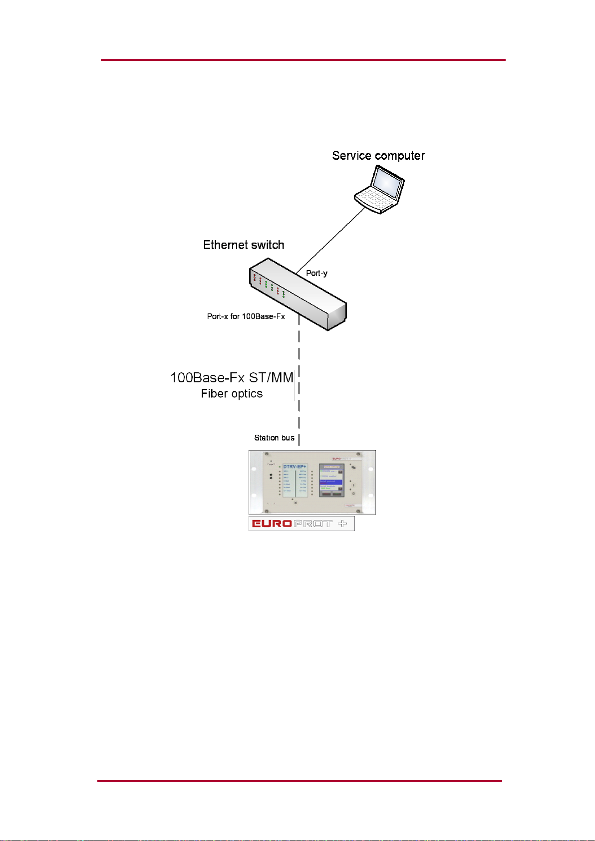
2.3.2.3 Using the ST type fiber optic connection
The ST type fiber optic connector of the 100Base-FX Ethernet provides connection to an
Ethernet switch with identical fiber optic input. Using this connection all IED-s on the network
with client functionalities, e.g. a computer, has access to the device: Figure 2-9.
Figure 2-9 Using the ST type fiber optic connection to connect computers via optical
Ethernet switch

Quick start guide to the devices of the EuroProt+ product line
VERSION 1.0 13/14
Cross-cable pinout
Figure 2-10 Pinout of the cross-cable

Quick start guide to the devices of the EuroProt+ product line
VERSION 1.0 14/14
2.3.3 Settings needed for Ethernet connection
The EuroProt+ devices can be accessed over Ethernet based protocols only. That's why it is
extremely important to set up the network before accessing the device.
IP settings:
The device operates with fixed IPv4 addressing. Dynamically assigned IP addresses are at
present not supported. It is suggested to use the private address range as defined in
RFC1918.
To connect to a standalone device just plug the EOB cable into your computer or use the RJ-
45 connector on the back panel of the device. (In this case you need a crossover UTP cable).
The computer should be set to use fixed IP settings. The addresses must be in the same
network range.
To connect the device to a station or corporate network, contact the system administrator for
available IP address, gateway address, net-mask, DNS and NTP server addresses.
WEB browser settings:
Please make sure your browser does not use proxy server while accessing the EuroProt+
device.
Contact your system administrator to add an exception if there is a proxy server on your
network.
2.3.4 Using WEB browsers
A compatible web browser and an Ethernet connection is needed in order to access the
device interface. To properly display the data on the screen, it is recommended that the user
have a screen resolution of at least 1024x768. The following web browsers can be used:
Microsoft Internet Explorer 7.0 or higher version.
Mozilla Firefox 1.5 or higher version.
Apple Safari 2.0.4 or higher version
Google Chrome 1.0 or higher version
Opera 9.25 or higher version
Javascript must also be enabled within your browser.
Type the IP address of the device into your browser’s address bar. (The IP address can be
read on the main screen of the local LCD, see Figure 2-3.) Follow the usual procedures of
WEB browsing.
Please see the details in the document “Remote user interface description”.
Table of contents
Other Protecta Protection Device manuals


