Satel INT-KWRL User manual

int-kwrl_en 05/18
Wireless keypad
INT-KWRL
Firmware version 2.15
SATEL sp. z o.o. • ul. Budowlanych 66 • 80-298 Gdańsk • POLAND
tel. +48 58 320 94 00
www.satel.eu

WARNINGS
The device should be installed by qualified personnel.
Read carefully this manual before proceeding to installation.
Changes, modifications or repairs not authorized by the manufacturer shall void your rights
under the warranty.
The name plate of the device is located on the enclosure base.
SATEL's goal is to continually upgrade the quality of its products, which may result in some
changes of their technical specifications and firmware. The current information on
the introduced modifications is available on our website.
Please visit us:
http://www.satel.eu
Hereby, SATEL sp. z o.o., declares that this keypad is in compliance with the essential
requirements and other relevant provisions of Directive 2014/53/EU. The declaration of
conformity may be consulted at www.satel.eu/ce
The following symbols may be used in this manual:
- note;
- caution.

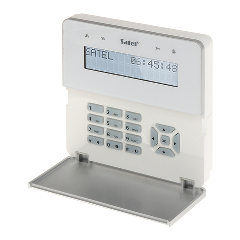
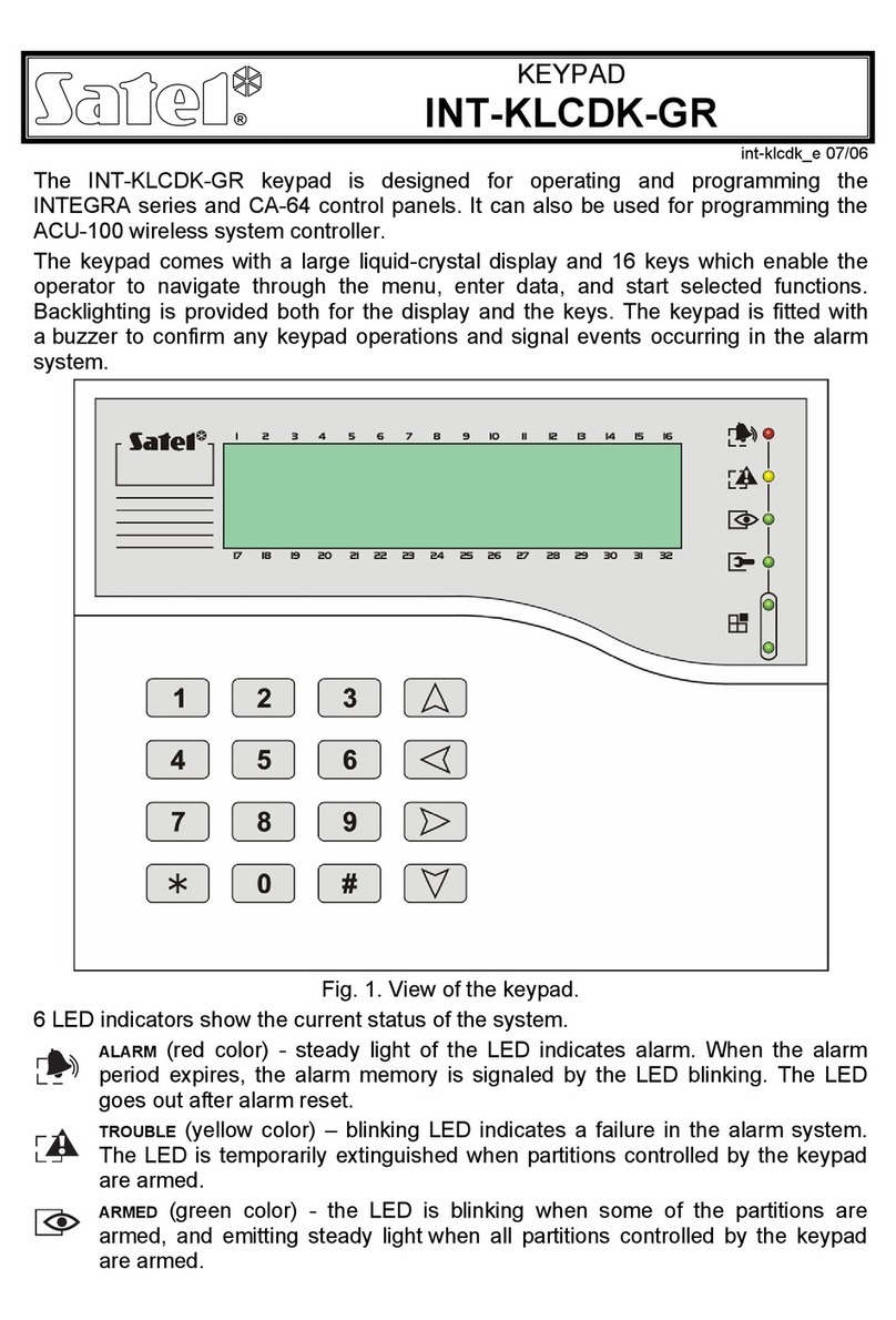
The INT-KWRL wireless keypad enables operation and programming of the INTEGRA and
INTEGRA Plus control panels with firmware version 1.17 (or newer). The device is designed
for work within the ABAX two-way wireless system. It is supported by the ACU-120 /
ACU-270 controller with firmware version 5.03 (or newer) connected to the INTEGRA /
INTEGRA Plus control panel.
The ACU-120 / ACU-270 controller which is to support the INT-KWRL keypad must be
connected to the expander bus (controller terminals CKE and DTE) and the keypad
bus (controller terminals CKM and DTM) of the alarm control panel.
Switch 8 in the ACU-120 / ACU-270 controller must be set to the OFF position.
The keypad is not supported by the ARU-100 radio signal repeater or by the
INTEGRA 128-WRL control panel.
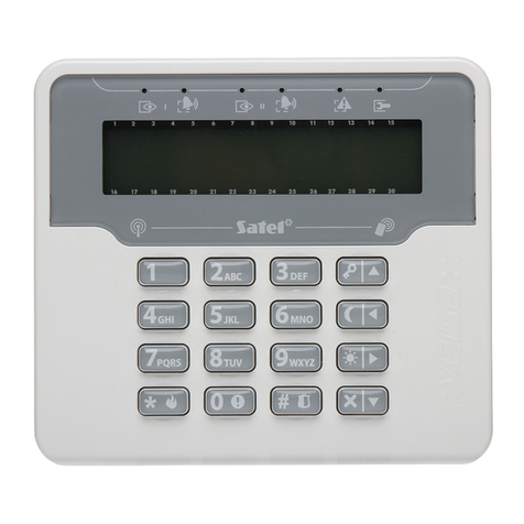
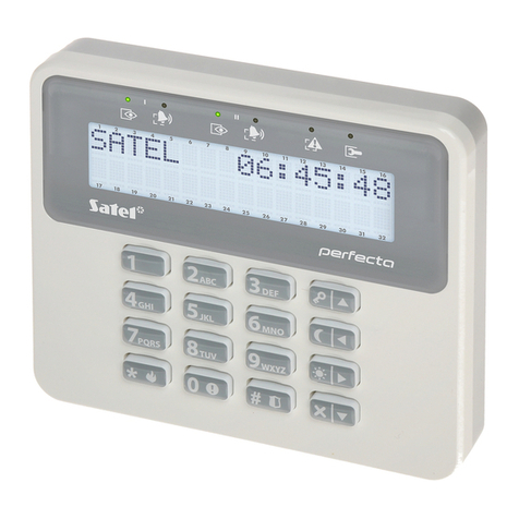
Fig. 1. INT-KWRL keypad.

2 INT-KWRL SATEL
1. Features
Two-way encrypted radio communication in the 868 MHz frequency band.
Display 2 x 16 characters with backlight.
LEDs indicating the state of system.
12 keys, bearing designations according to telephone standard and intended for entering
data.
4 additional keys for menu navigation.
An extra key to confirm the data entered.
Backlit keys.
Built-in proximity card reader.
Built-in sounder.
Tamper contact reacting to the enclosure opening or detaching from the wall.
Power supply: two CR123A 3 V batteries.
2. Description
Operating modes
The keypad can work in two modes:
active mode – started by pressing any key. Additionally, the active mode can be started
automatically when an alarm occurs or an entry delay, an exit delay or an auto-arming
delay begins (see description of the W
AKE
-
UP
parameter, section “Settings stored in ABAX
system controller” p. 6). In the active mode, the keypad operation is similar to that of the
wired LCD keypad. The display is on. Backlight, LED indication and sound signaling are
enabled.
inactive mode – is entered:
– after 20 seconds since the last key press,
– after preset time, if the active mode was started automatically (see description of the
W
AKE
-
UP
parameter, section “Settings stored in ABAX system controller” p. 6).
The purpose of the inactive mode is to save energy. The display is off. Backlight, LED
indication and sound signaling are disabled (if a time different from 0 is preset for the
W
AKE
-
UP
parameter, CHIME from zones will be signaled).
Support for proximity cards
The built-in proximity card reader enables the system to be operated by using proximity cards
(any 125 kHz passive transponder in the form of a card, tag, etc.). Where the alarm system is
not to be operated by proximity cards, the reader can be disabled (to prolong the battery life).
Periodic transmissions
Every 15 minutes, the keypad sends a periodic transmission. The purpose of such
transmissions is to monitor presence and condition of the keypad.
Battery status control
The keypad controls the status of the batteries. If the voltage is lower than 2.6 V:
low battery information is sent during each periodic transmission,
on starting the active mode, a low battery message will be displayed (the message will
specify which battery is to be replaced – see also Fig. 3).
SATEL INT-KWRL 3
The battery life depends on how the keypad is used. The more frequently the active
mode is entered, the quicker the batteries will be depleted.
3. Installation
There is a danger of battery explosion when using a different battery than
recommended by the manufacturer, or handling the battery improperly.
Be particularly careful during installation and replacement of the batteries. The
manufacturer is not liable for the consequences of incorrect installation of the
battery.
The used batteries must not be discarded, but should be disposed of in
accordance with the existing rules for environment protection.
The keypad is designed for indoor installation. The place of installation should be readily
accessible to the system users. When selecting the installation location, take into account the
communication range of the ABAX system.
1. Open the keypad enclosure (Fig. 2). The enclosure opening tool, shown in the illustration,
is included in the keypad delivery set.
Fig. 2. Opening the enclosure.
2. Install the batteries and add the keypad to the wireless system (see “Adding the keypad to
the wireless system”).

4 INT-KWRL SATEL
Fig. 3. Keypad enclosure inside with batteries installed.
3. Put the cover on the catches and snap the enclosure shut.
4. Place the keypad in the location intended for its installation.
If you want to hold the keypad in your hand when checking the radio signal level, grab
the device from its left side (on its right side, there is the antenna, which must not be
covered).
5. Check the level of signal received from the keypad by the ACU-120 / ACU-270 controller.
If the signal level is lower than 40%, select another place for installation. Sometimes, it is
sufficient to shift the device ten or twenty centimeters to obtain a considerable
improvement in the signal quality. Only after the optimal level of radio signal is achieved
can you proceed to the next step.
6. Open the keypad enclosure (Fig. 2).
7. Place the enclosure base against the wall and mark location of the mounting holes.
8. Drill the holes in the wall for wall plugs (screw anchors).
9. Using wall plugs (screw anchors) and screws, secure the enclosure base to the wall.
Select wall plugs and screws specifically intended for the mounting surface (different for
concrete or brick wall, different for plaster wall, etc.). When installed, the device must
withstand a pull-off force of at least 50 N.
10.Put the cover on the catches and snap the enclosure shut.
11.Lock the cover using screw.
3.1 Adding the keypad to the wireless system
Before adding a keypad, make sure that the controller terminals CKM and DTM
are connected with the keypad bus of the control panel, and the switch 8 in the
controller is set to the OFF position.
You can add the wireless keypad to the ABAX system by using either a computer with
DLOADX program installed, or an LCD keypad. The controller allows for registering of up to 4
INT-KWRL keypads. If no wired keypad is connected to the control panel, you can only add
the first wireless keypad using the DLOADX program (to establish communication between

SATEL INT-KWRL 5
the program and the control panel, you must start the service mode “from pins” – refer to the
control panel programming manual).
3.1.1 DLOADX program
You can add wireless keypad in the “Structure” window, “Hardware” tab, after clicking on the
name of ABAX system controller on the list of devices, and then on the “INT-KWRL” tab (see
Fig. 4p. 7).
1. Click on the “Read” button to read the data related to wireless keypads from the controller
(these data are not read after clicking on the button in the main menu).
2. Click on the “New device” button.
3. The “New device” window will open.
4. In the “Serial number” field enter the serial number of the added keypad. The sticker with
serial number you will find on the electronics board.
5. In the “Address” field, select which address is to be assigned to the keypad to be added.
6. Press any key on the keypad
7. The message will confirm that a keypad has been added (unless you have entered an
invalid serial number, of which you will be informed by a message). The name assigned to
the keypad will be displayed. You can change it.
8. Click “OK” (to cancel adding the keypad, click on the “Quit” button).
9. The “New device” window will close.
10.The new keypad will appear in the table in “INT-KWRL” tab.
11.Click on the “Keypads identification” button (the new keypad must be identified by the
control panel).
3.1.2 LCD keypad
You can add wireless keypad in the service mode by means of the N
EW DEVICE
function
(S
TRUCTURE
HARDWARE
E
XPANDERS
SETTINGS
[controller name] N
EW DEVICE
).
1. Having started the function, enter the serial number of the added keypad. The sticker with
serial number you will find on the electronics board.
2. Press .
3. When the “Open device tamper” message is displayed, press any key on the keypad.
4. Information on the added keypad will be displayed (if nothing happens, it can mean that
you have entered an invalid serial number – if this is the case, press to return to
the submenu).
5. Press .
6. Use the and keys to select address for the keypad being added.
7. Press .
8. Identification function will start automatically (the new keypad must be identified by the
control panel).
3.2 Removing the keypad from the wireless system
3.2.1 DLOADX program
You can remove the wireless keypads in the “Structure” window, “Hardware” tab, after
clicking on the name of ABAX system controller on the list of devices, and then on the “INT-
KWRL” tab (see Fig. 4p. 7).

6 INT-KWRL SATEL
1. Click on the “Read” button to read the data related to wireless keypads from the
controller.
2. Click on the wireless keypad you want to remove.
3. Click on the “Remove device”
button.
4. The “Confirm” window will open.
5. Click on the “Yes” button.
6. The “Confirm” window will close.
3.2.2 LCD keypad
You can remove wireless keypads in the service mode by means of the R
EMOVE DEVICE
function (S
TRUCTURE
HARDWARE
E
XPANDERS
SETTINGS
[controller name] R
EMOVE
DEVICE
).
1. Having started the function, use the and keys to select the keypad you want to
remove.
2. Press .
3. A prompt will be displayed asking you whether to remove the keypad and the serial
number of the keypad being removed.
4. Press .
4. Configuring
You can configure the wireless keypad settings by using a computer with DLOADX program
installed, or an LCD keypad.
4.1 Settings stored in ABAX system controller
These settings you can configure:
DLOADX program: “Structure” window “Hardware” tab “Expansion modules” branch
[controller name] “INT-KWRL” tab (see Fig. 4),
LCD keypad: S
ERVICE MODE
S
TRUCTURE
H
ARDWARE
E
XPANDERS
S
ETTINGS
[controller name] S
ETTINGS
[wireless keypad name].
4.1.1 Description of parameters and options
Given in the square brackets are the names of parameters and options presented on the
keypad display.
Wake-up [Wake up] – maximum length of time for which the active mode can be started
automatically. If you enter a value different from 0:
– the active mode will be started automatically when an alarm occurs or an entry delay,
an exit delay or an auto-arming delay begins,
– the CHIME from zones will also be signaled in the inactive mode.
If you enter 0, the active mode will not be started automatically.
If a value different from 0 is preset for the W
AKE
-
UP
parameter, the keypad will be
awaiting for transmissions with information on events. As a result, the energy
consumption will be growing and the battery life will be considerably reduced.
Card reader [Reader] – if this option is enabled, the card reader is supported.
Presence contr. [Test] – if this option is enabled, the keypad presence is being monitored. If
there is no transmission from the keypad for 1 hour, missing keypad will be reported.

SATEL INT-KWRL 7
Fig. 4. DLOADX
program: keypad settings stored in the ABAX system controller.
4.2 Settings stored in the control panel
These settings you can configure:
DLOADX program: “Structure” window “Hardware” tab “Expansion modules” branch
[keypad name] (see Fig. 5),
LCD keypad: S
ERVICE MODE
S
TRUCTURE
H
ARDWARE
LCD
KEYPADS
S
ETTINGS
[keypad name].
4.2.1 Description of parameters and options
Given in the square brackets are the names of parameters and options presented on the
keypad display.
Keypad
Name – individual name of the keypad (up to 16 characters).
Partitions managed by keypad [Partitions] – partitions which can be armed/disarmed or
alarm in which may be cancelled from the keypad. These functions are available to the
users having appropriate rights and access to these partitions.
Using the service code you can operate all partitions, irrespective of which partitions
are operated by the keypad.

8 INT-KWRL SATEL
Fig. 5. DLOADX
program: keypad settings stored in the control panel – “Keypad” tab.
Show alarms of partitions [Alarms] – the keypad can inform on burglary alarms in selected
partitions.
Show fire alarms of partitions [Fire alarms] – the keypad can inform on fire alarms in
selected partitions.
CHIME signal of zones [Chime zones] – zones the violation of which is audibly signaled by
the keypad. If the zone is armed, violation will not trigger the CHIME signal.
The wireless keypad signals the CHIME from zones not more frequently than once
every 30 seconds. In the inactive mode, the CHIME from zones is only signaled if
a value different from 0 is preset for the W
AKE
-
UP
parameter.

SATEL INT-KWRL 9
Zone disabling CHIME [Chime bps. zone] – zone, which, if violated, will disable the CHIME
feature for specified time.
The zone 256 cannot disable the CHIME feature.
Bypass time [Chime bps. time] – time during which the CHIME signal will be disabled after
violation of the zone which disables the signaling (time is counted from the zone restore). If
you enter 0, the signaling will not be disabled.
Quick Arm partitions [Quickarm part.] – partitions which will be armed in case of the quick
arming.
Display entry delay of partitions [Show entry del.] – the keypad displays information about
entry delay countdown in selected partitions.
Display exit delay of partitions [Show exit delay] – the keypad displays information about
exit delay countdown in selected partitions.
Signal entry delay of partitions [Sign.entry del.] – the keypad audibly signals the entry
delay countdown in selected partitions.
Signal exit delay of partitions [Sign.exit delay] – the keypad audibly signals the exit delay
countdown in selected partitions.
Date/Time format [DateTime format] – the way how date and time will be presented on the
display.
LCD backlight – the way how the display backlight will work in the active mode:
not present – disabled,
permanent 50% – enabled: brightness 50%,
permanent 100% – enabled: brightness 100%,
auto 0-50% – enabled: brightness 50%,
auto 0-100% – enabled: brightness 100%,
auto 50%-100% – enabled: brightness 100%.
Keys backlight – the way how the keys backlight will work in the active mode:
not present – disabled,
auto – enabled,
permanent – enabled.
Alarm messages
Partitions [Part.al.msg.] – if this option is enabled, messages on partition alarms are
displayed (they contain the name of partition).
Zones [Zone al.msg.] – if this option is enabled, messages on alarms from zones are
displayed (they contain the name of zone). The zone alarm messages have the priority.
Alarms
FIRE [Fire alarm] – if this option is enabled, pressing the key for approx. 3 seconds
will trigger the fire alarm.
PANIC [Panic alarm] – if this option is enabled, pressing the key for approx. 3
seconds will trigger the panic alarm.
AUX. [Medical alarm] – if this option is enabled, pressing the key for approx. 3
seconds will trigger the medical alarm.
3 wrong codes [3 wrong codes] – if this option is enabled, entering incorrect code three
times will trigger the alarm.

10 INT-KWRL SATEL
Additional options
Silent PANIC alarm [Silent panic] – if this option is enabled, the panic alarm triggered from
the keypad will be a silent one (without loud signal).
Sign. alarms [Alarm signal.] – if this option is enabled, the keypad will signal the alarms
audibly.
Key sounds [Key sound] – if this option is enabled, pressing the keypad keys is confirmed
by beeps.
Sign. trbl. in part. arm [Trbl.in p.arm.] – if this option is enabled, the LED goes off after
all managed by keypad partitions are armed (if the option is disabled, the LED goes off
after just one of the partitions is armed).
Sign. new trouble [New trbl.sign.] – if this option is enabled, the keypad can audibly signal
the occurrence of a new trouble (if the T
ROUBLE MEMORY UNTIL REVIEW
option is enabled).
New trouble signaling is cleared after the troubles have been reviewed by the user.
Show code entering [Show code ent.] – if this option is enabled, entering the code is
presented on the keypad display by asterisks.
Show keypad name [Name (2nd row)] – if this option is enabled, the keypad name is
presented in the lower line of the display.
Exit delay clearing enable [Fin.exit delay] – if this option is enabled, the exit delay time in
partitions with the E
XIT DELAY CLEARING
option enabled can be shortened after pressing in
turn the keys.
Show viol. zones [Zone violation] – if this option is enabled, violating the CHIME signal
triggering zone result additionally in the zone name being displayed in the active mode.
Auto-Arm delay countdown [Auto-arm delay] – if this option is enabled, the auto-arm delay
countdown in partition is indicated by beeps.
Show disarm messages [Show disarming] – if this option is enabled, the keypad displays
the disarming message irrespective of how the system has been disarmed. If this option is
disabled, the keypad displays the disarming message only when the system has been
disarmed from this keypad.
Show arm messages [Show arm] – if this option is enabled, the keypad displays the arming
message. If the option is disabled, the arming message is not displayed.
Quick control [Control (8#)] – if this option is enabled, the O
UTS CONTROL
user function can
be started by pressing in turn the keys (without the need to enter the user
code).
Tamper signaled in part. [Tamper in part.] – partition where alarm will be triggered in the
event of keypad tamper, triggering the alarm from keypad etc.

SATEL INT-KWRL 11
Volume/filter
Fig. 6. DLOADX
program: keypad settings stored in the control panel – “Volume/filter” tab.
Volume – volume level of the beeps generated during keypad operation (key pressing,
confirmation of performed operation, etc.).
Volume – chime – volume level of the beeps generated after zone violation (CHIME).
Volume – entry delay – volume level of the entry delay beeps.
Volume – exit delay – volume level of the exit delay beeps.
Volume – fire – volume level of the fire alarm beeps.
Volume – alarm – volume level when signaling burglar, panic and medical alarms.
Card reader filter [Sensitivity] – the level of signal filtering by the proximity card reader
(when programming from the keypad: 1 – minimal filtering, 10 – maximal filtering). Higher
filtering level is useful where noise occurs, causing the reader to malfunction.
State inspections
Key hold-down
Some functions can be run by the users without having to enter the code.
1 – zone state [Zones] – if this option is enabled, the user can inspect the zone state after
pressing and holding for 3 seconds the key.
4 – partitions armed [Partitions] – if this option is enabled, the user can inspect the partition
state after pressing and holding for 3 seconds the key.
5 – alarm events memory [Alarms log] – if this option is enabled, the user can view the
alarms log after pressing and holding for 3 seconds the key.
6 – trouble memory [Troubles log] – if this option is enabled, the user can view the troubles
log after pressing and holding for 3 seconds the key.
7 – trouble status [Troubles] – if this option is enabled, the user can view the current
troubles after pressing and holding for 3 seconds the key.

12 INT-KWRL SATEL12 INT-KWRL SATEL
8 – chime on/off [Chime changing] – if this option is enabled, the user can switch on/off the
CHIME signal in the keypad by pressing and holding for 3 seconds the key.
Fig. 7. DLOADX
program: keypad settings stored in the control panel – “State inspections”
tab.
state [Part.characters]
to illustrate the state of partitions on the
lected. The partitions are displayed successively: for
, 6 and 7 are selected, their state will be displayed in the first,
Us
Code+[arrow] [Code+arrows] – you can define which functions will be started on entering
the code and pressing the selected arrow key.
Zone state [Zone characters]
You can define the symbols which will be used to illustrate the state of zones on the display.
Partition
You can define the symbols which will be used
display.
Permanently displayed partitions [State part.]
You can select the partitions whose state will be permanently presented in the lower line of
the display. Up to 16 partitions can be se
example, if the partitions 3
second and third position of the display.
er functions definition

SATEL INT-KWRL 13
Fig. 8. DLOADX
program: keypad settings stored in the control panel – “User functions
definition” tab.
Proximity cards
Card function
Card read [Card close] – you can select the function executed after presenting the card.
Card holddown [Card close long] – you can select the function executed after holding the
card.
Door [Door to open] – if presenting the card or holding it is to open a door, you must indicate
the door supervised by the access control module or the 101. C
ARD READ
–
EXPANDER
type
output.
Fig. 9. DLOADX
program: keypad settings stored in the control panel – “Proximity cards” tab.
Wrong card
Signal on wrong card [Unkn.card sig.] – if this option is enabled, reading in an unknown
card will be signaled by two long beeps.

14 INT-KWRL SATEL
Event after 3 readings [Ev.3 unk.cards] – if this option is enabled, reading in an unknown
card three times will save the event.
Alarm after 3 readings [Al.3 unk.cards] – if this option is enabled, reading in an unknown
card three times will trigger an alarm. The option is available, if the E
VENT AFTER
3
READINGS
option is enabled.
Code+card
Code OR card – the user can use code or card for authentication.
Code AND card – the user must use code and card for authentication.
Follow output – the authentication method depends on the status of selected output (the
output active – code and card; the output inactive – code or card).
In case of the authentication using code and card, the executed function depends on
the second identifier.
The outputs 255 and 256 cannot be used for controlling the authentication method.
5. Operation
When in active mode, the wireless keypad enables operation and programming of the alarm
system. In order to enter the active mode, press any key on the keypad.
In addition to starting the active mode, pressing a key will also have other
consequences, as appropriate for the given key. The keypad will treat each key
pressing exactly in the same way.
In the active mode, the wireless keypad works much in the same way as the wired keypad.
For the way of using the keypad, please refer to the control panel user and programming
manuals. The manuals are available on the www.satel.eu website.
6. Specifications
Operating frequency band................................................................... 868.0 MHz ÷ 868.6 MHz
Radio communication range (in open area)
ACU-120 ...............................................................................up to 800 m
ACU-270 ...............................................................................up to 400 m
Batteries........................................................................................................... 2 x CR123A 3 V
Standby current consumption, BT1 battery.................................................................0.005 mA
Maximum current consumption, BT1 battery....................................................................50 mA
Standby current consumption, BT2 battery.................................................................0.001 mA
Maximum current consumption, BT2 battery (card reader disabled)................................45 mA
Maximum current consumption, BT2 battery (card reader enabled) ................................90 mA
Environmental class according to EN50130-5 .........................................................................II
Operating temperature range...............................................................................-10°C...+55°C
Maximum humidity ..........................................................................................................93±3%
Enclosure dimensions ................................................................................. 145 x 143 x 25 mm
Weight...............................................................................................................................374 g
Table of contents
Other Satel Keypad manuals

Satel
Satel PRF-LCD User manual

Satel
Satel INT-S-GR User manual

Satel
Satel INT-KLCDK-GR User manual

Satel
Satel INT-TSI User guide

Satel
Satel INT-TSH User manual

Satel
Satel VERSA-LCDM-WRL User manual

Satel
Satel INT-S Series User manual

Satel
Satel ABAX 2 User manual

Satel
Satel INTEGRA INT-TSH2 User manual

Satel
Satel CR-MF5 User manual

Satel
Satel INT-SCR-BL User manual

Satel
Satel INT-SF User manual

Satel
Satel CA-6 KLED User manual

Satel
Satel PRF-LCD-WRL User manual

Satel
Satel INT-TSG2 Owner's manual

Satel
Satel INT-KSG User guide

Satel
Satel CR-MF5 User manual

Satel
Satel INT-SCR User manual

Satel
Satel abax2 User manual

Satel
Satel INT-SF User manual