Proxess CX Series User manual

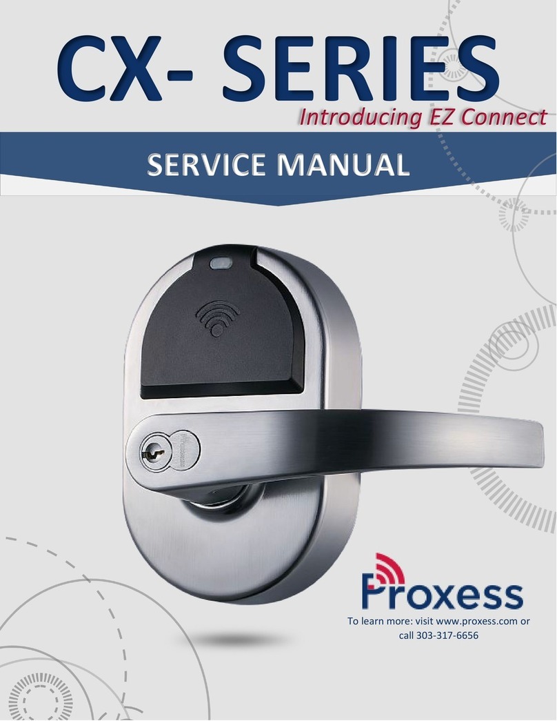
CX- SERIES
SERVICE MANUAL
Introducing EZ Connect
To learn more: visit www.proxess.com or
call 303-317-6656

2
CX-Series Service Manual
CX-SERIES INSTALLATION INSTRUCTIONS
A. CHECKLIST (4 AA Batteries Included)
Parts List: Each Proxess CX-Series lockset includes
•Door Preparation Template
•Cylindrical Lever Lockset with Installation Instructions
•Exterior lock assembly (include housing, lever and cylinder drive unit)
1. Keys
2. Removeable Core
3. Exterior Lever
4. Exterior housing (includes plastics and light pipes)
5. Exterior Rose
6. Chassis plate
7. Chassis
8. Through Bolt Posts
9. Exterior Backplate
10. Ribbon Cable
11. Exterior Assembly Screws
12. Exterior Gasket
•Hardware box includes:
13. Latch
14. ASA Strike Plate
Screw Pack includes:
▪(SP1) Hager mounting screws M5 x 38mm x4pcs
▪(SP2) Flat head tapping screws #8x3/4" x2pcs
▪(SP3) Flat head tapping screws #12-24 x 18mm x2pcs
▪(SP4) Lever release tool
▪(SP5) Hager mounting screws M6 x 10mm x2pcs (optional)
▪(SP6) Torx Wrench and Optional Torx Security Screw
•Interior lock assembly
15. Interior Gasket
16. Interior Backplate
17. Interior Backplate Screws
18. Interior Rose
19. Interior Housing
20. Interior Housing Screws
21. Battery Cover
22. Battery Cover Standard Screw
23. Interior Lever
FOR DOOR AND FRAME PREPARATION INSTRUCTIONS, SEE APPENDIX A OR GO TO PROXESS.COM
SP1
SP2
SP3
SP5
SP4
SP6

3
CX-Series Service Manual
B. ADJUST FOR DOOR THICKNESS
Remove through bolt posts from chassis. Pull chassis and rose mounting plate from exterior lock assembly.
1. Please follow the steps below:
a. Rotate exterior rose mounting plate toward cylindrical chassis.
b. Put the lever release tool into the allocated position of exterior rose mounting plate per the illustration below.
c. Rotate exterior rose mounting plate to door thickness by using the lever release tool.
C. LOCK HANDING AND REHANDING (IF NECESSARY)
Determine the hand of your door. The product is set up for Right Hand by default.
Anti-Rotation Tabs on
the rose mounting plate
PLEASE NOTE THAT THE LOCK BODY COMES
PRE-SET TO ACCOMMODATE A 1¾ INCH DOOR

4
CX-Series Service Manual
D. Hardware Installation Steps
STEP 1
STEP 4 (To Re-hand if Necessary)
Install the latch in the door with the SP2 screws provided. The
latch tube prongs should project into the chassis hole.
1. To re-hand the lock chassis, begin by removing both
the through bolt posts. See arrows below.
2. Remove the lock chassis and rotate both the internal
mechanics and the chassis 180 degrees to
accommodate the hand of the door. You will not need
to remove the exterior gasket or backplate.
3. Replace through bolt posts.
STEP 2
Install the strike plate with the SP3 screws provided, checking
to make sure that the position of the deadlocking plunger is
aligned against the strike plate. See Appendix A for additional
Door Preparation instructions.
STEP 3
STEP 5
Ensure the cable from the exterior board is properly routed
through the cylindrical lock chassis by first inserting one edge,
then pressing the other into the cable slot.
Slide the lock chassis through the chassis hole in the door,
ensuring that the chassis engages the latch.
Re-handed lock chassis to
accommodate left-handed door

5
CX-Series Service Manual
STEP 6
STEP 8
Place the back plate on the interior of the door with the upper
and lower screws near the chassis. Route the chassis cable
through the square hole, and the exterior cable through the
upper oval hole.
Connect the chassis, exterior, and handle switch cables to the EZ
connect board, leaving the exterior connection (6 pin rightmost
connection) for the last connection. Ensure all cables are
neatly tucked into the retaining clips on the rose plate.
*RS-485 Option boards will have a 4th cable to connect to the
EZ Connect board located on the left side of the board.
STEP 6B Deadbolt Configuration
For information about installing the Proxess Cylindrical Lockset
with a deadbolt, see “Door Preparation and Installation” in the
CX-Series Service Manual available at proxess.com.
STEP 7
STEP 9
Place the interior rose liner on the interior back plate and screw
in. Route the chassis cable through the square hole in the rose
liner, and the exterior and handle switch cables through the
upper oval hole (the handle switch will route through the lower
oval hole for other than default handing).
Install the interior trim onto the back plate. The boards will plug
into one another when placed correctly. Screw the interior trim
onto the back plate using the two screws on the right and left of
the battery compartment.
Exterior
connector
Handle switch
connector
Chassis
connectors

6
CX-Series Service Manual
STEP 10
STEP 12
Install the four AA batteries, beginning with the outer two.
After the batteries are properly installed, the lock should beep
once and the motor will run. The lock is then in the locked
position.
Install the levers onto the outside and inside of the door. See
tips for installing and removing exterior handle in the CX-Series
Service Manual prior to installation.
STEP 11
STEP 13 (If Necessary)
Screw the battery cover onto the trim.
Install the removable core.
Once the removable core is aligned with the forked pin in the
lock, insert the control key and turn clockwise 15 degrees to
retract the locking lug, then insert the core into the lever. Turn
the control key back counterclockwise 15 degrees to engage the
core and remove the key.
E. Now that the hardware is installed, see “Software Solutions” in this manual to locate your
software resources and begin programming.
Insert first
Insert last
Align with prongs
of forked pin

7
CX-Series Service Manual
APPENDIX A: INSTRUCTIONS FOR DOOR AND FRAME PREPARATION OF CYLINDRICAL LOCK
A. CHECKLIST
Tools for Door Preparation
•Drill
•Drill Bits: 1” (31/32” for drive in latch), 5/16”
•Hole Saw: 2-1/8”
•Phillips Screwdriver, #2
•Hammer
•Chisel
B. DOOR PREPARATION
1. Doors: Steel or Wood
2. Door thickness range: 1-3⁄8" (35mm) ~ 2" (51mm).
3. Match the Backset of your Proxess CX-Series lockset to the corresponding installation (either 2-3⁄8" [60 mm] or 2-3⁄4" [70
mm] Backset).
4. Place the installation template onto the door and mark holes. Drill the 2 1⁄8" (54 mm) first, then drill the two 5/16" (8mm)
holes for lock chassis mounting. Drill the 1" (25 mm) cross bore hole for the latch last.
5. Insert latch into 1" hole and hold it parallel to door face, mark outline and remove latch. Chisel 11⁄64" (4.3mm) deep or
until faceplate is flush with the edge of the door. Insert latch into the 1" hole again, making certain that the latch bolt bevel
faces direction of closing door (see section E for Lock Handing).
6. Secure the latch to the door using two #8x3/4" screws (SP2).
NOTE: Removing the through bolt posts from the chassis will decrease the security of the lock, voiding ANSI
Grade 1 rating of the lock.
C. FRAME PREPARATION
1. Close the door and mark the horizontal line aligned to the strike.
2. Measure one half of door thickness from door stop to mark vertical center line of strike. Drill 1" (25 mm) hole, 1/2" (12.7
mm) deep at intersection of horizontal and vertical center lines.
3. Chisel out the jamb 3/32" (2.4mm) deep or until strike is flushed with jamb and then secure the strike to the jamb using two
#12-24 x 1” screws (SP3).
Backset thickness –note
that lock is preset to
standard 1¾ inch door

8
CX-Series Service Manual
ADDITIONAL RESOURCES
SERVICE EQUIPMENT
ENR™
Enrollment Reader and Programmer
MPD Mobile Programming Device
Android Mobile Phone with no Sim Card
OTG On-the-Go Converter
(included with MPD)
SOFTWARE SOLUTIONS FOR LOCKSET PROGRAMMING
For data sheets and user manuals, please visit our website under the “Support Documents & Data Sheets” and Solutions tabs.
LoxIQ™ : A simple, yet powerful, system that requires only the locks and a phone. It is typically implemented in smaller systems of 50
doors/users or less…Expandable to full server system software.
ProxessIQ™ : The robust scalable access control software supporting Proxess Wireless Locksets and Controllers.
Proxess Sync™:Mobile phone app synchronizes changes from the ProxessIQ™ software to locksets across the country.
FCC STATEMENT
This equipment has been tested and found to comply with the limits for a Class A and Class B digital device, pursuant to part 15 of the FCC Rules.
Please see our full CX-Series Service Manual posted on our website for most recent FCC Statements and compliance information.
FCC Caution:
Any changes or modifications not expressly approved by the party responsible for compliance could void the user’s authority to operate this
equipment.
This device complies with part 15 of the FCC Rules. Operation is subject to the following two conditions: (1) This device may not cause harmful
interference, and (2) this device must accept any interference received, including interference that may cause undesired operation.
Industrie Canada l’énoncé
L’émetteur/récepteur exempt de licence contenu dans le présent appareil est conforme aux CNR d’Innovation, Sciences et Développement
économique Canada applicables aux appareils radio exempts de licence. L’exploitation est autorisée aux deux conditions suivantes :
1. L’appareil ne doit pas produire de brouillage;
2. L’appareil doit accepter tout brouillage radioélectrique subi, même si le brouillage est susceptible d’en compromettre le fonctionnement.
FCCID: 2AKUZPXH01
Product Marketing Name: CX- Series Cylindrical Lockset
IC ID: 22335-PXH01
Contains: SH6MDBT50Q
Models (HVINS): PXHO1-CX03-B (Proxess CX-Series Wireless Cylindrical Lockset), PXH01-CX03-DC (Proxess CX-Series DC Powered Lockset), PXH01-
MX02-B (Proxess MX-Series Wireless Mortise Lockset), PXH01-MX02-DF (Proxess MX-Series DC Powered Mortise Lockset)
UL STATEMENT (Pending)
Other manuals for CX Series
1
Table of contents
Other Proxess Lock manuals
Popular Lock manuals by other brands
Mottura
Mottura POWER 541 Instruction and maintenance manual
Creche Innovations
Creche Innovations MicroCool Station mode instructions
Kaba Mas
Kaba Mas Auditcon 52R installation instructions
Kaba Mauer
Kaba Mauer Varios E 70171 Mounting instructions
IKEA
IKEA ROTHULT manual
AmazonBasics
AmazonBasics Travel Sentry AB-TL100 quick start guide
