Proxess CX Series User manual

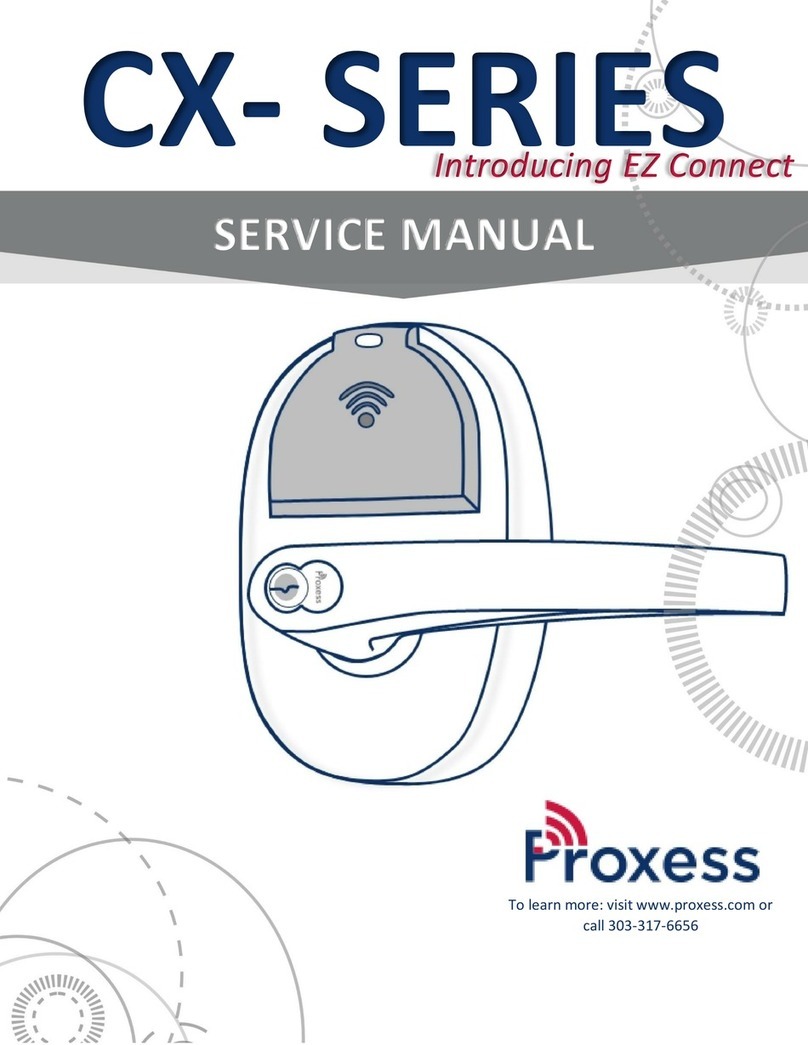
CX- SERIES
SERVICE MANUAL
To learn more: visit www.proxess.com or
call 303-317-6656
Introducing EZ Connect

2
CX-Series Service Manual
TABLE OF CONTENTS
INTRODUCTION 3
Certifications and standards 3-A
Technical support 3-B
FUNCTIONS 4
Construction Function 4-A
Programmable Functions 5-B
Cylindrical Functions Chart 5-C
LOCK PARTS 6
Exploded view of parts 6-A
Parts list 6-B
Trim parts 7-C
MAINTENANCE 9
Maintenance tools 9-A
Replacing levers 9-B
DOOR PREPARATION AND INSTALLATION 10
Cylindrical Installation Jigs 10-A
Through-Bolt Drill Jig 10-B
Deadbolt Door Configuration 10-C
TROUBLESHOOTING 11
Troubleshooting hardware 11-A
INSTALLATION MANUAL 12
CX-Series Installation Instructions 12
ADDITIONAL RESOURCES 18
Service Equipment 18-A
Software Solutions for Lockset Programming 19-B
FCC Statement 20
UL Statement 20
This Service Manual contains details for the Proxess CX-
Series Lockset sold for 2021 (CX-B and CX-NB). For details
about the CX-Series locksets sold prior to 2021 (CX-ST) please
contact a Proxess representative or email info@proxess.com.

3
CX-Series Service Manual
COPYRIGHT
Copyright ©2018 Proxess, LLC. All rights reserved. Printed in the United States of America. Information in this document is subject to
change without notice and does not represent a commitment on the part of Proxess, LLC. The software described in this document
are furnished under a license agreement or nondisclosure agreement. This publication is intended to be an accurate description and
set of instructions pertaining to its subject matter. However, as with any publication of this complexity, errors or omissions are
possible. Please call Proxess corporate offices at (303) 317-6656 if you see any errors or have any questions. No part of this manual
and/or databases may be reproduced or transmitted in any form or by any means, electronic or mechanical, including photocopying,
recording, or information storage and retrieval systems, for any purpose, without the express written permission of Proxess, LLC.
This document is distributed as is, without warranty of any kind, either express or implied, respecting the contents of this book,
including but not limited to implied warranties for the publication’s quality, performance, merchantability, or fitness for any
particular purpose. Neither Proxess, LLC nor its dealers or distributors shall be liable to the user or any other person or entity with
respect to any liability, loss, or damage caused or alleged to be caused directly or indirectly by this publication.
INTRODUCTION
The Proxess CX-Series Service Manual contains important information to assist you in maintaining your Proxess
Cylindrical Lockset.
CERTIFICATIONS AND STANDARDS (CX 2.5 Currently, 3.0 Pending)
ANSI/BHMA A156.25 (Indoor/Outdoor)
ANSI/BHMA A156.2 Grade 1
UL 294
ULC S319 PDR
UL10C Positive Pressure Rated
UL10B Neutral Pressure Rated
FCC Part 15
ADA Compliant
RoHS
Industry Canada (IC)
ETSI EN 300 330-1
ETSI EN 301 489-1
ETSI EN 301 489-3
CENELEC EN 61000-6-3
IEC61000-4-2 ESD Immunity
CENELEC EN 50130-4
TECHNICAL SUPPORT
The first source for technical answers is this CX Series Service Manual. All documentation and training materials
are also available on our website: www.proxess.com. If you are not able to find an answer in these resources,
contact your local Proxess Representative. If you do not know your local Proxess Representative, contact the
Customer Service Department at Proxess (303)-317-6656.
3-A
3-B
3-B

4
CX-Series Service Manual
FUNCTIONS
CONSTRUCTION FUNCTION
All locks are supplied in Construction Function as a default and functions are meant to be reprogrammed at customer site
prior to installation. There is one SKU (standard button) for all functions creating an inventory advantage over standard
mechanical locks.
CC – Construction Function: Factory default setting. In Construction Function, factory programmed construction
credentials granted access at the lockset to allow for testing prior to site programming. Upon first programming of the
lock, the lock will switch to Program Lock Function. A system ID will be set by the site system allowing all credentials
assigned to the site system access until the lock is reprogrammed.
Inside lever is always unlocked for single action egress.
Shading indicates that
the lever is locked.
4-A
All lock functions (Entrance, Storeroom,
Lockdown, etc) are easily programmed
electronically.
Inside
Outside
View looking down at
the top of the door

5
CX-Series Service Manual
PROGRAMMABLE FUNCTIONS
Unlike standard locks, Proxess has just one SKU allowing any lock to be supplied and programmed into numerous lock
“functions” similar to standard locking functions shown in the chart below.
Name
Similar ANSI #
Mech
Proxess Electronic Equivalent Function
Entrance
F109
Enable toggle schedule and double present
credential to outside reader to lock/unlock door
Storeroom
F86
A valid credential should provide momentary
unlocking and allow entry by that user, with the
latch relocking in an administrator defined time
(usually 5-8 seconds)..
Office
F82
A valid credential should provide momentary
unlocking and allow entry by that user, with the
latch relocking in an administrator defined time
(usually 5-8 seconds)..
Classroom no Lockdown
F84
Enable toggle schedule and double present
credential to outside reader to lock/unlock door.
Classroom w/Lockdown
(Intruder)
F110
Enable toggle schedule and double present
credential to outside reader to lock/unlock door.
Lockdown performed by gesture.
Classroom w/Holdback
F85
Enable toggle schedule and double present
credential to outside reader to lock/unlock door.
(electronic equivalent to F84, because unlocked
door allows free entry). There is no Holdback.
Canadian Function
Select toggle mode in the ACS and depress internal
button to toggle the lockset from lock/unlock.
Patio
F77
Select toggle mode in the ACS and depress internal
button to toggle the lockset from lock/unlock.
Secured Privacy
Select toggle mode in the ACS and depress internal
button to toggle the lockset from lock/unlock.
Hotel Guest Room
F93
A valid credential should provide momentary
unlocking and allow entry by that user, with the
latch relocking in an administrator defined time (no
visual indicators)
Dormitory
F90
Select toggle mode in the ACS and depress internal
button to toggle the lockset from lock/unlock.
Service Station
F92
Enable toggle schedule and double present
credential to outside reader to lock/unlock door.
Exit Latch
F89
Mechanical lockset
Privacy
F76
Mechanical lockset
Passage
F75
Mechanical lockset
5-B
5-C

6
CX-Series Service Manual
LOCK PARTS
B FUNCTION CHASSIS – STANDARD
ITEM
PART NUMBER
DESCRIPTION
1
C10-0040A
Control Key
2
A00-0001A
Removeable Core
3
C00-0001A
Exterior Lever
4
C00-0006B
Exterior Trim
5
C00-0016A
Exterior Rose
6
C00-0012A
Chassis Plate
7
C00-0011A
Chassis Housing
8
C00-0041A
Through Hole Posts
9
C00-0018A
Exterior Backplate
10
C00-0021B
6-Pin Ribbon Cable
11
C00-0036A
Exterior Trim Screws
12
C00-0020A
Exterior Gasket
ITEM
PART NUMBER
DESCRIPTION
13
C01-0031A
Latch
14
C02-0030A
Strike Plate
15
C00-0019A
Interior Gasket
16
C00-0017A
Interior Backplate
17
C00-0037A
Interior Screws
18
C00-0015C
Interior Rose
19
C00-0007B
Interior Trim
20
Interior Trim Screws
21
C00-0005B
Battery Cover
22
C00-0038B
Battery Cover Screw
(Standard or Security)
23
C00-0002A
Interior Lever
6-A
6-B

7
CX-Series Service Manual
TRIM PARTS
LATCH BACKSETS
ITEM
PART NUMBER
DESCRIPTION
B1
C01-0030A
2 3/4" (Standard)
B2
C02-0030A
2 3/8” Round Edge
B3*
C03-0030A
2 3/4” Drive-in & No Faceplate
B4*
C04-0030A
2 3/8” Drive-in
B5*
C05-0030A
5”
B6*
C06-0030A
3 3/4”
*Special Order
LATCHES
Optional latch extensions
7-C
5” Backset (70mm) latch + 57mm extension
tube for 5" (127mm) requirement
3 ¾” Backset (60mm) latch + 35mm extension tube
for 3¾" (95mm) requirement
B1
B2
B3
B4
B5
B6

8
CX-Series Service Manual
STRIKE PLATES
ITEM
PART NUMBER
DESCRIPTION
S1
C01-0030A
2 ¾" strike
S2
C02-0030A
ANSI 4 ⅞" strike (Standard)
LEVERS
ITEM
PART NUMBER
DESCRIPTION
6
C06-0001A
Angled Return
8
C08-0001A
Curved Return (Standard)
9
C09-0001A
Curved No Return; (no lever return)
6
8
9
S1
S2

9
CX-Series Service Manual
MAINTENANCE
TOOLS FOR MAINTENANCE
REPLACING LEVERS
TO REMOVE THE LEVER
1. If removing the exterior lever, first remove the removable core by inserting the control key and turning it 15
degrees clockwise. Then, pull out the removable core and key.
2. Line up the mechanism on the inside of the lock where the core was removed with a core turn knob tool.
3. Insert the pin of the lever release tool into the small hole at the base of the shaft on the lever.
4. Push in and then slide the lever off the sleeve of the lever shaft.
TO REPLACE THE LEVER
1. Position the lever so the handle points towards the door hinges.
2. Slide the lever onto the lock and push firmly until it is seated. If the lever does not easily seat, move the throw
member with the core turn knob tool.
3. If replacing the exterior lever, reinstall the removable core by aligning the throw member (forked prongs) within
the lock chassis and then sliding the core back in place. Turn the control key 15 degrees counterclockwise and
remove the key.
4. Turn both levers to make sure they retract the latch if the door is unlocked.
Lever Release Tool
(Included with lock)
Philips Screwdriver, #2
Lever release tool
Lever shaft
Core Turn Knob Tool
Cylinder and Core
Testing Wrench
9-A
9-B
Torx Wrench
(Included with lock)
6-pin or 7-pin removeable cores
allow for added security and
painless re-key.
Proxess cores are stamped with
your custom key code to make
ordering simple and reliable.
Lockset can be quickly installed
with only a Philips Screwdriver.

10
CX-Series Service Manual
DOOR PREPARATION AND INSTALLATION
CYLINDRICAL INSTALLATION JIG KITS
Light-duty, small quantities: Home improvement stores such as Home Depot and Lowes sell inexpensive kits from Ryobi,
Milwaukee and DeWalt.
Heavy-duty, industrial: Pro-Lock (“Killer Jig”) and Templaco (115-C3) offer kits.
THROUGH-BOLT DRILL JIG A00-0002A
For retrofit doors that do not already have standard ADA lever holes, Proxess offers the
A00-0002A jig to assist in drilling holes for added stability and security of the CX product.
NOTE: Removing the through bolt posts from the chassis will decrease the security of the
lock, voiding ANSI Grade 1 rating of the lock.
DEADBOLT DOOR CONFIGURATION
To mount the Proxess cylindrical lockset on a door with a deadbolt installed, you will need to mount the internal housing
(battery side) upside down. The backplate and rose plate are designed to accommodate this mounting.
STEP 1
STEP 2
STEP 3
Position the backplate on the interior
of the door so that the large opening
is underneath the chassis assembly.
Route the cable and wires through
the oval holes in the backplate. Make
sure to run all cables through the
oval holes in both backplate and rose
plate.
NOTE: Wire paths may differ
according to handing.
Fasten to the door using the upper
and lower screws nearest the chassis.
10-A
10-B
10-C

11
CX-Series Service Manual
TROUBLESHOOTING
TROUBLESHOOTING HARDWARE
The following table illustrates possible causes and solutions for common troubleshooting after installing the lock
hardware.
PROBLEM
CAUSE
SOLUTION
No beeps or blinks when the
batteries are installed
Improper plug connection
Check all wiring and connectors to make
sure the connectors are secure, and the
cable is not pinched
Reversed battery or dead
batteries
Check the position of the batteries to make
sure they are seated correctly
Pinched wires or damaged
cabling
Ensure the internal cabling is routed properly
and cables have not been damaged during
assembly
LED does not beep or blink on
exterior when credential is
presented
Batteries are dead and need to be
replaced
Replace the batteries, synchronized the lock
with the MPD and try the credential again
Damaged or disconnected 6 pin
cable
Check both ends of the 6-pin cable for
proper connection.
MPD does not connect to the lock
Bluetooth is not enabled on the
MPD
Enable Bluetooth in Settings
Red LED When credential is
presented (Access Denied).
Improper Credential Permissions
Ensure the credential has appropriate
access to the door.
Lockset is in Lockdown
Have administrator take the lockset out of
lockdown, or program the necessary
credential to have “Pass-Through”
privileges. (See software manual).
BEEP AND BLINK GUIDE
Operation indicators (Usually non-repeating) Description
3 Red Beep/Blinks
The lockset has been set to toggle unlocked.
3 Green Beep/Blinks
The lockset has been set to toggle locked.
Warning Indicators (Will continue until problem
resolved)
Description
3 Red Blinks (No Beeping)
Battery Low
3 Amber Beep/Blinks
Battery Critical
3 Double-Red Beep/Blinks
Battery Critical
3 Double-Red Beep/Blinks
Lockset Not Synchronized
Start-Up Sequence Beep/Blinks
If a problem with the lockset occurs, there may be a sequence of Beep/Blink indicators during start-up that will help to
determine the problem. These will be 3 short Beep/Blinks followed by a series of longer Beep/Blinks. Please note them
and contact a Proxess customer service representative.
11-A

12
CX-Series Service Manual
CX-SERIES INSTALLATION INSTRUCTIONS
A. CHECKLIST (4 AA Batteries Included)
Parts List: Each Proxess CX-Series lockset includes
•Door Preparation Template
•Cylindrical Lever Lockset with Installation Instructions
•Exterior lock assembly (include housing, lever and cylinder drive unit)
1. Keys
2. Removeable Core
3. Exterior Lever
4. Exterior housing (includes plastics and light pipes)
5. Exterior Rose
6. Chassis plate
7. Chassis
8. Through Bolt Posts
9. Exterior Backplate
10. Ribbon Cable
11. Exterior Assembly Screws
12. Exterior Gasket
•Hardware box includes:
13. Latch
14. ASA Strike Plate
Screw Pack includes:
(SP1) Hager mounting screws M5 x 38mm x4pcs
(SP2) Flat head tapping screws #8x3/4" x2pcs
(SP3) Flat head tapping screws #12-24 x 18mm x2pcs
(SP4) Lever release tool
(SP5) Hager mounting screws M6 x 10mm x2pcs (optional)
(SP6) Torx Wrench and Optional Torx Security Screw
•Interior lock assembly
15. Interior Gasket
16. Interior Backplate
17. Interior Backplate Screws
18. Interior Rose
19. Interior Housing
20. Interior Housing Screws
21. Battery Cover
22. Battery Cover Standard Screw
23. Interior Lever
FOR DOOR AND FRAME PREPARATION INSTRUCTIONS, SEE APPENDIX A OR GO TO PROXESS.COM
SP1
SP2
SP3
SP5
SP4
SP6

13
CX-Series Service Manual
B. ADJUST FOR DOOR THICKNESS
Remove through bolt posts from chassis. Pull chassis and rose mounting plate from exterior lock assembly.
1. Please follow the steps below:
a. Rotate exterior rose mounting plate toward cylindrical chassis.
b. Put the lever release tool into the allocated position of exterior rose mounting plate per the illustration below.
c. Rotate exterior rose mounting plate to door thickness by using the lever release tool.
C. LOCK HANDING AND REHANDING (IF NECESSARY)
Determine the hand of your door. The product is set up for Right Hand (LHR) by default.
Anti-Rotation Tabs on
the rose mounting plate
PLEASE NOTE THAT THE LOCK BODY COMES
PRE-SET TO ACCOMMODATE A 1¾ INCH DOOR

14
CX-Series Service Manual
D. Hardware Installation Steps
STEP 1
STEP 4 (To Re-hand if Necessary)
Install the latch in the door with the SP2 screws provided. The
latch tube prongs should project into the chassis hole.
1. To re-hand the lock chassis, begin by removing both
the through bolt posts. See arrows below.
2. Remove the lock chassis and rotate both the internal
mechanics and the chassis 180 degrees to
accommodate the hand of the door. You will not need
to remove the exterior gasket or backplate.
3. Replace through bolt posts.
STEP 2
Install the strike plate with the SP3 screws provided, checking
to make sure that the position of the deadlocking plunger is
aligned against the strike plate. See Appendix A for Door
Preparation Instructions.
STEP 3
STEP 5
Ensure the cable from the exterior board is properly routed
through the cylindrical lock chassis by first inserting one edge,
then pressing the other into the cable slot.
Slide the lock chassis through the chassis hole in the door,
ensuring that the chassis engages the latch.
Re-handed lock chassis to
accommodate left-handed
(RHR) door

15
CX-Series Service Manual
STEP 6
STEP 8
Place the back plate on the interior of the door with the upper
and lower screws near the chassis. Route the chassis cable
through the square hole, and the exterior cable through the
upper oval hole.
Connect the chassis, exterior, and handle switch cables to the EZ
connect board, leaving the exterior connection (6 pin rightmost
connection) for the last connection. Ensure all cables are neatly
tucked into the retaining clips on the rose plate.
*RS-485 Option boards will have a 4th cable to connect to the
EZ Connect board located on the left of the board. (edited)
STEP 6B Deadbolt Configuration
For information about installing the Proxess Cylindrical Lockset
with a deadbolt, see “Door Preparation and Installation” in the
CX-Series Service Manual available at proxess.com.
STEP 7
STEP 9
Place the interior rose liner on the interior back plate and screw
in. Route the chassis cable through the square hole in the rose
liner, and the exterior and handle switch cables through the
upper oval hole (the handle switch will route through the lower
oval hole for other than default handing).
Install the interior trim onto the back plate. The boards will plug
into one another when placed correctly. Screw the interior trim
onto the back plate using the two screws on the right and left of
the battery compartment.
Exterior
connector
Handle switch
connector
Chassis
connectors

16
CX-Series Service Manual
STEP 10
STEP 12
Install the four AA batteries, beginning with the outer two.
After the batteries are properly installed, the lock should beep
once and the motor will run. The lock is then in the locked
position.
Install the levers onto the outside and inside of the door. See
tips in CX-Series Service Manual for exterior handle installation
and removal prior to installation.
STEP 11
STEP 13 (If Necessary)
Screw the battery cover onto the trim.
Install the removable core.
Once the removable core is aligned with the forked pin in the
lock, insert the control key and turn clockwise 15 degrees to
retract the locking lug, then insert the core into the lever. Turn
the control key back counterclockwise 15 degrees to engage the
core and remove the key.
E. Now that the hardware is installed, see “Software Solutions” in this manual to locate your
software resources and begin programming.
Insert first
Insert last
Align with prongs
of throw member
(forked pin)

17
CX-Series Service Manual
APPENDIX A: INSTRUCTIONS FOR DOOR AND FRAME PREPARATION OF CYLINDRICAL LOCK
A. CHECKLIST
Tools for Door Preparation
•Drill
•Drill Bits: 1” (31/32” for drive in latch), 5/16”
•Hole Saw: 2-1/8”
•Phillips Screwdriver, #2
•Hammer
•Chisel
B. DOOR PREPARATION
1. Doors: Steel or Wood
2. Door thickness range: 1-3⁄8" (35mm) ~ 2" (51mm).
3. Match the Backset of your Proxess CX-Series lockset to the corresponding installation (either 2-3⁄8" [60 mm] or 2-3⁄4" [70
mm] Backset).
4. Place the installation template onto the door and mark holes. Drill the 2 1⁄8" (54 mm) first, then drill the two 5/16" (8mm)
holes for lock chassis mounting. Drill the 1" (25 mm) cross bore hole for the latch last.
5. Insert latch into 1" hole and hold it parallel to door face, mark outline and remove latch. Chisel 11⁄64" (4.3mm) deep or
until faceplate is flush with the edge of the door. Insert latch into the 1" hole again, making certain that the latch bolt bevel
faces direction of closing door (see section E for Lock Handing).
6. Secure the latch to the door using two #8x3/4" screws (SP2).
NOTE: Removing the through bolt posts from the chassis will decrease the security of the lock, voiding ANSI
Grade 1 rating of the lock.
C. FRAME PREPARATION
1. Close the door and mark the horizontal line aligned to the strike.
2. Measure one half of door thickness from door stop to mark vertical center line of strike. Drill 1" (25 mm) hole, 1/2" (12.7
mm) deep at intersection of horizontal and vertical center lines.
3. Chisel out the jamb 3/32" (2.4mm) deep or until strike is flushed with jamb and then secure the strike to the jamb using two
#12-24 x 1” screws (SP3).
Backset thickness – note
that lock is preset to
standard 1¾ inch door

18
CX-Series Service Manual
ADDITIONAL RESOURCES
SERVICE EQUIPMENT
ENR™
Enrollment Reader and Programmer
Proxess’ ENR™ makes the credential enrollment process intuitive and simple.
Just place a credential on the desktop reader and a pop-up window
automatically appears. From here you can create a new user, assign this card to
an existing user, or view the details of an existing cardholder.
NX™ Smart Credentials
Network on Card Smart Credentials
Proxess systems utilize the most advanced and flexible credential technology in
the industry, DESFire EV2, and add six layers of protection, encryption and mutual
authentication, providing the most secure credentials in the industry.
MPD Mobile Programming Device
Android Mobile Phone with no SIM Card
The Mobile Programming Device is used with the Proxess LoxIQ™ software to
build door groups, access profiles, time schedules, and so much more. It can also
be used to assign high security Network-on-Card credentials to personalized
profiles with the Proxess Enrollment Reader and On-the-Go Converter. Proxess
software is currently compatible with only Android devices. However, we are
excited to develop software with IOS capabilities. Please check our website for the
latest capabilities for Proxess products.
OTG On-the-Go Converter
The On-the-Go Converter is provided with the Mobile Programming Device and
Enrollment Reader to assign credentials. Proxess offers OTG converters for both
Micro USB and Type C devices.
For additional information about service equipment and Proxess products, please visit our website:
www.proxess.com
18-A

19
CX-Series Service Manual
SOFTWARE SOLUTIONS FOR LOCKSET PROGRAMMING
LoxIQ™
LoxIQ™ is a software app created by Proxess, LLC. Instead of requiring all the expensive components of an
access system (approx. $3k/dr), LoxIQ™ requires only the locks, a phone, and a programmer. Although the
system has the capability of unlimited doors and users, it is typically implemented in smaller systems of 100
doors/users or less…Expandable to full server system software.
For more information about LoxIQ™, please visit our website:
http://www.proxess.com/Proxess/media/Proxess/Images/Graphics/loxiq_datasheet_4pg_06.pdf?ext=.pdf
ProxessIQ™
ProxessIQ™ is the scalable access control software, supporting Proxess intelligent wireless locksets and door
controllers. A ProxessIQ™ system can begin with a single wire-free lockset and incrementally expand to an
unlimited number of locations, doors and users.
For more information about ProxessIQ™, please visit our website:
http://www.proxess.com/Proxess/media/Proxess/Documents/ProxessIQ-Scalable-ACS.pdf?ext=.pdf
Proxess Sync™
The Proxess Sync™ mobile phone App synchronizes changes from the ProxessIQ™ software to locksets across
the country. It is a simple to use configuration App, requiring just a click to perform the synchronizations.
Strictly a performance App, it is secure and uncompromising. The App user simply clicks in Proxess Sync™ to
have the changes securely made on the PC software executed at the lockset.
For more information about Proxess Sync™, please visit our website:
http://www.proxess.com/Proxess/media/Proxess/Images/Solutions/Proxess-Sync-DS-Pg-1-(1).pdf?ext=.pdf
19-B

20
CX-Series Service Manual
FCC STATEMENT
This equipment has been tested and found to comply with the limits for a Class A digital device, pursuant to part 15 of the FCC Rules. These limits
are designed to provide reasonable protection against harmful interference when the equipment is operated in a commercial environment. This
equipment generates, uses, and can radiate radio frequency energy and, if not installed and used in accordance with the instruction manual, may
cause harmful interference to radio communications. Operation of this equipment in a residential area is likely to cause harmful interference in
which case the user will be required to correct the interference at his own expense.
This equipment has been tested and found to comply with the limits for a Class B digital device, pursuant to Part 15 of the FCC Rules. These limits
are designed to provide reasonable protection against harmful interference in a residential installation. This equipment generates, uses, and can
radiate radio frequency energy and, if not installed and used in accordance with the instructions, may cause harmful interference to radio
communication. However, there is no guarantee that interference will not occur in a particular installation. If this equipment does cause harmful
interference to radio or television reception, which can be determined by turning the equipment off and on, the user is encouraged to try to
correct the interference by one of the following measures:
Reorient or relocate the receiving antenna.
Increase the separation between the equipment and receiver.
Connect the equipment into an outlet on a circuit different from that to which the receiver is connected.
Consult the dealer or an experienced radio/TV technician for help.
FCC Caution:
Any changes or modifications not expressly approved by the party responsible for compliance could void the user’s authority to operate this
equipment. This device complies with Part 15 of the FCC Rules. Operation is subject to the following two conditions: (1) This device may not cause
harmful interference, and (2) this device must accept any interference received, including interference that may cause undesired operation.
User Manual Notice required by Section 8.4 of ISED RSS-Gen Issue 5
Industry Canada Statement
This device contains licence-exempt transmitter(s)/receiver(s) that comply with Innovation, Science and Economic Development Canada’s licence-
exempt RSS(s). Operation is subject to the following two conditions:
1. This device may not cause interference.
2. This device must accept any interference, including interference that may cause undesired operation of the device.
Industrie Canada l’énoncé
L’émetteur/récepteur exempt de licence contenu dans le présent appareil est conforme aux CNR d’Innovation, Sciences et Développement
économique Canada applicables aux appareils radio exempts de licence. L’exploitation est autorisée aux deux conditions suivantes :
1. L’appareil ne doit pas produire de brouillage;
2. L’appareil doit accepter tout brouillage radioélectrique subi, même si le brouillage est susceptible d’en compromettre le fonctionnement.
FCC ID: 2AKUZPXH01
IC: 22335-PXH01
Contains FCC ID: SH6MDBT50Q
Models (HVINS):
•PXHO1-CX03-B (Proxess CX-Series Wireless Cylindrical Lockset)
•PXH01-CX03-DC (Proxess CX-Series DC Powered Lockset)
•PXH01-MX02-B (Proxess MX-Series Wireless Mortise Lockset)
•PXH01-MX02-DF (Proxess MX-Series DC Powered Mortise Lockset)
UL STATEMENT
Outside lever is normally locked. Inside lever always allows egress.
Unit shall not interfere with the operation of Panic Hardware.
Wireless communications, Wi-Fi, Bluetooth, Door Position, and Request to Exit features are not part of UL Listed product.
Tested to compliance with UL 294 5th Edition Class I.
Other manuals for CX Series
1
This manual suits for next models
6
Table of contents
Other Proxess Lock manuals
Popular Lock manuals by other brands
Salto
Salto KPB22 Series quick start guide
Supra
Supra TRAC-Guard Installation & user manual

Yli Electronic
Yli Electronic YM-2400SL quick start guide
Sargent and Greenleaf
Sargent and Greenleaf 6631 Operating and Combinatiion Changing Instructions

Canaropa
Canaropa 9500M Series installation instructions
Q-See
Q-See QSE7F4 user manual
