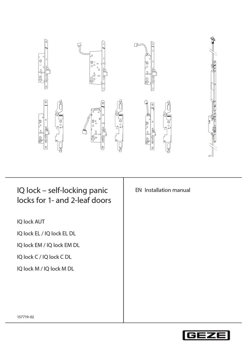
Proxess MX Series User manual

1
To learn more: visit www.proxess.com
or call 303-317-6656
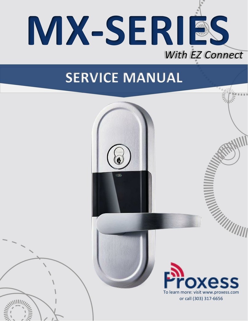
MX-SERIES
SERVICE MANUAL
Introducing EZ Connect

2
TABLE OF CONTENTS
INTRODUCTION 3
DOCUMENTATION PACKAGE 3
CERTIFICATIONS AND STANDARDS 3
TECHNICAL SUPPORT 4
FUNCTIONS 4
LOCK FUNCTIONS LETTER CHART 4
LOCK PARTS 5
PARTS BLOWUP 5
PARTS NUMBER CHART 5
CASE AND STRIKE DIMENSIONS 6
CYLINDER/KEYING 6
TRIM PARTS 7
MAINTENANCE 7
TOOLS FOR MAINTENANCE 7
TROUBLESHOOTING HARDWARE 8
INSTALLATION MANUAL 9
MORTISE INSTALLATION DOOR PREP 10
MORTISE INSTALLATION INSTRUCTIONS 12
MORTISE INSTALLATION TEMPLATE 21
ADDITIONAL RESOURCES 22
SERVICE EQUIPMENT 22
SOFTWARE SOLUTIONS 23
FCC Statement 24

3
COPYRIGHT
Copyright ©2018 Proxess, LLC. All rights reserved. Printed in the United States of America. Information in this document is subject to
change without notice and does not represent a commitment on the part of Proxess, LLC. The software described in this document
are furnished under a license agreement or nondisclosure agreement. This publication is intended to be an accurate description and
set of instructions pertaining to its subject matter. However, as with any publication of this complexity, errors or omissions are
possible. Please call Proxess corporate offices at (303) 317-6656 if you see any errors or have any questions. No part of this manual
and/or databases may be reproduced or transmitted in any form or by any means, electronic or mechanical, including photocopying,
recording, or information storage and retrieval systems, for any purpose, without the express written permission of Proxess, LLC.
This document is distributed as is, without warranty of any kind, either express or implied, respecting the contents of this book,
including but not limited to implied warranties for the publication’s quality, performance, merchantability, or fitness for any
particular purpose. Neither Proxess, LLC nor its dealers or distributors shall be liable to the user or any other person or entity with
respect to any liability, loss, or damage caused or alleged to be caused directly or indirectly by this publication.
INTRODUCTION
The Proxess MX-Series Service Manual contains important information to assist you in maintaining your Proxess Mortise
Lockset.
CERTIFICATIONS AND STANDARD
•ANSI/BHMA A156.25 (Indoor/Outdoor)
•ANSI/BHMA A156.2 Grade 1
•ULC S319 PDR
•ULC Canada
•UL10C Fire-Rated
•UL10B Neutral Pressure Rated
•FCC Part 15 •ADA Compliant
•RoHS •Industry Canada (IC)
TECHNICAL SUPPORT
The first source for technical answers is this MX Series Service Manual. All documentation and training materials are also
available on our website: www.proxess.com. If you are not able to find an answer in this manual, contact your local
Proxess Representative. If you do not know your local Proxess Representative, contact the Customer Service
Department at Proxess (303)-317-6656.

4
LOCK FUNCTIONS
Note: All functions can be programmed so the only two decisions required for stocking is either a deadbolt
or latch-only option.
Please contact Proxess for additional function capabilities.
Name
Similar ANSI # Mech
Proxess Similar Electronic Function
Mortise Latch Functions (Lock Model MX-STL)
Entry/Office
F04
Lock Model MX-STL Select Office mode in
software. Double presentation of credential
locks exterior lever and user will see a triple Red
LED flash indicating exterior lever is locked.
Double presentation of credential again unlocks
exterior lever and user will see a triple Green
LED flash indicating exterior lever is unlocked.
When exterior lever is locked, presenting a valid
credential momentarily unlocks exterior lever.
Inside lever provides free egress.
Classroom Lock
F05
Lock Model MX-STL Select Office mode in
software. External lever locked and unlocked by
double presentation (toggle) of credential within
(programmable) seconds. Inside lever provides
free egress. (Same as entry lock)
Storeroom
F07
Lock Model MX-STL Select Office mode in
software. Exterior lever always locked until a
valid credential provides momentary access.
Inside lever provides free egress.
Mortise w/Deadbolt Functions (Lock Model MX-STB)
Entrance/Office Lock
F21
Lock Model MX-STB Select Office mode in
software. Presentation of a valid credential from
the exterior provides access by releasing both
the latch and deadbolt. Double presentation
(toggle) of credential locks exterior lever and
triple Red LED flash indicates exterior lever is
locked. Double presentation of credential
unlocks exterior lever and a triple Green LED
flash indicates exterior lever is unlocked.
Deadbolt projected by turning inside thumbturn.
External lever locked and unlocked by double
presentation (toggle) of credential within
(programmable) seconds. Inside lever provides
free egress.

5
LOCK FUNCTIONS (CONT.)
Dormitory Lock
F13
Lock Model MX-STB Select Office Mode in
software, Turning inside thumb-turn extends
deadbolt to lock exterior lever from the inside
which locks out all credentials that do not have
Pass-Through rights (housekeeping,
etc.).Exterior lever locked (triple red LED flash)
or unlocked (triple green LED flash) by double
presenting credential. Turning inside lever
provides egress by retracting both the latch and
deadbolt.
Hotel/Motel Lock
F21
Lock Model MX-STB Select Storeroom Mode in
software. Turning inside thumb-turn extends
deadbolt to lock exterior lever from the inside
which locks out all credentials that do not have
Pass-Through rights (housekeeping, etc.).
Exterior lever always locked until credential is
presented to momentarily provide access.
Turning inside lever provides egress by
retracting both the latch and deadbolt.
Hotel or Secure Restroom with
indicator
Contact Proxess to discuss this application.
Mechanical Lock Only Function
Passage/Closet Latchset
F01
Mechanical Lockset offered for this function.
Privacy or Bedroom
F19
Mechanical Lockset offered for this function.
Double Key Functions
*Storeroom (Dual Readers)
F30
BX-EN-POE (for ProxessIQ System), Mini-IQ
(for LoxIQ System) This function requires a dual
reader style entrance if made electronic. The
locking mechanism would be an electric strike.
This door will remain always locked until valid
credential provides momentary access. Reader
provides momentary access independent of
each other.
*Communicating Lock (Dual
Readers)
F14
Contact Proxess to discuss other double lock
applications
*ATTENTION: Functions that secure both sides of the door could violate emergency exit capabilities, and violate life safety codes, potentially creating
hazardous or even fatal consequences.

6

7
LOCK PARTS
PARTS BLOWUP

8
PART NUMBERS AND DESCRIPTIONS
ITEM
PART NUMBER
DESCRIPTION
1
M00-0031A
Cylinder
2
M00-0006A
Exterior Trim
3
M00-0018A
Exterior Backplate
4
M00-0020A
Gasket
5
M00-0013A
Spindle
6
M00-0014A
Spindle Spring
7
M00-0033A
Flat Head Screw (x2)
8
M00-0015A
Spring Cage
9
M00-0013A
Spindle
10
M00-0035A
Set Screw (Long)
11
M00-0037A
Counter Sink Screw (x4)
12
M00-0007A
Interior Trim
13
M00-0036A
Set Screw (Short)
14
M00-0042A
Hex Wrench
15
M00-0016A
Thumb Turn Spindle
16
M00-0038A
Round Hex Screw (x2)
17
M00-0017A
Interior Backplate
18
M00-0008A
Micro-Switch Flipper
19
Latch Monitor Connector
ITEM
PART NUMBER
DESCRIPTION
20
M01-0011A
Mortise Chassis for
Bolt Functions
M02-0011A
Mortise Chassis for
Latch Only
21
Motor Connector
22
M00-0034A
Flat Head Screw (x2)
23
M01-0012A
Chassis Faceplate for
Bolt Functions
M02-0012A
Chassis Faceplate for
Latch Only
24
M00-0039A
Front Panel Screw (x2)
25
M01-0030A
Strike Plate for Bolt
Functions
M02-0030A
Strike Plate for Latch
Only
26
M00-0040A
Strike Plate Screw (x2)
27
M00-0005A
Battery Cover
28
M00-0021B
6-Pin Cable
29
M00-0041A
Trim Fixing Screw
30
M06-0001A
for Angled Return
M08-0001A
For Curved Return
PROXESS MX CASE AND STRIKE DIMENSIONS

2
CYLINDER/KEYING
Due to the extra thick trim that houses RF and battery components, Proxess mortise locks will require special length (1
34
⁄ inch) cylinders. When using other manufacturers’ cylinders, ensure that you have the proper 1 34
⁄ inch long
cylinder.
Proxess locks are supplied with only small format removable cores and we strongly recommend that these locks are
keyed differently than other cylinders in the existing lock system. Keys for Proxess locks are meant to be used only in
emergency situations that require a mechanical key bypass. Proxess software monitors when a mechanical key is used.
Proxess supplies custom keyed cores to match existing Proxess locks/systems. You will see a core mark on the face of
the core. Simply provide your account name and this core mark in order to receive custom “matching” keying. Most
Proxess cores contain several “spool” segments standard as a safeguard to resist picking. The software will notify the
administrator of entry audits when access was gained by a key or in the unlikely event the lock was picked.
TRIM PARTS
STRIKE PLATES
ITEM
PART NUMBER
DESCRIPTION
SL
M02-0030A
Latch only strike plate
SB
M01-0030A
Bolt and latch strike plate
LEVERS
ITEM
PART NUMBER
DESCRIPTION
6
M06-0001A
Angled Return
SL
SB
6
8

7
8
M08-0001A
Curved Return
MAINTENANCE
TOOLS FOR MAINTENANCE
TROUBLESHOOTING HARDWARE
The following table illustrates possible causes and solutions for common problems after installing the lock hardware.
PROBLEM
CAUSE
SOLUTION
No beeps or blinks when the
batteries are installed
Improper plug connection
Check all wiring and connectors to make
sure the connectors are secure, and the
cable is not pinched
Reversed battery or dead
batteries
Check the position of the batteries to make
sure they are seated correctly
Pinched wires or damaged
cabling
Ensure the internal cabling is routed properly
and cables have not been damaged during
assembly
LED does not beep or blink on
exterior when credential is
presented
Batteries are dead and need to be
replaced
Replace the batteries, synchronize the lock
with the MPD and try the credential again
Damaged or disconnected 6 pin
cable
Check both ends of the 6-pin cable for
proper connection.
MPD does not connect to the lock
Bluetooth is not enabled on the
MPD
Enable Bluetooth in Settings
Red LED When credential is
presented (Access Denied).
Improper Credential Permissions
Ensure the credential has appropriate
access to the door.
Lockset is in Lockdown
Have administrator take the lockset out of
lockdown, or program the necessary
credential to have “Pass-Through”
privileges. (See software manual).
Philips Screwdriver, #2
Core Turn Knob Tool
PN#: AX-309
Cylinder and Core Testing Wrench
PN#: AX-609

9
INSTALLATION INSTRUCTIONS
The following pages contain the Installation Manual for the MX- Series Mortise Lock
A. CHECKLIST (4 AA BATTERIES INCLUDED)
Parts List: Each Proxess MX-Series lockset includes
•Door Preparation Template
•Mortise Lever Lockset with Installation Instructions
oExterior lock assembly (include housing, lever and cylinder drive unit)
oInterior lock assembly
oCylinder
•Hardware box includes:
oASA Strike Plate (Deadbolt or Latch Only)
oSpindle Pack Includes:
▪Spindle x4 pcs
▪Thumb Turn Spindle
▪Micro Switch CAM
▪Spindle Spring
▪Round Head Screw x2 pcs
oSpring Cage Pack Includes:
▪Spring Cage x2 pcs
▪Flat Head Screw x4 pcs
oScrew Pack includes:
▪(SP1) Set Screw (Long)
▪(SP2) Set Screw (Short)
▪(SP3) Counter Sink Screw x4 pcs
▪(SP4) Front Panel Screw x2 pcs
▪(SP5) Strike Plate Screw x2 pcs
▪(SP6) Panel Set Screw
▪(SP7) Hex Wrench
BEEP AND BLINK GUIDE
Operation indicators (Usually non-
repeating)
Description
3 Red Beep/Blinks
The lockset has been set to toggle unlocked.
3 Green Beep/Blinks
The lockset has been set to toggle locked.
Warning Indicators (Will continue until
problem resolved)
Description
3 Red Blinks (No Beeping)
Battery Low
3 Amber Beep/Blinks
Battery Critical
3 Double-Red Beep/Blinks
Battery Critical
3 Double-Red Beep/Blinks
Lockset Not Synchronized
Start-Up Sequence Beep/Blinks
If a problem with the lockset occurs, there may be a sequence of Beep/Blink indicators during start-up
that will help to determine the problem. These will be 3 short Beep/Blinks followed by a series of longer
Beep/Blinks. Please note them and contact a Proxess customer service representative.

10
B. Door Preparation
Measure the desired height from the floor to the door handle.
Use the Mortise Lock Installation Template for prepping the Mortise door holes.
•Using the provided template, drill out the proper holes in the door.
oUse a 34
⁄inch hole saw to drill the hole for routing the cables through. If you do not have a hole saw,
use a 12
⁄inch drill bit and drill two holes.
Lock Handing
Note: The lock is right handed by default. To rehand the lock, you will need to change the lock bolt
orientation.

11
C. Left Hand and Right Hand Reverse Set Up (See D for RH and LHR Set Up)
C.1 Latchbolt Orientation Set up
1. Remove the front panel screw (24) and the front panel (23).
2. Then, unscrew the latch set screw.
3. Pull out the latchbolt, turn it 180, and replace it in the chassis.
4. Then, screw back in the set screw.
C.2 Remove Free Wheeling Lever Set Screw
C.3 Proper Spring Cage Orientation Set Up (For Left
Hand or Right-Hand Reverse)
See below. Note: arrow “B” must point down.
Only remove the screw from the reader/ external side of
the Mortise assembly.
1. For Exterior Panel Spring Cage- Place the spring
cage on the exterior side of the trim. Arrow should
point clockwise or in the direction you want the
handle to engage the latch.
2. Then, screw in the two set screws.
For Interior Panel Spring Cage –Arrow should point
counterclockwise.
D. Right Hand and Left-Hand Reverse Setup
Latch set
Screw
Front panel Screw
Free Wheeling Lever Set Screw
Spring Cages

12
D.1 Right Hand and Left Hand Reverse
D.2 Remove Free Wheeling Lever Set Screw
Do not remove the latchbolt.
1. Remove the front panel set screw (24) and the
front panel (23).
See below. Note: Arrow B must point down.
Only remove the screw from the reader/ external side of
the Mortise assembly.
D.3 Proper Spring Cage Orientation Set Up (For Right Hand or Left Hand Reverse)
1. For Exterior Panel Spring Cage- Place the spring cage on the exterior side of the trim. Arrow should point
counterclockwise or in the direction you want the handle to engage the latch.
2. Then, screw in the two set screws.
For interior panel Spring Cage –Arrow should point clockwise.
Screws

13
Hardware Installation
E. Mortise Chassis Installation
1. Route the cables through the door hole. Use pliers if necessary.
2. Slide Latch Monitoring Cable (19) and Motor Cable (20) through the door hole as shown.
3. Then, slide Mortise Lock chassis (20) into the door and screws (22) as shown (Do not fasten screws at this
point). It may be easiest with a second person to hold the chassis.
F. External Panel Installation
F.1 Attaching Hex Bolts and Gasket
Insert Hex Bolts (9) onto
the Exterior Trim (2).
Ensure Ribbon Cable is secure
in Exterior Trim first. Note that
cable cannot be folded.
Then install Exterior
Gasket onto the
Exterior Trim.

14
F.2 Insert Spindle
F.3 Insert Ribbon Cable
1. Insert the spindle (5) and spindle spring (6) into
the spring cage.
Ensure the lever rotates smoothly and drives the spindle
properly.
Having a hard time installing the spindle? Make sure the
handle is 90perpendicular to the trim in the desired
orientation. Shifting the handle slightly may help
particularly troublesome spindles.
NOTE: Pay close attention to the spring. The small spring
is not attached to anything and can be easily misplaced.
1. Insert the ribbon cable into the 5/8” opening on
the side of the door.
2. Pull the ribbon cable through the other side of the
door.
If necessary, use pliers to route the cable. Make sure the
cable is not bent or pinched.
F.4 Insert the Exterior Panel Assembly into the door
(Ensure the handle moves freely)
F.5 Install Interior Backplate
1. Insert the ribbon cable into the Interior Gasket (4) and Interior Backplate (17).
2. Fasten the two screws (16).
Screw
Screw
Ensure This arrow is
pointing down when
installing exterior
housing

15
F.6 Connect Cables
1. Attach Exterior Housing cable to the plug on the left or right side of the EZ connect board
2. Attach the chassis cable to the plug on top of the Ez connect board
3. Tuck away loose cable to avoid it being pinched by interior housing
F.7 Install Cylinder
F.8 Tighten Cylinder and Backplate
1. Loosen the cylinder set screw in the mortise
chassis to insert the cylinder.
2. Insert the cylinder (1) into the front panel and
ensure it sits flush with the front plate.
1. Insert the screwdriver into the side of the Chassis
and then tighten the Mortise Cylinder set
screw(22).
2. Tighten interior backplate (17).
Step F Completed
Cylinder
Cylinder Set Screw
Insert Cylinder
Loosen
Cylinder set
screw

16
G. Interior Assembly Preparation
G.1 Remove Battery Cover
Use Hex Wrench (14) to loosen long (10) and short set
screws (13).
Next remove the battery cover (27).
G.2 Inserting Micro Switch CAM
1. Insert the Micro Switch Cam (18) on the spring cage as shown.
2. Then, move (18) to the right and align it with the spindle slot as shown.
Set Screw (10)
Set Screw (13)

17
G.3 Inserting Spindles
G.4 Engaging the Micro Switch
Insert spindle (5) and spring (6) into the spring cage as
shown.
Note: The spring is not attached to anything and
can be easily misplaced. Use caution when
installing the spring.
Turn the lever to make sure (18) is not touching Micro
Switch.
Step G Completed

18
H. Interior Panel Installation
H.1 Installing Thumb Turn Spindle and Connectors
Insert Thumb Turn Spindle (15).(For this model only)
H.2 Then align the spindles and EZ connect with the
chassis and place it onto the interior backplate.
H. Completed
Turn the lever to ensure proper latch engagement. The latchbolt should retract.
Ensure that the
thumbturn is
horizontal when
the deadbolt is in,
and vertical when
the deadbolt is
out/thrown. (For
this model only)
Other manuals for MX Series
2
Table of contents
Other Proxess Lock manuals
Popular Lock manuals by other brands

Nerival
Nerival Ner 5000LR user manual
BASETech
BASETech 1833947 operating instructions
Trilogy
Trilogy DL2700DB installation instructions
KFV
KFV SIEGENIA A-opener 2.2 operating instructions
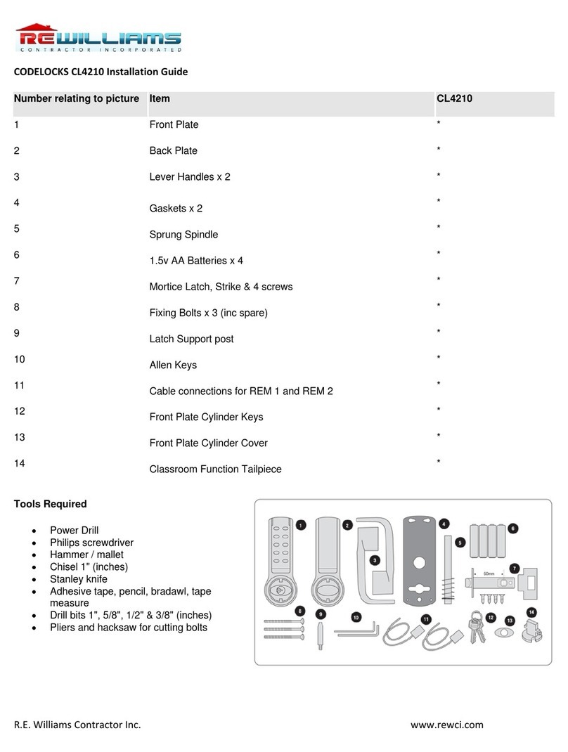
R.E Williams Contractor
R.E Williams Contractor CODELOCK CL4210 installation guide
Mul-t-lock
Mul-t-lock Entr user manual
hune
hune 6000RL-M user manual
VIZpin
VIZpin Grade 1 Cylindrical Smartlock installation instructions
Gantner
Gantner GAT ECO.Side Lock 7000 BA Installation, commissioning & operation
keylezz
keylezz Turn BasicPlus Customer's operating and assembly instructions
ENFORCER
ENFORCER SD-72081-6MQ manual
M-LOCKS
M-LOCKS EuroLine Modular Series user manual
