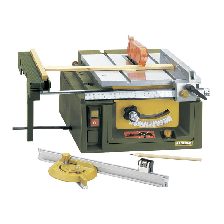
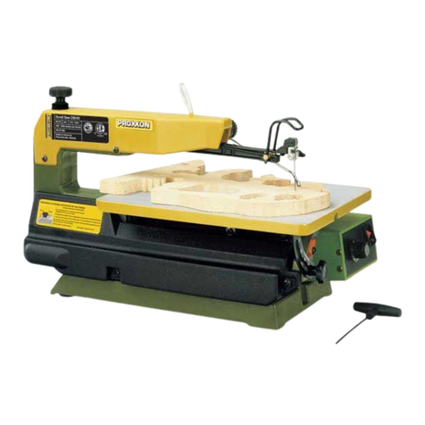
Proxxon FET User manual

7
34567456789
8910 11 12 13 14 15 16 17 18 19 10 11 12 13 14 15 16 17 18 19 20 21 22 23 24
AD
Manual
FET

7
34567456789
8910 11 12 13 14 15 16 17 18 19 10 11 12 13 14 15 16 17 18 19 20 21 22 23 24
7
34567456789
8910 11 12 13 14 15 16 17 18 19 10 11 12 13 14 15 16 17 18 19 20 21 22 23 24
90
80
60
40
20
0
20
40
60
90
AD
20
19
18
17
16
15
14
3
2
4
5
6
7
9
8
10
11
13
12
22 121
Fig. 4
7
34567456789
8910 11 12 13 14 15 16 17 18 19 10 11 12 13 14 15 16 17 18 19 20 21 22 23 24
2
1
3
1
3
45674
910 11 12 13 14 15 16 17 18 19 10 11 1
2
3
2
4
1
3
1
7456789
718 19 10 11 12 13 14 15 16 17 18 19 20 21 22 23 24
2
1
Fig. 2
Fig. 3
Fig. 5
Fig. 1
4
Fig. 5a Fig. 6

18 17 16
3456
15 14 13 12 11 10 9
AD
1
52
34
18 16 15
3456
14 13 12 13 14 15 16
7
17 18 8
4
765
5
432
6
101
7
2
AD
4 3 5
7
34567456789
8910 11 12 13 14 15 16 17 18 19 10 11 12 13 14 15 16 17 18 19 20 21 22 23 24
3
2
4
7
34567456789
8910 11 12 13 14 15 16 17 18 19 10 11 12 13 14 15 16 17 18 19 20 21 22 23 24
2 1
456789
11 12 13 14 15 16 17 18 19 20 21 22 23
1
3
2
Fig. 8a
Fig. 8b
Fig. 9
Fig. 10b
Fig. 7
5
Fig. 10a

Fig. 12
Fig. 10c
6
Fig. 13
Fig. 11
Fig. 14
18 17 16
3456
15 14 13 13 14 15 16
7
17 18 5
4
432
AD
4 3
5 6

17
Contents:
1. In general 17
2. Safety guidelines 17
2.1 Specific safety regulations for circular
saw benches 17
2.2 Safety guidelines regarding protective covers 18
2.3 Safety guidelines for sawing process 18
2.4 Kickback –Causes and corresponding safety
guidelines 19
2.5 Safety guidelines for operating table saws 19
3. Description of machine 20
4. Legend (fig. 1) 20
5. Technical data 20
6. Setting up the saw 21
6.1. Unpacking 21
6.2. Swinging open the upper housing part 21
6.3. Fastening the saw 21
6.4. Saw blade guard 22
6.4.1. Secure the saw blade guard with
the splitting wedge 22
7. Settings 22
7.1. Height adjustment of the saw blade 22
7.2. Adjusting the saw blade tilt 22
8. Extendable saw table 22
9. Dust suction 22
10. Working with the limit stops 23
10.1. Working with the longitudinal stop 23
10.2. Working with the angle stop 23
10.3. Auxiliary stop 23
11.Sawing 23
11.1. General tips on sawing 24
12. Changing the saw blade 24
12.1. Choosing the right saw blade 24
13. Maintenance and repairs: 24
13.1. Cleaning the housing 25
13.2. Cleaning the inside of the device 25
13.3. Replacing the toothed belt 25
14. Disposal 25
15. CE Declaration 25
1. In general
Dear Customer!
The use of these instructions
•makes it easier to become acquainted with the device,
•prevents malfunctions due to improper handling, and
•increases the service life of your device.
Always keep these instructions close to hand.
Only operate this device with exact knowledge of it and comply
with the instructions.
PROXXONwill not be liable for the safe function of the device for:
•handling that does not comply with the usual intended use,
•other application uses that are not stated in the instructions,
•disregard of the safety regulations.
Youwill not have any warranty claims for:
•operating errors,
•lack of maintenance.
For your safety,please comply with the safety regulations at all
costs.
Only use original PROXXON spare parts.
All rights reserved for further developments within the meaning of
technical progress. We wish you much success with the device.
WARNING!
Read all safety warnings and instructions. Failure
to follow all safety warnings and instructions listed
below may result in electric shock, fire and/or serious injury.
KEEP ALL SAFETY WARNINGS AND INSTRUCTIONS FOR
THE FUTURE!
2. Safety guidelines
2.1 Specific safety regulations for circular saw benches
•Donot use deformed or flawed saw blades.
•Replace worn bench inserts.
•Use only the saw blades recommended by Proxxon. Utilised
saw blades must comply with EN 847-1. The saw-cut may
not be smaller than the thickness of the splitting wedge.
•Make sure the saw blade is suitable for the material to be
sawn.
•Wear hearing protection!
•The sawdust from certain materials can be hazardous to
your health. Therefore, wear arespirator.
•Wear gloves when handling saw blades and rough materi-
als!
•Only operate the saw with adust suction device! Your saw
has aconnecting piece at the back for this purpose. Youcan
connect avacuum cleaner here.
•For smaller work pieces, use apush-rod for the feed!
•Never work with adevice that has faulty or defective parts.
Your circular saw might no longer be safe. Therefore, have
any damage immediately repaired by the Proxxon Customer
Service!
GB
Translation of the Original Operating Instructions

•Wear hearing protection! Exposure to noise can cause hear-
ing loss! Make sure that the machine and its accessory
parts are in technically perfect condition! Only the above
establishes the optimal conditions for noisereduction. In
particular,make sure that the saw blade is neither dull nor
damaged. Worn or damaged saw blades have anegative
effect on noise generation and also pose asafety risk! You
can minimize noise generation by adjusting the work piece
feed to the requirements of material and saw blade.
•Saw dust from certain materials can be hazardous to your
health if inhaled or if it touches your skin. For that reason,
always wear appropriate protective clothing (e.g. respirator)
and always work with the suction device. Attention: Dust in
certain concentrations can generate an explosive mixture in
the air!
•Make sure your mains plug has aprotective earthing
conductor and is suitable to operate the device!
2.2 Safety guidelines regarding protective covers
a) Leave the protecting covers assembled. Protecting
covers must be functional and assembled correctly.
Loose, damaged or improperly functioning protecting cov-
ers must be repaired or replaced.
b) For separating cuts, always use the saw blade pro-
tecting cover and the splitting wedge. For separating
cuts where the saw blade cuts through the entire work
piece thickness, the protecting cover and other safety
mechanisms reduce the risk of injuries.
c) Once you have completed your operating procedure
(e.g. groove, back-gouge or separating in reversal
method) which requires the removal of protecting cov-
ers, splittingwedge and/or kickback protection, imme-
diately reinstall the protective system. The protecting
cover,the splitting wedge and the kickback protection
reduce the risk of injuries.
d) Before switching on the power tool, make sure the saw
bladedoes not touch the protecting cover,the splitting
wedge or the work piece.Unintentional contact of these
components with the saw blade can lead to adangerous
situation.
e) Adjust the splitting wedge according to the description
in these operating instructions. Incorrect distances,
position and alignment could be the reason why the split-
ting wedge does not effectively prevent kickback.
f) The splitting wedge and anti-kickback device need to
act on the work piece in order to function. The splitting
wedge and anti-kickback device are ineffective for work
piece sections which are too short for the splitting wedge to
act upon. The splitting wedge and the anti-kickback device
cannot prevent kickback under these conditions.
g) Use the appropriate saw blade for the splitting wedge.
For the splitting wedge to act correctly,the saw blade diam-
eter must match the corresponding splitting wedge, the
steel blade of the saw blade must be thinner than the split-
ting wedge, and the tooth width must be greater than the
splitting wedge thickness.
2.3 Safety guidelines for sawing process
a) DANGER: Your fingers and hands should not come
near the saw blade or within the sawing range. A
moment of carelessness or slipping could direct your hand
towards the saw blade and result in serious injuries.
b) Always guide the work piece against the direction of
rotation of the saw blade. Feeding the work piece in the
same direction as the direction of rotation of the saw blade
above the table can cause the work piece and your hand to
be drawn into the saw blade.
c) Never use the mitre stop to feed the work piece for
long sections, and for cross sections with the mitre
stop, never use the parallel limit stop additionally to
the longitudinal adjustment. Guiding the work piece
simultaneously with the parallel limit stop and the mitre
stop increases the probability that the saw blade will jam
and kickback.
d) For long sections, always exert the feeding force on
the work piece between stop rail and saw blade. Use a
push rod when the distancebetween stop rail and saw
blade is less than 150 mm; use apush block when the
distance is less than 50 mm. Such working aids ensure
that your hand remains at asafe distance to the saw blade.
e) Use only the supplied push rod of the manufacturer,or
one that has been manufactured according to instruc-
tion. The push rod ensures asufficient distance between
hand and saw blade.
f) Never use adamaged or partially cut pushing rod. A
damaged pushing rod can break and cause your hand to
come against the saw blade.
g) Do not work “freehand”. Always use the parallel limit
stop or the mitre stop to position and guide the work
piece. “Freehand” means supporting or guiding the work
piece with the hands instead of with the parallel limit stop
or the mitre stop. Freehand sawing leads to misalignment,
jamming and kickback.
h) Never reach around or over arotating saw blade.
Reaching for awork piece can result in unintentionally
touching the rotating saw blade.
i) Support long and/or wide work pieces behind and/or to
the side of the saw table so they stay horizontal. Long
and/or wide work pieces tend to tilt down at the end of the
saw table; this leads to loss of control, jamming of the saw
blade and kickback.
j)
Guide the work piece evenly.Donot bend or twist the
work piece. If the saw blade jams, immediately shut off
the power tool, disconnect the mains plug and eliminate
the cause of jamming. Awork piece which has jammed the
saw blade can lead to kickback or to blocking of the motor.
k)
Do not remove sawn off material whilst the saw is still
operating. Sawn offmaterial can become fixed between saw
blade and stop rail or in the protecting cover and will pull your
fingersinto the saw blade if you attempt to remove the mate-
rial.Switch offthe saw and wait until the saw blade has come
to acomplete standstill before you remove the material.
18
l) For long sectionsonwork pieces which are thinner
than 2mm, use an additional parallel limit stop that has
contact with the table surface. Thin work pieces can
become wedged under the parallel limit stop and cause
kickback.
2.4
Kickback –Causes and corresponding safety guidelines
Akickback is the sudden reaction of the work piece due to a
catching, jamming saw blade or because awork piece is cut at
an angle in relation to the saw blade, or if part of the work piece
is jammed between the saw blade and parallel limit stop or
other fixed object.
In most cases during akickback, the work piece is caught by
the rear part of the saw blade, lifted up from the saw table and
then flung towards the operator.Kickback is the result of wrong
or faulty use of the table saw.Itcan be avoided by using appro-
priate precautionary measures, as described in the following.
a. Never stand directly in line with the saw blade. Always
keep to one side of the saw blade where the stop rail is
located. During kickback, the work piece can be flung at
highspeeds towards anyone standing in front of and in
linewith the saw blade.
b. Never reach over or behind the saw blade to pull on or
support the work piece. Unintentional contact may occur
with the saw blade, or akickback can cause your fingers to
be pulled into the saw blade.
c. Never hold and press the work piece being sawed
against the rotating saw blade. Pressing the work piece
being sawed against the saw blade will cause jamming
and kickback.
d. Align the stop rail in parallel to the saw blade. An
unaligned stop rail will press the work piece against the saw
blade and generate kickback.
e.
Use afeatherboard when proceeding hidden saw cuts
(e.g. groove, back-gouge or separating in reversal
method). The featherboard allows you to guide the work-
piece against table and longitudinal stop. Afeatherboard
helps you to control the workpiece in case of kickback.
f. Be especially careful when sawing in out-of-sight areas
of assembled work pieces. Adipping in saw blade can
saw into objects that could cause akickback.
g. Support large sheets to minimize the risk of kickback
caused by ajammed saw blade. Large sheets can sag
under their own weight. Sheets need to be supported wher-
ever they extend beyond the table surface.
h. Be particularly careful whilst sawing work pieces
which are twisted, knotted, or warped or do not have a
straight edge to guide them along amitre stop or stop
rail. Awarped, knotted or twisted work piece is unstable
and causes misalignment of the kerf with the saw blade,
jamming and kickback.
i. Never saw work pieces that have been stacked or lined
up in succession. The saw blade could catch one or sev-
eral parts and cause kickback.
j. If you want to restart asaw whose saw blade is still in
awork piece, centre the saw blade in the sawing gap
so that the saw teeth are not caught in the work piece.
If the saw blade is jammed, it can lift up the work piece and
cause akickback when the saw is restarted.
k. Keep the saw blades clean, sharp and sufficiently set.
Never use bent saw blades, or saw blades with cracked
or broken teeth. Sharp and correctly set saw blades min-
imise jamming, blocking and kickback.
2.5 Safety guidelines for operating table saws
a) Switch off the table saw and disconnect it from the
mains before you remove the table insert, replace the
saw blade, carry out settings on the splitting wedge or
the saw blade guard, and whenever leaving the
machine unattended. Precautions serve to prevent acci-
dents.
b) Never leave an operating table saw unattended. Switch
off the power tool and do not leave until it has reached
acomplete standstill. An unattended operating saw rep-
resents an uncontrollable risk.
c) Set up the table saw in an area that is level and well lit
and where you can stand securely and keep your bal-
ance. The set-up site must be spacious enough for you
to comfortably handle the size of your work pieces.
Disarray,non-lit working areas and uneven and slippery
floors can lead to accidents.
d) Regularly remove chips and saw dust underneath the
sawtable and/or from the dust extraction. Accumulated
sawdust is combustible and can self-ignite.
e) Secure the table saw. An improperly secured table saw
can move or fall over
f) Remove adjusting tools, wood scraps etc. from the
table saw before you switch it on. Deflection or possible
jams could be dangerous.
g) Always use the correct size of saw blade and with
matching mounting hole (e.g. diamond-shaped or
round). Saw bladeswhich do not match the assembly
parts of the saw will operate out of centre and will lead to
loss of control.
h) Never use damaged or wrong saw blade assembly
material such as e.g. flanges, flat washers, screws or
nuts. This saw blade assembly material was constructed
specifically for your saw,for secure operation and optimal
performance.
i) Never stand upon the table saw and never use the table
saw as afoot stool. Serious injuries could occur if the
power tool falls over or if you accidentally come into contact
with the saw blade.
j) Ensure the saw blade is always mounted in the correct
direction of rotation. Do not use sanding discs or wire
brushes with the table saw. Improper assembly of the
saw blade or the use of not recommended accessories
can lead to serious injuries.
19

3. Description of machine
The FET table saw is awell thought-out machine for all occur-
ring sawing tasks in the range of small and fine applications.
Apowerful motor,solid mechanics, high-quality materials and
meticulous production make this areliable tool for all possible
sawing applications.
Depending on the utilised saw blades, all types of wood, many
non-ferrous metals, ceramics and plastics as well as many
other materials can be processed with the machine. The cor-
responding saw blades can be obtained from Proxxon and will
be mentioned in more detail later on.
The bench is made of stable aluminium die casting and forms
one unit together with the motor suspension: The guarantees
the highest strength and naturally also affects the precision of
the working results.
To guarantee the highest possible flexibility,weoffer different
types of limit stops that are included with the machine. So
there is something for every application:
There is alongitudinal stop that runs in aguide along the front
of the bench that can be easily shifted and arrested by hand,
or which can be used with the precisely adjustable graduated
scale.
Adjusting capabilities in the tenth of amillimetre range leave
nothing to be desired and make it easy to saw work pieces to
the desired, previously adjusted measure.
In addition there is asophisticated and precise angle stop
which can be extended with an aluminium profile strip with a
moving clamping piece for the exact reproduction of many
parts to be sawed out with equal angles and each with the
same dimensions.
The safety aspect was taken care of as well: The saw blade is
covered by asturdy saw blade guard which automatically
moves up when contact is made with the work piece, and
which only releases as much of the saw blade as necessary.
Caution!
For your own safety,itisunderstood that the saw may never
be operated without this protective guard!
The upper part of the device is hinged so that it can be opened
for cleaning and maintenance purposes. Thus the interior of
the device can be cleaned of chips and dust with avacuum
cleaner,for example. To exclude any kind of hazard, aswitch-
ing contact disconnects the electrics from the power mains
when the upper housing part is open.
But during all cleaning, maintenance and adjusting work (and
of course during sawing) please remember that your FSK is not
aplay toy but atool for woodworking and is thus apotential
source of danger!
Among others apush-rod for the secure feed of more compact
work pieces and two Allen keys are also included in the deliv-
ery.These can be stored in a„key parking slot“ on the right side
of the housing.
In the interests of your own safety,please carefully read
through and comply with the attached safety notes, which are
also mentioned in these instructions, and make sure that you
have also understood them!
4. Legend (fig. 1)
1. Saw blade guard
2. Saw table
3. Saw blade
4. Connection for dust suction
5. Longitudinal stop
6. Key parking slot
7. Rubber connecting piece for suction
8. Allen key
9. Allen key
10. Push-rod
11.Angle stop
12. Knurled screw for fine adjusting
13. Motor unit
14. Angle scale for saw blade tilt
15. Saw blade adjustment for depth of cut
16. Clamping piece
17. Limit stop strip
18. Mains cable
19. On -Off switch
20. Scale for longitudinal stop
21. Extendable saw support
22. Auxiliary stop
5. Technical data
Rotational speed: 7000/min
Saw blade diameter max.: 85 mm
Depth of cut max. (0°): ca. 25 mm
Depth of cut max. (45°): ca. 17 mm
Saw blade drill hole: 10 mm
Splitting wedge thickness: 1.2 mm
Weight: 7kg
Blade body thickness: ≥1mm
Tooth thickness/setting: ≥1.5 mm
Dimensions (in mm):
Width: 300 mm
Depth: 320 mm
Height: 170 mm (with saw blade
guard approx. 220 mm)
Motor:
Voltage: 230 Volt, 50/60 Hz
Power consumption: 200 W
Short-term operation SO
10 min
Noise level: LPA89.7 dB(A)
LWA102.7 dB(A)
Vibration: <2.5 m/s
General measuring uncertainty K=3 dB
Noise/vibration information
The information on vibration and noise emission has been
determined in compliance with the prescribed standardised
and normative measuring methods and can be used to com-
pare electrical devices and tools with each other.
These values also allow apreliminary evaluation of the loads
caused by vibration and noise emissions.
20

Warning!
Depending on the operating conditions while operating the
device, the actually occurring emissions could differ from the
values specified above!
Please bear in mind that the vibration and noise emission can
deviate from the values given in these instructions, depending
on the conditions of use of the tool. This is especially applica-
ble in dependence on the work piece to be machined and the
utilised saw blade and its wear condition. Always ensure you
have an adequately sharp saw blade and awell-maintained
drive. Poorly maintained tools, inappropriate working meth-
ods, different work pieces, too high afeed or unsuitable work
pieces or materials or unsuitable bits and cutters (here: saw
blade) can significantly increase the vibration load and noise
emission across the entire work period.
To more accurately estimate the actual vibration and noise
load, also take the times into consideration where the device
is switched off, or is running but is not actually in use. This can
clearly reduce the vibration and noise load across the entire
work period.
Warning:
•Toreduce vibrations, make sure your tool and the cutting
disc or the saw blade are in proper condition!
•Ensure regular and proper maintenance of your tool
•Stop operation of the tool immediately if excessive vibration
occurs!
•Unsuitable bits and cutters (here e.g. cutting disc or saw
blade) can cause excessive vibration and noises. Only use
suitable bits and cutters!
•Take breaks if necessary when working with the device!
Please note that the sound and vibration measurements in
particular have been performed with Proxxon bits and cutters.
When using third-party brands we cannot guarantee compli-
ance with the statements given here!
Only use in the house
Do not dispose of the device in
household waste
Your fingers and hands should not come near the saw
blade or within the sawing range.
Risk of injury!
Never work without dust protection mask and
safety glasses. Some dusts have ahazardous
effect! Materials containing asbestos may not be machined!
For your safety,always wear hearing protection while
working!
6. Setting up the saw
6.1. Unpacking
Caution!
Please note that transport blocks have been attached to the
device during packing to avoid damage during transportation.
Make sure you remove all of them before commissioning!
Carefully read through the instructions and especially observe
the following chapter!
Atransport block made of cardboard is inserted on the inside
of the saw.This must be removed before initial commissioning.
How to swing up the upper housing part is explained in the
following chapter.
6.2. Swinging open the upper housing part
Caution!
Always use extreme caution if the work requires you to swing
up the upper housing part of the saw: Youcould be injured (e.g.
crush injury) if the upper housing part drops down accidentally
or is closed carelessly!
1. Please open the packaging box to unpack, carefully remove
the saw and deposit it on afirm and level surface.
2. Release the knurled screw 1(fig. 2) and swing up the upper
housing part 2.
3. Permit the latch 3toengage.
4. Before first commissioning, remove the cardboard that was
used as safeguard during the transport.
5. Release the latch 3ofthe support and push the upper hous-
ing part back down. Caution! Hold on to the upper part when
pushing down! Injuries might be caused if the upper part
drops down unchecked.
6. Retighten knurled screw 1.
6.3. Fastening the saw
Attention:
When transporting the saw,the saw blade must be retracted in
the housing (see Chapter 6.1: Height adjustment of the saw
blade). Transport the saw only by carrying it by the housing bot-
tom. Do not hold the attachment parts to carry the saw: These
could break offand cause the saw to drop. Risk of injuries!
Generally the saw must be set up on afixed and level surface,
ideally on aheavy workbench or asolid table. To obtain a
secure hold, your FET should be screwed to the surface: For
this purpose there are four holes in the housing bottom so that
fastening screws can be screwed into them.
Note:
Safe and precise work is only possible with careful fastening!
Therefore, please proceed as follows:
Caution!
Make sure the mains plug is disconnected!
1. Swing up the upper part of the saw
2. Permit the latch to engage
3. Now you can see four hexagonal indentations on the inside
above the four screw holes in the housing bottom, see fig.
3. These are intended to receive M5 hexagon nuts, or the
heads of M5 hexagon screws. Insert sufficiently long screws
2from inside through the opening in the housing bottom and
bolt them through the drill holes that you previously drilled
in the underlay 3.
Use adrilling template for the required hole spacing. Youwill
find asketch with the dimensions at fig. 4.
4. Then release the latch of the support and push the upper
housing part back down.
5. Do not forget to tighten the knurled screw 1(fig. 2)!
21

22
6.4. Saw blade guard
Your FET is equipped with asaw blade guard. It is designed in
such away that moves up as far as necessary during sawing
and then drops back into its home position. It also adapts to the
various adjusted cutting depths.
Caution!
The saw blade guard is an important safety tool and may in no
way be tampered with or even dismantled. Operating the saw
without this guard is dangerous!
While setting up and transporting the saw,always may sure
that the upper saw blade cover is in its correct position. The
free-lying, sharp teeth of the saw blade pose aconsiderable
risk of injury!
6.4.1. Secure the saw blade guard with the splitting wedge
Caution!
For packaging reasons, the saw blade guard and the splitting
wedge are not attached when the device is delivered. However,
assembly is rather simple:
Caution!
Make sure the mains plug is disconnected!
1. Swing open the upper housing part and arrest.
2. Please note that the saw blade in its delivered condition is
in the lower position to guarantee accessibility to the drive
unit. Otherwise, please proceed as explained in the section
„Height adjustment of the saw blade“.
3. If the two screws 1(fig. 5a) are not loose, please release
them slightly with ascrewdriver.Insert the orange-coloured
saw blade guard with the splitting wedge 2inthe saw blade
slot 3and insert behind the little plate clip 4. Please ensure
correct fit: The splitting wedge is seated on the upper of the
two screws 1with its longer cut-out (fig. 5b) up to the limit
stop!Make sure the splitting wedge is fitted correctly in any
case!Only tighten both screws 1afterwards! After you have
tightened the screws, please check once more if the splitting
wedge is seated firmly and if the saw blade can be turned
freely.
4. Push the upper housing part back down and secure with the
knurled screw.
5. Set the desired saw blade position as described further
down in the chapter „Height adjustment of the saw blade“.
7. Settings
7.1. Height adjustment of the saw blade
To adapt the depth of cut, the position of the saw blade can be
regulated in the height. On the one hand, this optimises the
sawing performance, and on the other hand the risk of injury is
reduced due to the restriction of the free saw blade part.
Caution!
Make sure the mains plug is disconnected for all adjusting work!
1. Release the larger knurled button 1(fig. 6) at the front oper-
ating plate and unscrew by afew revolutions
2. The saw blade position can now be set using the smaller
knurled button 2: Turning clockwise will adjust the blade
upwards, and turning counter-clockwise will adjust the blade
downwards.
3. After the desired position is achieved, retighten the knurled
button 1.
7.2. Adjusting the saw blade tilt
The saw blade can be tilted to manufacture mitre cuts. The
desired value is set, or read, with the help of the angle scale.
Caution!
Make sure the mains plug is disconnected for all adjusting
work!
1. Release handwheel 1(fig. 7).
2. Swing the saw blade to the right with the handwheel.
3. Set or read offthe desired angle with indicator 2atthe
angle scale 3.
4. Arrest the saw blade position by turning the handwheel 1
shut
8. Extendable saw table
Caution!
Make sure the mains plug is disconnected for all adjusting
work!
In order to place larger work pieces easily and securely on the
saw table, it has been designed as an extendable saw table.
The extension is quite simple:
Please note:
1. Use your finger to push the curry-coloured limit stop edge 1
(fig. 8a) towards the back. This makes it move out upwards.
2. Pull out the saw table 2with the limit stop edge into the
desired position, see fig. 8b. If necessary,support with the
swivelling lever 3.
3. The small knurled screw 4can be used to clamp the extend-
able saw table into the desired position, as necessary.
4. Now push the limit stop edge 1back into its initial position
to achieve aplane surface. It is now possible to work with
the saw.Please note: The limit stop edge can also be used
for larger work pieces as alongitudinal stop, of course.
5. After completing your work, simply push the extendable
saw table 2back into the initial position. If necessary,fold up
the swivelling lever 3before.
9. Dust suction
At the back of the housing of your FSK you will find acon-
necting piece for dust suction, see fig. 9: avacuum cleaner is
connected here.
This should always be operational while working! Not only
because it guarantees aclean working environment, but also
because this prevents the interior of the saw from becoming
contaminated from sawdust.
The vacuum cleaner hose is simply connected to the rubber
adapter,asshown in the picture.
Here's another tip:
Using the Proxxon CW-matic vacuum cleaner omits that
annoying manual activation and deactivation. The CW-matic is

23
equipped with an automatic control that switches on and off
automaticallywhenever the electrical tool is activated or deac-
tivated.
10.Working with the limit stops
10.1 Working with the longitudinal stop
Assembly (Fig. 10 a):
Is pushed on to the side (from the left or right) over the ruler 5.
Caution:
Locking handle 3and knurled screw 4must be loosened for
this procedure!
Adjusting the longitudinal stop (without fine adjustment
function, Fig 10b):
Is possible on both sides of the saw blade. Is done by simply
shifting and then clamping with locking handle 3.
Important:
The knurled screw 4must be loosened during the adjustment.
Adjusting the longitudinal stop via fine adjustment by
handwheel 7(fig. 10 c):
1. After arough preliminary adjustment, tighten knurled screw
4(toggle screw 3must be loosened).
2. Fine adjustment now follows by turning the handwheel 7
(one rotation moves the limit stop by 1mm).
3. Aftercompleted adjustment it is recommended to fix the
limitstop additionally by tightening the locking handle 3.
Adjusting the zero position of the limit stop scale:
1. Align the longitudinal stop with the left edge 6over the zero
mark of the scale (alternatively left or right).
2. Tighten the knurled screw 4(toggle screw 3must be loos-
ened).
3. Put the longitudinal stop into position via handwheel 7
where the side facing the saw blade hits the outside edge of
the saw blade teeth.
4. The stop can now be aligned with edge 6with the help of the
scale (shows the work piece width in mm).
5. Lock the limit stop after completing positioning by tightening
the locking handle 3.
10.2 Working with the angle stop (Fig. 11)
Caution:
Saw cuts of bevels or wedges must always be made by
using the angular stop!
Assembly:
Push the stop rail 1into the guide of the angle stop and clamp
into the required position with the knurled screw 4.
Using the angle stop (Fig. 12):
Is placed in the designated guides in the table of the FET,
either to the right or left of saw blade 7.
Working with the angle stop without limit stop Fig. 12:
Youabsolutely must ensure sufficient distance of the end of the
stop rail to the saw blade. To do so, disconnect the device
plug and try shifting the limit stop. Warning: The mains plug
must always be disconnected during all adjustment work! Dan-
ger of injuries due to inadvertent starting up!
Working with the angle stop and the limit stop (Fig. 13):
Insert limit stop 8inthe guide of the stop rail and clamp into the
required position with knurled screw 9.
10.3. Auxiliary stop
Appropriate use of the auxiliary stop is made to be able to eas-
ily cut somewhat larger work pieces as well. For this, the saw
table must be extended first, as described in the chapter
„Extendable saw table“; but the limit stop edge is not „sunk“ in
the extendable part by „pressing in“ but simply stays outside.
The distance to the saw blade determines the sawing width,
which can therefore be varied depending on by how much the
saw table is pushed in, or extended. To saw,always fix the limit
stop by tightening the knurled screw.See fig. 8b.
11.Sawing
Caution!
Hold the work piece on the saw table as shown in fig. 14.
Adapt the feed according to the material, the saw blade and the
work piece thickness! Hard materials, fine saw blades and
thick work pieces do not “tolerate” as much feed as soft mate-
rials, rough saw blades and thin materials.
Always operate the saw from the position as shown in Fig. 14a
so that you are always in optimal control of the work piece.
Stand in front of the saw while sawing! Never saw with your
FET from the side or even from the back. Ensure sufficient sta-
bility while you work!
If youprocess correspondingly small work pieces then use the
included push-rod, as shown in fig. 15. This prevents your
hands from coming to close to the revolving saw blade and
thus reduces the risk of injury:
Always keep the push-rod close to hand while working!
If the device is not in use, please use the supplied push-rod in
the designated housing fixture (fig. 14b)!
Please note:
•Only use perfect saw blades.
•Always remove the mains plug for maintenance and upkeep
work.
•Donot let the device operate unsupervised.
When sawing, press the work piece onto the work plate, guide
with sensitivity and with little force, more pressure on the work
plate, less pressure against the saw blade. Guide the work
piece slowly into the saw blade, particularly if the blade is very
thin and the teeth very fine or if the work piece is very thick.

24
11.1. General tips on sawing
For good results, please note the following points:
•When sawing, press the work piece onto the work plate,
guide with sensitivity and with little force; more pressure on
the work plate, less pressure against the saw blade.
•Make sure that the work piece is lying properly on the saw
table (no burrs or sawdust)
•Adapt the feed to the requirements by saw blade, speed and
work piece material.
•Guide the work piece slowly into the saw blade, particularly
if the blade is very thin and the teeth very fine or if the work
piece is very thick.
•Only use perfect saw blades. Make sure that the saw blades
are suitable for use with the FET.You must comply with the
dimensions specified in the technical data.
•Donot let the device operate unsupervised.
•Carefully mark out the check line.
•Make sure there is good lighting.
•Always work with connected dust suction!
•Ifnecessary,use the included push-rod to feed the work
piece.
•Always work with the saw blade guard and splitting wedge.
Make sure that the protective devices are in aperfect
condition.
•Prevent the saw blade from blocking! Always work with
adjusted feed and avoid jamming the work piece. If the saw
blade blocks all the same, please carefully pull out the work
piece against the feed direction so that the saw blade can
rotate freely again.
When sawing plastics, it may happen that the plastic is melted
in the cutting gap of the workpiece due to the friction heat. This
condition is to be avoided by selecting the right saw blade and
the optimum feed.
12. Changing the saw blade
Your saw is equipped with acarbide-tipped saw blade with 36
teeth and an 80 mm diameter ex works.
This is very well suited for most „sawing jobs“, guarantees
clean cuts in the most various materials and guarantees long
service life. But it will not last for ever,ofcourse: Wear will
occur depending on the intensity of use: The saw blade will
become dull, more force to push the work piece is required and
the quality of the cut is reduced, the mechanics of the machine
are stressed more strongly than necessary.
Then it is high time to replace the saw blade with anew one.
It can also be necessary to use adifferent saw blade type for
aparticular task (see also the chapter „Choosing the right saw
blade“ below) so that it needs to be exchanged for the standard
blade. The work steps remain the same, naturally.
1. Disconnect the mains plug!
2. Turn the saw blade down as described in the chapter
„Height adjustment of the saw blade“.
3. Swing open the housing as described in section 6.2
4. To release the screw 1(fig 16a), the shaft on which the saw
blade 2ismounted must be blocked. To do so, insert the
smaller of the two included Allen keys 3through the small
drill hole 4inthe saw table and from there insert it into the
saw blade shaft through across-hole, see fig. 16b. If nec-
essary,this drill hole must be „found“ somewhat by turning
the saw blade by hand. Ahint: For this procedure we rec-
ommend you adjust the saw blade to arelatively high height
and then to lower it somewhat after finding the latching drill
hole with inserted Allen key in order to gain full access to
screw 1.
5. Releasethe cheese-head screw 1with the larger of the two
Allenkeys and remove together with disc 5.
Caution!
The teeth of even worn saw blades are still very sharp! Risk of
injury!
6. Remove the old saw blade upwards and through the saw
blade opening and place the new saw blade on the shaft.
Make sure the saw blade drill hole is seated correctly at the
shaft shoulder!
7. Please also make sure that the teeth are pointing in the
direction as shown in the figures!
8. Screw on disc 5with the cheese-head screw 1and tighten.
Note that the saw shaft still needs to remain blocked with the
small Allen key.
9. Release the latch, push down the upper housing part and
lock with the knurled screw.
12.1. Choosing the right saw blade
Caution!
When choosing the saw blade, make sure at all costs that the
highest permissible speed is sufficiently high enough for the
idling speed of the saw!
The choice of the suitable saw blade has an enormous impact
on the work result: Various characteristics such as work piece
material, saw job intensity and the desired quality of the result
must be considered.Proxxon has different saw blades that
canbeused to operate the machine.
Accessories
For more detailed information on accessories, please request
our device catalogue from the address specified on the last
page in the warranty information.
Please note in general:
Proxxon bits and cutters have been designed to work with our
machines, which makes them optimal for their use.
We will not assume any liability whatsoever for the safe and
proper function of our devices when using third-party bits and
cutters!
13. Maintenance and repairs:
Caution!
Always disconnect the mains plug before doing any cleaning,
setting, maintenance or repair works!
The device is maintenance-free apart from the necessity of
regular cleaning (see below).
Only have repairs carried out by qualified specialist personnel
or,even better,bythe PROXXON central service. Never repair
electrical parts, but always exchange them for original spare
parts from PROXXON!

13.1. Cleaning the housing
For along service life, the device should be cleaned after
every use with asoft cloth, hand brush or asoft brush. Even a
vacuum cleaner can be recommended.
Cleaning the outside of the houses can be done with asoft,
possibly moist cloth. Asoft detergent or other suitable cleaning
agent may be used. Avoid using solvents or alcohol-based
cleaning agents (e.g. benzine, rubbing alcohol, etc.) as these
will affect the plastic housing shells.
If, despite using the dust suction during operation, it is neces-
sary to clean the inside of the device, please simply swing up
the upper housing part and vacuum the inside of the device
with avacuum cleaner.
13.2. Cleaning the inside of the device
Caution!
Never use compressed air for blowing out! The fine wood dust
could become lodged inside the motor or on electrical compo-
nents and impair the reliability and the safety of the machine!
1. Make sure the mains plug is disconnected!
2. Swing open the upper housing part (see also section 6.2
„Unpacking“)
3. Vacuum the inside of the device with avacuum cleaner
4. Push down the upper housing part and lock.
13.3. Replacing the toothed belt
Atoothed belt transmits the power from the motor to the saw
blade shaft. The belt has avery long service life, but when the
machine is used extensively,itcould be necessary to replace
it after alonger operating period. The procedure is described
here. In case you are unsure, please send the saw to our
Central Service.
1. Make sure the mains plug is disconnected!
2. Set the saw blade to an approx. 40° tilt as explained in
section „Adjusting the saw blade tilt“.
3. Swing up the upper housing part as explained in section 6.2
4. Block the shaft with the small Allen key as described in the
Chapter 12.
5.
Unscrew the Phillips screw 1(fig. 17). Remove thrust washer 2.
6. Pull offthe old toothed belt 3and fit the new toothed belt.
Turn the drive at the toothed belt pulleies slightly back and
forth until the new toothed belt sits correctly.
7. Replace the thrust washer 2and tighten with the Phillips
screw 1.
8. Close the upper housing part and correct the saw blade tilt
as desired.
9. Make sure to remove the Allen key for blocking the shaft
before commissioning.
14. Disposal
Please do not dispose of the device in the household waste!
The device contains valuable substancesthat can be recy-
cled.For any further questions, please contact your municipal
disposal company or other appropriate municipal institutions.
15. EC Declaration of Conformity
Name and address:
PROXXON S.A.
6-10, Härebierg
L-6868 Wecker
Product designation: Fine cut circular saw FET
Article No.: 27070
In sole responsibility,wedeclare that this product conforms
to the following directives and normative documents:
EU EMC Directive 2014/30/EU
DIN EN 55014-1 /05.2012
DIN EN 55014-2 /01.2016
DIN EN 61000-3-2 /03.2015
DIN EN 61000-3-3 /03.2014
EU Machinery Directive
2006/42/EC
DIN EN 62841-1/07.2016
DIN EN 62841-3-1/05.2015
DIN EN ISO 14121-1 /09.2010
CE-Type certification according to Macine Guidline
2006/42/EC Art. 12.3 (b) was made by VDE Test- and
Certification body (NB 0366), Merianstraße 28, 63069
Offenbach, Germany
Certification number: 40045123
Date: 05.12.2016
Dipl.-Ing. Jörg Wagner
PROXXON S.A.
Machine Safety Department
The CE document authorized agent is identical with the
signatory.
25

122
Ersatzteilbild
16
2
94 650
49 48
117
32
33
21
93
139
23
22
17
18
99
95
106
123
109
110
108
104
145
111
112
114
113
96
97
122
105
144
103
143
51
52
53
54
89
117
29
30 28
31 70
46
71
43 116
107
42
4445
37
35
19
4810 11141
13
15
14
1
24
35
76
77
75
39 40
142
118
119
120
69
88
65
67
66
79
84
87 86
81 78
83 82
64
98
98
121
62
58
59
56
57
63
90
91
92 55
115
72
7
60
73
47
68
20
9
47
48
49
61
57
67
80
80
83
82
9
57
80
68
57
20
9
47
34
125
85
125
6
74
25
127
41
128
129
130
134
27
26
126
131
133
132
98
136
135
138

Spare Parts List
123

124
7
34567456789
8910 11 12 13 14 15 16 17 18 19 10 11 12 13 14 15 16 17 18 19 20 21 22 23 24
5
1
2
Fig. 15
Fig. 14a
Fig. 16a
745678
516 17 18 19 10 11 12 13 14 15 16 17 18 19 20 21
3
4
789
345
10 11 12 13 14 15
3
2
1
Fig. 16b Fig. 17
18 16 15
3456
14 13 12 13 14 15 16
7
17 18 8
4
765
5
432
6
101
7
220 21
89
22 23 24 25
AD
Fig. 14b

GB Service note
All PROXXON products are thoroughly inspected after production. Should a defect
occur nevertheless, please contact the dealer from whom you purchased the
product. Only the dealer is responsible for handling all legal warranty claims
which refer exclusively to material and manufacturer error.
Improper use, such as capacity overload, damage due to outside influences
and normal wear are excluded from the warranty.
Youwill find further notes regarding "Service and Spare Parts Management" at
www.proxxon.com.
Other manuals for FET
5
Table of contents
Other Proxxon Saw manuals

Proxxon
Proxxon FET User manual

Proxxon
Proxxon MBS 240 / E User manual

Proxxon
Proxxon FET User manual

Proxxon
Proxxon KGS 80 User manual

Proxxon
Proxxon KS 230 User manual

Proxxon
Proxxon DSH User manual

Proxxon
Proxxon DS 460 User manual

Proxxon
Proxxon KGS 80 User manual

Proxxon
Proxxon KGS 80 User manual

Proxxon
Proxxon MICRO User manual

Proxxon
Proxxon Micromot 230/E User manual

Proxxon
Proxxon MBS 240/E User manual

Proxxon
Proxxon KG 50 User manual

Proxxon
Proxxon DSH Quick guide

Proxxon
Proxxon FET User manual

Proxxon
Proxxon KT 70 User manual

Proxxon
Proxxon DS 230E User manual

Proxxon
Proxxon DSH User manual

Proxxon
Proxxon FET User manual

Proxxon
Proxxon DS 460 User manual