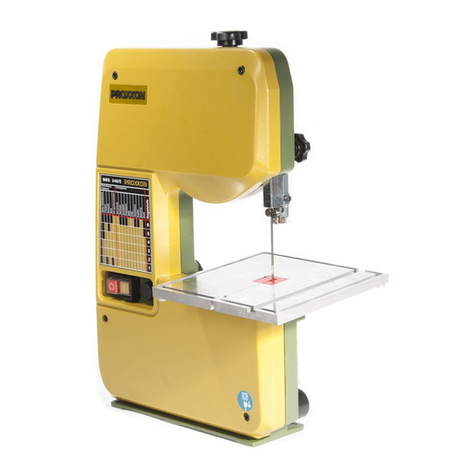
Proxxon MBS/E User manual

ProxxonTools.com
Manual
MBS/E

- 2 -
Fig. 2 Fig. 3
Fig. 1

- 3 -
Fig. 4Fig. 5Fig. 6
Fig. 7 Fig. 8Fig. 9a
Fig. 9bFig. 10aFig. 10b

-4-
Fig. 11 Fig. 12Fig. 13
Fig. 14 Fig. 15 Fig. 16
Fig. 17Fig. 18
Fig. 19
Fig. 20

Dear Customer,
By purchasing your PROXXON MICRO Band Saw
MBS/E, you havechosen agood-quality,high-grade
machine.
In order to operate the MICRO Band Saw safely and
correctly,please read the enclosed safety information
and operating instructions prior to operation.
1. General safety instructions………………………5
2.Additional safety regulations……………………6
3.Additional safety instructions for band saws …6
4. Grounding Instructions…………………………7
5. Description of machine …………………………7
5.1. Legend (Fig. 1) ……………………………………7
5.2.Introduction ………………………………………7
5.3.Specifications……………………………………8
5.4. Scope of supply…………………………………8
6.Machine set-up……………………………………8
6.1. Attaching the work table to the saw……………8
6.2.Checking and verticaladjusting of the upper
blade guide assembly……………………………8
6.2.1. Verticaladjusting of the upper blade guide……8
6.2.2.Checking and adjusting the blade width………8
6.2.3.Using a vacuumcleaner…………………………8
6.2.4. Adjusting tension of the saw blade ……………9
7.Operating the MICRO Band Saw………………9
7.1. Starting operation…………………………………9
7.1.1. Lockable Switch…………………………………9
7.2.Adjusting blade speed……………………………9
7.3.Sawing ……………………………………………9
7.3.1. Free-hand sawing…………………………………9
7.3.2.Sawing with miter guide …………………………9
7.3.3.Operation with the diamond saw blade………10
8. Careand Maintenance…………………………10
8.1. Checking and adjusting lower blade guide …10
8.2.Changing the saw blade ………………………10
8.3.Changing the rubber rings on the wheels……11
8.4. Careand cleaning of the machine ……………11
9. OptionalAccessories……………………………11
10.Accessory Blades………………………………11
This instruction manualcovers:
• safety regulations
•operation and maintenance
• spare parts list
Please readcarefully!
Using this instruction manual will
•make it easier for youto get used to the machine,
•help preventfaults occurring due to improper useand
•increasethe service life of your machine.
Keep this instruction manualinan easily accessible
place. Only operate this machine if you are qualified to
do soand follow the guidelines in this instruction
manual.
Readand become familiar with this entire instruction
manual,learn the tool`s applications,limitations and
possible hazards.
PROXXON does not accept responsibility for the safe
functioning of the machine,
•if it is handled in amanner whichconstitutes
improper use;
•if it is used for other purposes it is not intended and
designed for;
•if it is used for other purposes whichare not speci-
fied in the instruction manual;
•if the safety regulations are not observed.
•Warranty claims are invalid,if the machine is incor-
rectly operated,or the machine has not been suffi-
ciently maintained.
In the interests of your safety,pleasealways observe
the safety regulations.Failure to follow the instructions
listed below,may result in electric shock,fire, and/or
serious personal injury or property damage. This can
result in serious injury or possibly even death.
Only use genuine PROXXON spare parts.
We reserve the right to make further alterations for the
purpose of technical progress.
We wish you every success with your machine.
Readand understand the entire owners manual
beforeattempting assembly or operation!
1. General safety instructions
1. KEEP GUARDS IN PLACE and in working order.
2.REMOVE ADJUSTING KEYS AND WRENCHES.
Form habit of checking to see that keys and
adjusting wrenches are removed from tool before
turning it on.
3.KEEP WORK AREA CLEAN.Cluttered areas and
benches inviteaccidents.
4. DON'T USE IN DANGEROUS ENVIRONMENT.
Don't use power tools in damp or wet locations,or
expose them to rain. Keep workarea well lighted.
5. KEEP CHILDREN AWAY.All visitors should be kept
safe distance from workarea.
6.MAKE WORKSHOP KID PROOF with padlocks,
master switches,or by removing starter keys.
7.DON'T FORCE TOOL.It will do the job better and
safer at the rate for which it was designed.
8. USE RIGHT TOOL.Don't force tool or attachment
todoajobfor which it was not designed.
9. USE PROPER EXTENSION CORD.Make sure your
extension cord is in good condition. When using an
extension cord, be sure to use one heavy enough
tocarry the current your product will draw.An
undersized cord will causeadrop in line voltage
resulting in loss of power and overheating. Table 1
shows the correct size to use depending on cord
lengthand nameplateampere rating. If in doubt,
use the next heavier gage. The smaller the gage
number, the heavier the cord.
Exception No. 1: The reference to the table and the
table itself may be omitted if a statement indicating
the appropriate gage and length is incorporated
into the instruction.
Exception No. 2: The information regarding exten-
sion cords need not be provided for apermanently
connected tool.
10.WEAR PROPER APPAREL.Do not wear loose
clothing,gloves,neckties, rings, bracelets,or other
-5-
jewelry which may get caught in moving parts.
Non-slip footwear is recommended.
Wear protective hair covering tocontain long hair.
Exception: The reference to gloves may be omitted
from the instructions for agrinder.
11. ALWAYS USE SAFETY GLASSES.Also use face or
dust mask if cutting operation is dusty.Everyday
eyeglasses only have impact resistant lenses, they
areNOT safety glasses.
12.SECURE WORK.Useclamps or a vise to hold
work when practical. It's safer than using your
hand and it frees both hands to operate tool.
13.DON'T OVERREACH.Keep proper footing and bal-
anceat all times.
14. MAINTAIN TOOLS WITH CARE.Keep tools sharp
and clean for best and safest performance. Follow
instructions for lubricating and changing acces-
sories.
15. DISCONNECT TOOLS before servicing; when
changing accessories, suchas blades, bits, cut-
ters, and the like.
16.REDUCE THE RISK OF UNINTENTIONAL START-
ING.Make sure switch is in off position before
plugging in.
17.USE RECOMMENDED ACCESSORIES.Consult
the owner's manual for recommended accessories.
The use of improper accessories may cause risk of
injury to persons.
18. NEVER STAND ON TOOL.Serious injury could
occur,if the tool is tipped or if the cutting tool is
unintentionally contacted.
19. CHECK DAMAGED PARTS.Before further use of
the tool, a guard or other part that is damaged
should becarefully checked to determine that it
will operate properly and perform its intended
function check for alignment of moving parts, bind-
ing of moving parts, breakage of parts,mounting,
and any other conditions that may affect its opera-
tion. Aguard or other part that is damaged should
be properly repaired or replaced.
20.DIRECTION OF FEED.Feed work intoa blade or
cutter against the direction of rotation of the blade
or cutter only.
21. NEVER LEAVE TOOL RUNNING UNATTENDED.
TURN POWER OFF.Don't leave tool until it comes
toa complete stop.
Table 1:
Minimum gage for cord:
Total length of
cord in feet25 ft50 ft100 ft150 ft
AWG: 18 161614
2.Additional safety regulations
1. DO NOT OPERATE THIS MACHINE UNTIL it is as-
sembled and installed according to the instruc-
tions.
2.DO NOT OPERATE this machine while tired or
under the influence of drugs, alcohol or any med-
ication.
3.OBTAIN ADVICE from a supervisor,instructor,or
another qualified person if you are not familiar with
the operation of this tool.
4. FOLLOW ALL WIRING CODES and recommended
electricalconnections.
5. ALWAYS USE PROPER BLADE SIZE and type.
6.ADJUST THE UPPER BLADE GUIDE so that it is
as closeas possible to the work piece.
7.KEEP ARMS, HANDS, AND FINGERS away from
the blade.
8. NEVER START THE MACHINE beforeclearing the
table of all objects (tools, scrap pieces,etc.).
9. NEVER START THE MACHINE with the workpiece
against the blade.
10.DO NOT attempt to saw a work piece that does
not haveaflat surfaceagainst the table.
11. HOLD WORKPIECE FIRMLY and feed intoblade at
amoderate speed.
12.TURN THE MACHINE “OFF” toback out of an
uncompleted or jammed cut.
13.MAKE “RELIEF”CUTS prior tocutting long curves.
14. TURN THE MACHINE “OFF”and wait for the blade
to stop prior tocleaning the blade area, removing
debris near the blade, removing or securing work
piece,or changing the angle of the table. A coast-
ing blade canbe dangerous.
15. NEVER PERFORM LAYOUT, ASSEMBLY, or setup
work on the table/workarea when the machine is
running.
16.TURN THE MACHINE “OFF”AND DISCONNECT
THE MACHINE from the power sourcebefore
installing or removing accessories, beforeadjusting
or changing set-ups,or when making repairs.
17.TURN THE MACHINE “OFF”,disconnect the
machine from the power source, and clean the
table/workarea before leaving the machine.
3.Additional safety instructions for
band saws:
For Your OwnSafety ReadInstruction Manual
BeforeOperating MICRO Band Saw.
a)Wear eye protection. Use safety glasses.Please
note: Everyday eyeglasses areNOT safety glasses.
Eye protection equipment should comply with
ANSI Z87.1 standards.
b)During extended periods of operation wear ear
protectors (plugs or muffs).
c)Do not remove jammed cut off pieces until blade
has stopped.
d) Maintain proper adjustment of blade tension, blade
guides, and thrust bearings.Poorly maintained
tools and machines can further damage the tool or
machine and/or cause injury.
e) Adjust upper blade guide so that it is about 1/8"
above the workpiece.
f) Hold workpiece firmly against table.
- 6 -

W arning:
Some dust created by power sanding, sawing,grind-
ing,drilling, and other construction activities contains
chemicals known to the State of California tocause
cancer, birth defects or other reproductive harm. Some
examples of thesechemicals are:
•lead from lead-based paints,
• crystalline silica from bricks and cement and other
masonry products, and
•
arsenic and chromium from chemically-treated lumber.
Your risk from these exposures varies,depending on
how often you do this type of work. To reduce your
exposure to thesechemicals: workina well ventilated
area, and work withapproved safety equipment, such
as those dust masks that are specially designed to fil-
ter out microscopicparticles.
Usea vacuumcleaner for wood dust collection as
described in our manual whenever possible.
4. Grounding Instructions
In the event of amalfunction or breakdown,grounding
provides apath of least resistance for electric current
to reduce the risk of electric shock. This tool is
equipped withan electric cord having an equipment-
grounding conductor and agrounding plug. The plug
must be plugged intoamatching outlet that is proper-
ly installed and grounded in accordance withall local
codes and ordinances.
Do not modify the plug provided – if it will not fit the
outlet,have the proper outlet installed by aqualified
electrician.
Improper connection of the equipment-grounding con-
ductor can result in a risk of electric shock. The con-
ductor with insulation having an outer surface that is
green with or without yellow stripes is the equipment-
grounding conductor.If repair or replacement of the
electric cord or plug is necessary,do not connect the
equipment-grounding conductor toalive terminal.
Check withaqualified electrician or service personnel,
if the grounding instructions are not completely under-
stood,or if in doubt as to whether the tool is properly
grounded. Use only 3-wire extension cords that have
3-prong grounding plugs and 3-pole receptacles that
accept the tool’s plug.
Repair or replace damaged or worncord immediately.
This tool is intended for useona circuit that has an
outlet that looks like the one illustrated in SketchAin
Figure 21.
The tool has agrounding plug that looks like the plug
illustrated in SketchAin Figure 21. A temporary
adapter, which looks like the adapter illustrated in
Sketches B and C, may be used toconnect this plug
toa 2-pole receptacle as showninSketchBif aprop-
erly grounded outlet is not available. The temporary
adapter should be used only until aproperly grounded
outlet canbe installed by aqualified electrician. The
green-colored rigid ear,lug, and the like,extending
from the adapter must beconnected toapermanent
ground suchas aproperly grounded outlet box.
5. Description of machine
5.1. Legend (Fig. 1)
1Cover for housing 9Saw blade
2Fastening screw10Working table
3Housing 11 Socket
4Adjustment screw12Machine base
5Clamping screw13Control knob
6Guide rod 14 On-Off switch
7Saw blade cover15 Diagram
8Saw blade guide 16Push-Stick
5.2.Introduction
The MICRO Band Saw MBS/E cuts steel,non-ferrous
materials, wood and plasticmaterials and canalsobe
used for glass and ceramics when fitted withadia-
mond saw blade. The MBS/Eis driven by apowerful
115 Vmotor with electronic speed regulation for the
adjustment of the correct band speed for excellent
working results.The low noise motor (high quality,for
quiet,prolonged use) operates via toothed belt.
A solid, ribbed die-cast aluminum housing (not a tubu-
lar or sheet metalconstruction) ensures the necessary
stability.The machine has double ball bearing alu-
minum pulleys, a sturdy machined table witha slot for
the miter gauge as well as the coolant trough.
The possibility of adjusting the work table toany angle
between 0°and 45° ensures cleanand accurate miter
cuts.
Electronically controlled speeds for exceptionally
accuratecutting (no subsequent finishing necessary)
areavailable from 395 to 820 ft/min. Apractical table
at the outside of the machine housing indicates the
recommended speed for various types of material.
The machine comes equipped with one 42" x 13 / 64" x
1 / 64 " (1065 x 0,5 x 0,4 mm) band saw blade (14 TPI).
The blade section size13 / 64 " x 1 / 64" (5 x 0.4 mm) is
ideal for fine work, allowing tocut even smallest radii
(alsoavailable as accessory, NO 28 176) .
The scope of delivery includes amiter guide with gra-
dation and twoAllen keys as well as apush stick. The
MICRO Band Saw canbe equipped withan optionally
available liquid coolant system.
- 7 -
GROUNDING
ADAPTER
GROUNDING GROUNDING
MEANS
METAL SCREW
COVER OF GROUNDED
OUTLET BOX
<A><B>
<C>
<D>
PIN
PIN
Figure 21:

The machine is also equipped witha vacuum-cleaner
adapter to help you work in adust-free environment.
We recommend only to use originalPROXXON spare
parts and saw blades.
5.3.Specifications
Nominal voltage:110-120V AC, 60 Hz
Power:1 / 8hp (85 Watts)
Band speed:395 to 820 ft/min,infinitely
variable
Noise level:<70 dB(A)
Weight:15.5 lb(7 kg)
Dimensions:
Work table:7 7 / 8 " x 7 21 / 32" (adjustable
from 0 to 45°)
Throat depth5
29 / 32" (max. 150 mm)
Max.Work piece height:2 5 / 32” (max. 55 mm)
Length of saw blade:42"
5.4. Scope of supply
1pc.Band Saw
1pc.Work table
(with knob and sleeve)
1pc.Rubber socket
1pc.Miter gauge
1pc.Push-stick
4pc.Allen keys
1pc.Manual
Fixing screws
Packaging
6.Machine set-up
W arning!
Toavoid injury from unexpected starting or electrical
shock,do not plug the power cord intoapower
source receptacle during unpacking and assembly.
Never connect the plug to the power source recepta-
cle until the assembly and adjustment steps arecom-
pleted, and you have readand understood the safety
and operating instructions.Make certain the switch is
in the off position beforeconnecting the machine to
the power source receptacle.
1Unpack the MICRO Band Saw and check for com-
pleteness.
Note:
For safety reasons the machine should be fastened
with the 3 wood screws (included) toa strong work
bench (see fig. 2). Make sure the MICRO Band Saw is
firmly secured to the benchbefore useand keep the
floor around the machine cleanand free of scrap
material,oil and grease.
6.1. Attaching the work table to the saw
1. Unscrew the brass screw 1 from the sawing gap
(fig. 3) in the working table.
2.Slide the working table 3 (fig. 4) into the respective
recess and fasten it with the knob 2 and the
sleeve1.Set the mark to ”0”.
3.Screw the brass screw 1 (fig. 3)back in.
6.2.Checking and verticaladjusting of the upper
blade guide assembly
W arning:
Disconnect the machine from the power source!
Properly adjust the blade guides before use!
6.2.1. Verticaladjusting of the upper blade guide
For excellent working results please set the upper
blade guide assembly as closeas possible to the top
surface of the work piece.
1. Loosen the knob1 (fig. 9a)and move the guide
assembly 2 into the desired position.
2.Tighten the knob1.
6.2.2.Checking and adjusting the blade width
W arning:
Disconnect the machine from the power source!
Properly adjust the blade guides before use!
Adjust the upper saw blade guide 1 (fig.5) to the width
of the respective saw blade. The edge Amust thereby
be in line with line ”5” on the scale (e.g. saw blade
1065 _ ”5” _ 0.4). The band must now touch the rear
roller.
1. Slightly loosen the socket headcap screws withan
Allen key 3 (fig. 5).
2.Slide the adjusting piece (2) until it matches line
”5” on the scale.
3.Tighten the socket headcap screw (3,included),
but not too tight!
4. The saw blade thickness canbecorrected by
means of the set-screw 4.
6.2.3.Using a vacuumcleaner
Note:
When cutting wood or plasticmaterials the machine
should beconnected toadust extractor (vacuum
cleaner) toavoid accumulation of saw chips inside the
machine.
1. Connect the vacuumcleaner to the rubber socket
1 (fig. 6).
Please first make sure that the plate1(see fig. 7) is
inserted. This is necessary when often sawing wood or
similar materials.
When often cutting aluminum,metal,glass, tiles etc.
remove this plate toavoid accumulation of chips
inside the machine.
2.Unscrew four socket headcap screws 2 from the
housing 1 (fig. 1) and take the cover off.
3.Slide the plate 1 (fig. 7) in and connect the vacuum
cleaner to the socket 1 (fig. 6).
4. Install the housing cover.
-8-

6.2.4. Adjusting tension of the saw blade
W arning!
Always disconnect the machine from the power source
while adjusting the blade tension!
Properly adjust the blade tension before use!
The saw blade is tensioned correctly when it runs
quietly and without vibrations.The saw blade also
must not run sideways off the wheels.
The band saw is equipped by aknob toadjust the
blade tension correctly.Proceed as follows:
1. Loosen the knob 2 (fig. 8) in direction A
2.Turn the knob(1) in direction (A) to tension or in
direction (B) to loosen the saw blade.
3.Tighten knob(2).
Caution!
An extremely tensioned saw blade may breakand
damage the machine! Over-straining alsocauses poor
performance!
7.Operating the MICRO Band Saw
W arning!
-Toavoid injury from accidental start,make sure the
switch is in the OFF position and the plug is not
connected to the power source receptacle before
changing any parts.
-Please read the following safety regulations thor-
oughly and follow them before starting work with
the machine.
-Safe and precision working practicecan only be
ensured with the unit properly secured!
-Do not leave the unit switched on,it unsupervised.
-Use only saw blades in good condition!
-Replaceblunt and deformed saw blades immedi-
ately!
-Always disconnect the machine from the mains
supply for cleaning and service work!
-Do not run the machine unattended!
Note:
-Fasten the work piece securely.When sawing
round work pieces useanappropriate device to
secure the work pieceagainst turning.
-Use the push stick when working close to the saw
blade.
7.1. Starting operation
Attention!
Before starting the band saw should beconnected to
adust extracting device.
Remove loose items and unnecessary work pieces
from the area before starting the machine
1. Connect the machine to the mains supply.
2.Switch the machine on with the power switch 4
(fig. 9 a)
7.1.1. Lockable Switch
Your MICRO Band Saw is equipped withalockable
switch (fig. 9 b): It allows you to make the saw child-
proof and makes any other unauthorized use impracti-
calas well. With the pulled-out pin like shown in the
sketch you cannot switch on the machine. Soanacci-
dental start-up will be impossible and unauthorized
use is prevented.
Anaccidental start-up of the machine by a child or
visitor could cause injury!
To save the machine, set the switch in position “Off”,
pull out the pin and disconnect the machine from the
power source.
To start the machine again and to operate the switch
in the usual way,just push the pin back into its open-
ing. Then you can reconnect the machine to the power
sourceand work with it.
7.2.Adjusting blade speed
Before starting work, adjust the appropriate speed for
the saw blade and the material.
Vernier adjustment of the band speed is possible with
the speed regulator 3 (fig. 9 a). Refer to the diagram
(5) for optimalband speed. The values are,however,
only reference values!
Generally applicable:
High band speed for thin materialand low band speed
for thick material.
7.3.Sawing
Mark the cut on the work piece. Never brake the band
speed by pushing too hard. The saw blade must ”cut
freely”, so the best results will beachieved. Incase of
vibrations adapt the band speed respectively.
7.3.1. Free-hand sawing
Press the work piece onto the work table,guide it
carefully and only with little force (fig.10 a). More
pressureagainst the work table,less pressureagainst
the saw blade.
Always avoid awkward operations and hand positions
wherea sudden slip could causeahand to move into
the blade. In thesecases use the push-stick (provided
with the saw, see fig. 10 b).
7.3.2.Sawing with miter guide
Attention!
Adjustments must only becarried out with the
machine switched off.
1. Adjust the desired angle on the miter guide.
2.Press the work piece lightly against the saw blade
(fig. 11).
7.3.2.1. Miter cuts
For miter cuts the working table canbe tilted toany
angle between 0°and 45°.
-9-

1. Loosen the clamping screw 1 (fig. 12)and tilt the
table to the desired angle.
2.Read the degrees on the scale (2).
3.Tighten the clamping screw (1).
7.3.3.Operation with the diamond saw blade:
For stones, ceramics,glass and fiberglass (42" x 7 / 64"
x 1 / 64 "). Adiamond saw band must only be used in
combination witha correctly mounted liquid coolant
system. Aliquid coolant kit is available by PROXXON
as anaccessory, see also fig. 13.Don´t work with the
diamond saw blade without appropriatecooling.
Note:
For operation withaliquid coolant system we recom-
mend the installation of a Coolant collection tray 3 (fig.
13). This Coolant collection tray is available as an
accessory by PROXXON.To seal the screwing holes
put the band saw on a rubber plateand fasten it with
the wood screws.
Attention!
To install the liquid cooling system follow the enclosed
instructions exactly!
7.3.3.1. Notes on the coolant:
When working withcoolant: Use only commercially
available,mineral or synthetic, water soluble coolants.
Concentration: 2 - 5%,depending on material.
Dispose of liquids after workaccording to instructions
from the manufacturer.
1. Switch the machine on.
2.Open the shut-off valve 1 (fig. 14) and adjust the
flow.Use enough coolant.
7.3.3.2.Working withadiamond saw blade
Caution!
Cutting of radii smaller than 15 mm is not possible
with the diamond saw band (fig. 15).
Do not use diamond saw blades for metal,plastic
materials or wood!
Note:
Only sufficient cooling of the diamond saw blade
ensures better and quicker cutting of glass and ceram-
ics and prolongs the lifetime of the diamond band.
1. Guide the work piececarefully and only with little
force.
2.Close the shut-off valve 1 (fig. 14) after finishing
work or during breaks.
8. Careand Maintenance:
8.1. Checking and adjusting lower blade guide
Warning: Disconnect the machine from the power source!
The machine is fitted witha saw blade
42“ x 13/64“ x 1/64“ from the factory.
5. Unscrew four socket headcap screws from the
housing 2 (fig. 1) and take the cover 1 off.
6.Check the fit of the saw blade in the lower band
guide 1 (fig. 16). The guide slot must be exactly
vertical.
7.Adjust the band guide (only if necessary!) after
loosening the clamping screw 2.
8. Tighten screw 2 and reinstall housing cover..
8.2.Changing the saw blade
Caution!
-Use only spare parts recommended for this MICRO
Band Saw.Follow the instructions that accompany
accessories.Use of improper spare parts may
cause hazards.
-Always pull the mains plug out when changing parts.
-Blade teethare sharp! Usecare when handling the
saw blade. Failure tocomply may cause serious
injury.
1. Unscrew four socket headcap screws 2 (fig. 17)
and take the housing cover 1 off.
2.Unscrew the brass screw 1 (fig. 18).
3.Loosen the clamping screw 3 (fig. 17) for half a turn.
4. Turn the knob4 until the saw blade canbe
removed from the wheels 2 and 3 (fig. 18).
5. Insert the new saw blade into the sawing gap with
the non-toothed side forwardand the teeth point-
ing downwards (towards the sawing table).
Note:
There is apossibility that the saw blade has ”turned
over”.
In sucha case make sure to turn the saw blade back.
The teeth must point to the front and downwards.
When changing toa wider or narrower saw blade the
saw blade guide must beadjusted accordingly (see
”Checking and adjusting the blade width ”).
6.After changing the blade you always should check
tension of the saw band. See 6.2.4.
7.Turn the knob4 (fig. 17) until the saw blade is light-
ly tensioned.
8. Tighten the clamping screw 3 (fig. 17)and reinstall
the brass screw 1 (fig. 18).
Caution!
Extreme tensioning cancause damage to the machine
and breaking of the saw blade.
9. Install the housing cover 1 (fig. 17)and fasten the
socket headcap screws 2.
Note:
The saw blade must not run sideways off the wheels.
You find further instructions in the chapter "6.2.4.
Adjusting tension of the saw blade" on page 9.
- 10-

8.3.Changing the rubber rings on the wheels
Each wheel is covered witha rubber ring to protect
the saw blade. These rubber rings are wear items and
must be replaced whenever necessary.The rubber
rings must thereforebe examined regularly.Incase of
a‘hollow shape’ caused by abrasion (fig. 19), the
respective ring must be replaced immediately.
1. Cut the worn rubber ring (fig. 20)by using a sharp,
heated knife.
2.Warm up the new rubber ring for 10 minutes in hot
water (not boiling).
3.Press the plastic ring firmly onto the wheel, until it
sits perfectly in the groove.
Install the wheel and the housing cover and fasten it
with the 4 socket headcap screws.
8.4. Careand cleaning of the machine
W arning!
Always disconnect the mains plug prior tocleaning
and maintenance operations.
Ifany part is missing or damaged,do not plug the
MICRO Band Saw in until the missing or damaged
part is replaced, and assembly is complete. Toavoid
electrical shock, use only identical replacement parts
when servicing double insulated tools.
Toavoid fire or toxic reaction,never use gasoline,
naphtha, acetone,lacquer thinner,or similar highly
volatile solvents toclean the MICRO Band Saw.
Do not allow brake fluids,gasoline,or penetrating oils
tocome in contact with the plasticparts.They contain
chemicals that can damage or destroy plastics.
Turn switchOFF and always remove plug from power
sourcebefore making any adjustments or repairs.
All electrical or mechanical repairs should be done
only by qualified service technicians.
When servicing use only PROXXON replacement
parts.Use of any other parts may createahazard or
cause product damage.
Any attempt to repair or replace electrical parts on this
MICRO Band Saw may createahazard unless repair
is done by aqualified service technician. Repair serv-
ice is available at your PROXXON servicecenter (You
find the address on the back of this manual)
•After working with the machine removeall chips
witha suitable hand broom, a vacuumcleaner, a
brush or compressed air— do not use your hands.
Turn off the machine beforecleaning.
•Clean the machine regularly witha cloth from all dirt.
9. OptionalAccessories
Note:
Useaccessories and spare parts that havebeen rec-
ommended by PROXXON.Improper accessories may
be hazardous!
NO 28 187Blade guide
Triple ball bearing system with feed pipe
for coolant when used with the diamond
blade. Canalsobe used in conjunction
with normalblades.
Liquid coolant kit for MBS/E:
For wet cutting and finishing of glass, stones and tiles.
NO 28 188 Coolant container:
Plastic container with stopcock, 39" (100 cm)
tubing, 2 nipples for the MBS/E table and
mounting bracket/screws.Holds 1 quart.
NO 28 189 Coolant collection tray
Size 16 17 / 32" x 12 13/ 64" x 19/ 32"
(420 x 310 x 15 mm). Includes gasket for
sealing the attachment holes of the
machine. With 19 11/ 16" (50 cm) discharge
tubeand nipple for band saw table. The
tray is undrilled and may sobe used on
other machines, too.
10.Accessory Blades
NO 28 174Swedish steel 42" x 13/ 64" x 1 / 64 " (1,065 x
5 x 0.4 mm). Fine toothed (24TPI). For
steel and brass.
NO 28 176 Swedish steel, same size, but coarse
toothed (14 TPI). For wood and plastics.
NO 28 180Special tempered Swedish steel with
induction-hardened teeth. Extranarrow for
tight curves 42" x 9 / 64" x 1 / 64" (1,065 x 3.5
x 0.5 mm). Coarse toothed (14 TPI). For
aluminumand plastic.
NO 28 186Diamond blade
For stones, ceramics,glass and fiberglass.
42" x 7 / 64 " x 1 / 64 " (1,065 x 3 x 0.3 mm).
The cutting of glass and ceramics should
only beattempted in conjunction with the
optionally available coolant system. See
for details above (Point 9)!
- 11 -
Table of contents
Other Proxxon Saw manuals

Proxxon
Proxxon KS 230 User manual

Proxxon
Proxxon FET User manual

Proxxon
Proxxon KGS 80 User manual

Proxxon
Proxxon DSH User manual

Proxxon
Proxxon DSH Quick guide

Proxxon
Proxxon FET User manual

Proxxon
Proxxon FET User manual

Proxxon
Proxxon FET User manual

Proxxon
Proxxon MICRO User manual

Proxxon
Proxxon KT 70 User manual

Proxxon
Proxxon KGS 80 User manual

Proxxon
Proxxon KGS 80 User manual

Proxxon
Proxxon DSH/E User manual

Proxxon
Proxxon DS 230E User manual

Proxxon
Proxxon DSH User manual

Proxxon
Proxxon FET User manual

Proxxon
Proxxon MBS 240 / E User manual

Proxxon
Proxxon KG 50 User manual

Proxxon
Proxxon MBS 240/E User manual

Proxxon
Proxxon Micromot 230/E User manual