Proxxon DS 460 User manual

DS 460
Manual

4
1
17
18
6
21
7
19
3
11
10
11
2
20
8
1322
23
14153
16
12
3
14
15
22
13
26 27 5428
23
22
9
24
8
25
15
0
30
45
4
1
2
3
o
5
5
5
2
4
3
1
1
3
2
2
1
3
Fig. 1a
Fig. 3
Fig. 6
Fig. 4
Fig. 5
Fig. 1b
Fig. 2a Fig. 2b
10
11

+-
1
Fig. 9
2
6
7
5
1
3
3
2
1
54
1
3
4
5
2
Fig. 10
Fig. 11
Fig. 7b
Fig. 7a
1
4
5
7
2
3
6
Fig. 8
7
6
4
3
2
1
1
7
5
6
Fig. 12a Fig. 12b

Translation of the Original Operating
Instructions
Contents:
1Scroll Saw DS 460: ……………………………………………12
2General Safety Information ……………………………………12
3Legend (Fig. 1) …………………………………………………13
4Description of the Machine (see also fig. 1a and 1b) ………13
5Technical Data: …………………………………………………13
6Installation and Commissioning of the Saw …………………14
6.1 Unpacking (Fig. 2a and 2b): …………………………………14
6.2 Installing the Saw ………………………………………………14
6.3 Adjusting the Angle Display (Fig. 3): …………………………14
6.4 Assembling the Air Nozzle (Fig. 4): …………………………14
6.5 Connecting the Vacuum Cleaner (Fig. 5):……………………14
6.6 Saw Blades……………………………………………………14
6.6.1 Clamping and Changing the Saw Blade ……………………14
6.6.1.1 Pushing the Saw Table Back or into the
Working Position (Fig. 6) ………………………………………14
6.6.1.2 Saw Blades with Flat Ends
(Hand and Fret Saw Blades) (Fig. 7a and 7b): ……………15
6.6.2 Swa Blades with Pin Ends (Fig. 8): …………………………15
6.6.3 Fine Setting of the Correct Saw Tension (Fig. 9): …………15
7Working with the Saw: …………………………………………15
7.1 General Information for Working with the Scroll Saw ………15
7.1.1 Choice of Saw Blade …………………………………………15
7.1.2 Selecting the Speed:…………………………………………16
7.1.3 Possible Causes of Broken Saw Blades: ……………………16
7.2 Sawing (Fig. 10) ………………………………………………16
7.2.1 Inside Cuts (Fig. 11) ……………………………………………16
7.2.2 Mitre Cuts (Fig. 2b) ……………………………………………16
7.2.2.1 Setting the Mitre Angle…………………………………………16
7.2.2.2 Fine Setting (Fig. 2b) …………………………………………16
7.2.2.3 Setting the saw blade stroke (fig. 12 a and 12 b) …………16
8Maintenance and Repairs ……………………………………17
9Cleaning and Care: ……………………………………………17
10 Disposal …………………………………………………………17
11 CE Declaration: …………………………………………………17
12 Spare Parts List…………………………………………………78
13 Exploded Drawing………………………………………………79
1Scroll Saw DS 460:
Dear customer!
The use of these instructions
•makes it easier to become acquainted with the device,
•prevents malfunctions due to improper handling, and
•increases the service life of your device.
Always keep these instructions close to hand.
Only operate this device with exact knowledge of it and comply with the
instructions.
PROXXON will not be liable for the safe function of the device for:
•handling that does not comply with the usual intended use,
•other application uses that are not stated in the instructions,
•disregard of the safety regulations,
You will not have any warranty claims for:
•operating errors,
•lack of maintenance.
For your safety, please comply with the safety regulations without fail.
Only use original PROXXON spare parts.
All rights reserved for further developments in the course of technical
progress. We wish you much success with the device.
2General Safety Information
CAUTION! When using electric power tools, the following safety
measures must be observed for protection from electric shock,
risk of injury, and fire hazards.
Read and take note of all these instructions before you start up
the product. Keep these safety instructions in a safe place.
Safe working
Always keep your working area tidy.
1. Disorder in the working area can lead to accidents.
Take account of surrounding influences.
1. Do not expose tools to the rain.
2. Do not use tools in damp or wet surroundings.
3. Ensure that the lighting is good.
4. Do not use tools in the vicinity of combustible liquids or gases.
Protect yourself from electric shocks.
1. Avoid body parts from coming into contact with earthed parts.
Keep other people away.
1. Do not let other people, especially children, touch the tool or the
cable. Keep them well away from the working area.
Keep unused tools in a safe place.
1. Unused equipment should be kept in a dry, closed location out of
the reach of children.
Do not overload your tool.
1. You will be able to work better and safer within the given power
range.
Always use the correct tool.
1. Do not use low power machines for heavy work.
2. Do not use tools for purposes for which they were not designed. For
example do not use manually-operated circular saws for cutting
branches or firewood.
Wear suitable working clothing.
1. Do not wear loose clothing or jewellery, they can get caught up by
moving parts.
2. When working in the open air we recommend the use of non-slip
footwear.
3. Wear a hair net if you have long hair.
Use the protective equipment.
1. Wear safety glasses.
2. Wear a breathing mask when carrying out dust-generating work.
Connect to the dust extraction equipment.
1. If connections are available to dust extraction and collection equip-
ment, make sure that they are properly connected and used.
Do not use the cable for purposes for which it was not designed.
1. Do not use the cable to pull the plug out of its socket. Protect the
cable from heat, oil and sharp edges.
Secure the tool.
1. Use the clamping fixture or a vice to hold the tool tightly. It is thus
held more safely than with your hand.
Avoid abnormal postures.
1. Ensure that you are standing safely and always maintain your bal-
ance.
Take great care of your tools.
1. Keep the tools sharp and clean so as to be able to work better and
safer.
2. Follow the maintenance instructions and the advice about tool
changing.
12
GB

3. Regularly check the tool cable and have it replaced by an author-
ized specialist if it is damaged.
4. Regularly check the extension cables and replace them if they are
damaged.
5. Keep handles dry and free from oil and grease.
Pull the plug out of the socket:
1. When the tool is not in use, before maintenance and when chang-
ing tools such as the saw blade, drill or milling cutters, always take
the plug out of the socket.
Do not leave any tool spanners or setting keys in place.
1. Before switching on always check that spanners, keys and setting
tools have been removed.
Avoid unintentional starting.
1. Always make sure that the switch is in the OFF position when you
plug the tool into the socket.
Extension cables in the open air.
1. In the open air always use extension cables which are authorized
for the purpose and which are correspondingly marked.
Always be attentive.
1. Be aware of what you are doing. Carry out your work sensibly. Do
not use the tool if you are tired.
Check the tool for damage.
1. Before further use of the tool, examine protective devices or
slightly-damaged parts to ensure that the function is perfect and
meets the requirements.
2. Check that the moving parts function perfectly and do not stick and
that parts are not damaged. All parts must be correctly mounted
and all the conditions fulfilled to ensure trouble-free tool operation.
3. Damaged protective equipment and parts must be properly repaired
or exchanged by an authorized specialist workshop if no other infor-
mation is given in the instructions for use.
4. Arrange for damaged switches to be exchanged by a customer
services workshop.
5. Never use tools on which the switch cannot be switched on and off.
WARNING!
1. The use of other tool inserts and accessories can present a risk of
injury.
Arrange for your tool to be repaired by a specialist electrician
1. This tool meets the relevant safety regulations. Repairs may only be
carried out by electrical specialists and original spare parts must be
used. Otherwise accidents can happen to the user.
3Legend (Fig. 1)
1. Adjusting knob for saw blade tension
2. Saw blade holder, top
3. Saw blade
4. ON - OFF switch
5. Adjusting knob for number of strokes
6. Screw for fine setting of the work table’s angle of rotation
7. Die-cast steel pedestal
8. Air nozzle
9. Die-cast steel machine body
10. Rotatable saw table
11. Saw blade holder, bottom
12. Holes for fastening screws
13. Slide blocks for clamping the saw blade
14. Rubber connecting piece for vacuum cleaner connection
15. Mains cable
16. Induction motor
17. Saw arm (top)
18. Saw arm (bottom)
19. Recesses for the slide blocks
20. Lock lever
21. Clamping screw for lock lever
22. T-handle key
23. Hose
24. Clamping screw for air nozzle alignment
25. Dust suction connection
26. Arm for saw blade guard
27. Clamping screw for saw blade guard
28. Saw blade guard
4Description of the Machine
(see also fig. 1a and 1b)
The PROXXON scroll saw is a very sturdy, ruggedly designed but nev-
ertheless mechanically very sophisticated and carefully produced
device. The heavy die-cast pedestal and the rigid die-cast machine
body form a solid base for the complex machine mechanics and a per-
fect platform for the precision mounting of the saw arms which are
made of ultra-light but strong magnesium in order to reduce the moved
weights. They are driven by a quiet, powerful induction motor which
can be adapted to the required material properties with two speeds
(900/1400 rpm) for optimum smooth running and low vibration.
Your DS 460 has many areas of application and is particularly suitable
for mould construction, fine mechanics, model building and toy manu-
facture. It is therefore just the right tool for ambitious model builders,
designers, architects (model building) or carpenters.
The large tiltable saw table for mitre cuts of -5 to 50° is made of die-
cast aluminium for maximum accuracy and stability and precision
ground for optimum gliding characteristics. Its special design also sim-
plifies changing of the saw blade.
The saw table can be unlocked and pushed back to improve the acces-
sibility of the lower saw blade attachment. This enables quick and easy
changing of the saw blades.
Saw blades with both pin ends and flat ends can be used. The use of
sliding blocks allows precise guiding of the saw blade without interfer-
ence from bending forces.
You will find the appropriate saw blades for the respective job in the
Proxxon range of accessories. We recommend you to use Proxxon
saw blades exclusively!
The DS 460 saws soft wood up to a thickness of 50 mm, plastic up to
30 mm and non-ferrous metals up to 10 mm.
The saw can also be used to easily cut plexiglass, GRP, foam, rubber,
leather and cork.
And there is an automatically driven bellows with an adjustable air noz-
zle to ensure that dust does not obstruct the view of the cutting line
during work.
A vacuum cleaner can be connected additionally. This guarantees
clean working.
5Technical Data:
Number of strokes:900 or 1,400/min
Lifting height: 18 mm
Max. cutting depth: 60 mm
(in wood) at 45°: 35 mm
Saw blade length: 127 mm (with pin end)
125-130 mm (without pin end)
Noise development: < 70 dB(A)
Vibration < 2.5 m/s
Weight: approx. 20 kg
Dimensions:
LxWxH 580 x 320 x 300 (in mm, approx. data)
Table: 400 x 250 mm
Throat: 460 mm
Motor:
Voltage: 220/240 V, 50/60 Hz
Power input: 145/205 W
13

6Installation and Commissioning of the Saw
Caution:
Make sure your mains plug has a protective earthing conductor and is
suitable to operate the device!
6.1 Unpacking (Fig. 2a and 2b):
1. Take the device carefully out of the box. Please hold the scroll saw
by the die-cast housing as shown in fig. 2a. This will avoid damage.
2. The saw table 1 is folded up at an angle of about 45° for transport
reasons. Please loosen the clamping screw 2 (fig. 2b), pull down
the lock lever of the angle adjustment, move the table into the hori-
zontal position and snap the lock lever back into the gear 4.
6.2 Installing the Saw
N.B.:
Safe and accurate work is only possible with careful fastening!
1. Fix the saw to a strong workbench with two screws (Ø 8 mm, not
included). Use the holes (12, fig. 1) on the right and left in the
pedestal.
6.3 Adjusting the Angle Display (Fig. 3):
Caution:
Make sure that the mains plug is removed before doing any setting
work, otherwise there is a danger of injury in case of accidental starting
of the machine!
The angle display 1 is set exactly at the factory and does not normally
need to be readjusted. If it has become misadjusted, this is quite easy
to correct:
1. Clamp the saw blade 2. See the relevant section of this manual.
2. Set the saw table to the “0°” position. See the section “Mitre Cuts”.
This tells you how to set the angle of the saw table.
3. Check using a square 3 whether the saw blade actually is at a right
angle to the saw table in this position. If not, readjust the saw table
setting at the knurled screw 4.
4. Check the position in the angle display 1. This must now be aligned
exactly to the 0° position on the scale.
5. If the angle display needs to be adjusted, loosen the Allen screw 5,
move the angle display to the 0° position and retighten the Allen
screw.
6. Test by sawing a piece of wood and check the angle on the work-
piece again.
6.4 Assembling the Air Nozzle (Fig. 4):
Sawdust along the cutting line is removed immediately by a blower dur-
ing work. Ideal for a free view. The blower starts automatically as soon
as the saw is switched on.
1. Remove the air nozzle pipe 1 and hose 2 from the enclosed bag.
2. Loosen the knurled screw 3 and insert the air nozzle pipe 1 into the
appropriate recess in the open clamping pieces 4.
3. Align the air nozzle pipe and tighten the knurled screw 3.
4. Push the air hose 2 onto the rear end of the air nozzle pipe 1 and
the nipple 5 on the bellows on the top saw arm.
To align the air nozzle, simply loosen the knurled screw 3 and position
the air nozzle pipe by turning and moving it towards the workpiece.
6.5 Connecting the Vacuum Cleaner (Fig. 5):
Caution:
Saw dust from certain materials can be hazardous to your health if
inhaled or if it touches your skin. For that reason, always wear appro-
priate protective clothing (e.g. respirator) and always work with the suc-
tion device.
Danger: Dust in certain concentrations can generate an explosive
mixture in the air!
1. Push the rubber connector 1 onto the connecting piece 2.
2. Push the vacuum cleaner hose 3 onto the rubber connector 1.
3. Switch on the vacuum cleaner before sawing so that the sawdust is
sucked off and the suction device is not blocked.
Another small tip:
When using the Proxxon CW-matic vacuum cleaner, manual switching
on and off is no longer necessary. The CW-matic is equipped with an
automatic control that switches on and off automatically whenever the
electrical tool is activated or deactivated. You have the same effect
with commercially available vacuum cleaners when using our AS/E
vacuum cleaner controller.
6.6 Saw Blades
Caution:
Always pull out the mains plug for all the activities described here.
Only use suitable saw blades. Make sure that the saw blades are suit-
able for use with the DS 460. You must comply with the dimensions
specified in the technical data.
Please make sure that the saw blade is in perfect condition and
change damaged or worn saw blades immediately! Deformed or dam-
aged saw blades are dangerous to work with and may not be used!
They also produce poor work results: Full sawing performance and
precision can only be achieved with perfect saw blades.
We recommend the use of original PROXXON saw blades!
Choose the suitable saw blades carefully and for the respective appli-
cation and material to be sawn.
Proxxon supplies different fine teeth, flat and round blades and blades
with and without pin ends. You will find our range of blades in the
Micromot catalogue or on the Internet under www.proxxon.com.
6.6.1 Clamping and Changing the Saw Blade
Both conventional saw blades with pin ends and hand (fret) saw blades
without pin ends can be used. The saw table can be pushed back for
optimum accessibility of the saw blade holder so that changing the saw
blades is child’s play.
Caution:
Please note that the saw blade guard can be folded away to change
the saw blades.
6.6.1.1 Pushing the Saw Table Back or into the Working
Position (Fig. 6)
Caution:
Please note that the saw table can only be pushed back when the saw
table is in the 0° position, i.e. horizontal.
1. Release clamping screw 1 (fig. 6) of the lock lever 2.
2. Move down the lock lever and push the saw table 3 back.
3. Pull the saw table 3 forward after attaching the saw blade. The lock
lever is actuated automatically in the front end position and locks
the saw table.
6.6.1.2 Saw Blades with Flat Ends (Hand and Fret Saw
Blades) (Fig. 7a and 7b):
The concept of the DS 460 is not designed like conventional scroll
saws to simply clamp the blades in the saw blade holders at the ends
of the saw arms. This conventional clamping method inevitably leads to
fluctuating bending forces in the saw blade when the saw arms move
up and down because the pendulum movement cannot be compen-
sated. These cause heavy wear, the saw blade can break sooner.
Frequent blade changing is not to everyone’s liking either. We have
designed the clamping method with sliding blocks for all those who do
14

not want to do without the more accurate guiding of the blades with flat
ends (unlike those with pin ends) but do not want their disadvantages.
There is no lateral twisting in the attachment yet the blades can still fol-
low the up and down movements of the saw arms freely without being
exposed to bending forces.
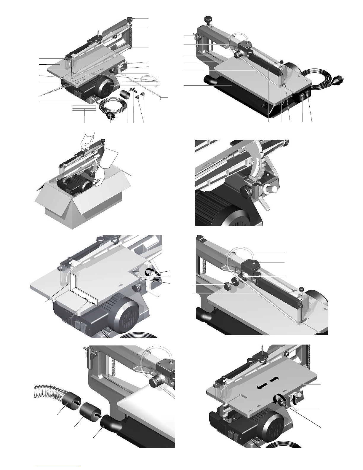
1. Place the sliding blocks 1 (fig. 7a) in the openings provided in the
saw table 2. The right clamping length is defined immediately. Cau-
tion: The clamping nuts 3 must be loosened and facing upwards!
The sliding blocks must be inserted so that the pointed ends are
facing each other, i.e. inwards.
2. Insert the saw blade in the centre of the clamping slit and tighten
the clamping nuts with the Allen key 5 provided. Caution: The saw
blade must be inserted the same distance into the clamping slit on
both sliding blocks.
3. Push back the saw table 2 as described above and fold away the
saw blade guard 6 if necessary.
4. Turn the knob 7 to the left to loosen the tension on the saw blade.
5. Remove the saw blade if necessary and insert a new saw blade 4
with the sliding blocks into the saw blade holders as shown in fig.
7b. Slight pressure can be applied to the top arm as required or the
blade tension can be loosened further on the knob 7 if necessary.
Caution: The teeth of the blade must face downwards!
6. Pull the table forward again as described above.
7. Regulate the saw blade tension as described in the section “Fine
Setting of the Correct Saw Tension”.
6.6.2 Swa Blades with Pin Ends (Fig. 8):
Saw blades with pin ends are very suitable for working with many
closed inside cuts. Here, the saw blade can be taken quickly and con-
veniently out of the top holder, looped through the workpiece and reat-
tached. Details can be found in the “Inside Cuts” section. But be
carefully: The precision of the guiding with pin end blades is inferior to
that of saw blades with flat ends and sliding blocks. Absolute precision
in the guiding of the cut can only be achieved with these.
1. Push back the saw table 1 as described above and fold away the
saw blade guard 2 if necessary.
2. Turn the knob 3 to the left to loosen the tension on the saw blade.
3. Remove a saw blade already in the holder and fit the saw blade 4
with the teeth facing downwards into the bottom holder 5.
4. Press the top arm 6 lightly if necessary and attach a new saw blade
to the top holder 7. Loosen the saw blade tension further with the
knob 3 if necessary.
5. Release the arm after attaching the blade and set the blade tension
with the knob 3.
6. Regulate the saw blade tension as described in the section “Fine
Setting of the Correct Saw Tension”.
6.6.3 Fine Setting of the Correct Saw Tension (Fig. 9):
The right saw tension is decisive for a good work result. It must there-
fore be set carefully. The saw blade can also break if it is too tight or
too slack.
Please turn the knob 1 (fig. 9) to set the tension. The saw blade is
tightened by turning the knob to the right (clockwise) and loosened by
turning it to the left (anticlockwise).
A correctly tensioned blade emits a high tone when “plucked”.
7Working with the Saw:
7.1 General Information for Working with the Scroll Saw
The scroll saw is primarily a machine for sawing curves and precise
cut-outs. A typical application is shown in fig. 10. The operator must
move the workpiece carefully for this. N.B.: Scroll saws are usually
operated without a longitudinal stop because the saw blade “wanders”
when it is guided “by force” against a stop, especially in the grain of
wood.
Please note that the saw blade only saws in the downward movement
in the direction in which the teeth are facing.
For good results, please note the following points:
•Press the workpiece against the worktop when sawing; guide gently
with little force; more pressure on the worktop, less pressure on the
saw blade.
•Make sure that the workpiece is lying firmly on the saw table (no burr
or chips).
•Adapt the movement to the requirements of the saw blade, speed
and material of the workpiece.
•Move the workpiece into the saw blade slowly especially if the blade
is very thin and the teeth very fine or the workpiece is very thick.
N.B.: The teeth only saw in the downward movement!
•Only use perfect saw blades!
•Do not leave the device unattended!
•Draw/mark the guide line carefully.
•Provide good lighting conditions!
•Always work with connected dust exhaust and align the air nozzle
carefully (see also “Assembling the Air Nozzle”).
•The best results are achieved with a wood thickness of less than 25
mm.
•For wood thicknesses greater than 25 mm, you have to guide the
workpiece very carefully to avoid jamming, bending, twisting and
snapping of the saw blade.
•For exact cuts in wood please bear in mind that the saw blade will
always try to follow the grain (applies especially for thin saw blades).
•When sawing round materials, please bear in mind that these could
turn with the movement of the saw band and therefore must be held
particularly tightly! Please use a suitable holding device for the work-
piece if necessary!
7.1.1 Choice of Saw Blade
As already mentioned, the right choice of blade for the material has a
great influence on the quality of the result. The table below serves for
orientation. Of course, a wide experience with many different types of
materials and saw blades is always helpful, too. It is worth experiment-
ing a little!
A tip: The saw blades are usually only heavily worn in the place where
the teeth are most stressed and therefore get blunt quickly. To “use up”
the teeth which are not worn and thus prolong the life of the saw
blades, the contact surface for the workpiece can be “raised” slightly
artificially.
Simply fix a smooth underlay of the appropriate thickness and same
size of the table to the saw table with double-sided adhesive tape for
example. The parts of the saw blade which are not worn now saw into
the workpiece.
This is particularly useful when sawing very hard and therefore very
wearing materials frequently with fine blades.
The figures for characterising the “fineness” of the teeth refer to the
number of teeth per inch of the saw blade length:
Round saw blades (with flat ends) are ideal for use with plastic, hard
and soft wood. They cut on all sides so there is no need to turn the
workpiece when sawing.
Our full range of suitable saw blades for your DS 460 can be found in
our Micromot catalogue or on the Internet under www.proxxon.com.
Teeth/inch Material:
approx. 10-14 soft and hard wood (approx. 6- 50 mm),
plastics, softer materials, thicker work-
pieces
approx. 17-18 finer sawing work, wood (up to approx.
6 mm), plastics, softer materials, thinner
workpieces
approx. 25-28 plastic, GRP, non-ferrous metal, plexiglass,
iron, FR-2 with restrictions
approx. 41 iron, FR-2
15

7.1.2 Selecting the Speed:
This description can of course only give a guideline for the option to be
taken. As in the previous section, you have to do a little “experiment-
ing” to find the optimum result. The right speed also depends on the
blade used, the workpiece material, feed etc. of course.
7.1.3 Possible Causes of Broken Saw Blades:
The saw blade can break for the following reasons:
•blade tension too high or too low
•mechanical overloading of the blade by moving too quickly
•bending or twisting of the blade when turning the workpiece too
quickly to cut curves
•when the wear limit of the saw blade is reached
•when the screws are tightened with saw blades with pin ends
7.2 Sawing (Fig. 10)
Please hold the workpiece on the saw table as shown in fig. 10. Adapt
the feeding to the material, the saw blade and the thickness of the
workpiece! Hard materials, fine saw blades and thicker workpieces do
not “stand” as must thrust as softer materials, coarser saw blades and
thin workpieces.
Try out results at different speeds.
N.B.:
Safe and accurate work is only possible with careful fastening!
The scroll saw is primarily a machine for sawing curves. For good
results, please note the following points:
For your own safety please:
•Only use perfect saw blades!
•Always pull out the mains plug for maintenance and cleaning.
•Do not leave the device unattended.
•Always make sure that the saw blade guard is in the operating posi-
tion as shown in fig. 10!
1. Press the workpiece against the worktop when sawing; guide gently
with little force; more pressure on the worktop, less pressure on the
saw blade. Caution: The saw does not cut the workpiece on its own.
You have to move the workpiece into the saw blade.
2. Move the workpiece into the saw blade slowly especially if the blade
is very thin and the teeth very fine or the workpiece is very thick.
The best results are achieved with a wood thickness of less than 25
mm.
7.2.1 Inside Cuts (Fig. 11)
Caution:
Always pull out the mains plug before loosening the saw blade!
If you want to make inside cuts when working with your scroll saw,
there are different ways to thread the saw blade through the opening in
the workpiece.
If the inside cuts are big enough, the saw blade can be inserted with
the sliding block, i.e. in the assembled state. However, finer inside cuts
are also possible: To do this, the sliding block is clamped in the top
holder, the saw blade loosened, inserted into the workpiece and
reclamped. When using saw blades with pin ends, these must be sim-
ply attached and detached after loosening the saw blade tension.
1. Drill a hole in the part of the workpiece to be cut out 1.
2. Loosen the saw blade tension by turning the knob 2.
3. Detach the saw blade with the sliding block or the pin end from the
top saw blade holder 3 or
4. clamp the sliding block with the knurled screw 4, loosen the nut 5
and remove the saw blade.
5. Push the saw blade through the hole in the workpiece and reattach
the sliding block or pin end or insert the saw blade in the sliding
block and reclamp with the nut 5. Loosen knurled screw 4!
Caution:
Please note that the knurled screw 4 must alsways be loosened in
operation! The sliding block may not be clamped during operation but
must swing freely!
6. Set the saw blade tension correctly with the knob 2.
7. Cut out the opening and remove the workpiece after detaching the
saw blade again.
A tip:
If you drill the hole so that it does not touch the later inside contour,
you can have the sawing line “run in” to the contour to be sawn out tan-
gentially. This gives a nice even sawing edge.
If necessary, the lower of the recesses in the sawing table (fig. 1, item
19) can be used for fixing the sliding block if it is necessary to loosen
the nut of the sliding block to remove the blade.
7.2.2 Mitre Cuts (Fig. 2b)
7.2.2.1 Setting the Mitre Angle
For mitre cuts, the table is simply tilted by the desired angle. This can
be done quickly and easily with the angle adjustment of your DS 460.
1. Loosen the clamping screw 2.
2. Move the lock lever 3 down and tilt the saw table 1 to the desired
angle.
3. Snap the lock lever into the appropriate recess of the angle scale 4
on the saw table.
4. Retighten the clamping screw 2.
Caution!
Please press the workpiece very firmly against the table to saw a mitre
cut.
7.2.2.2 Fine Setting (Fig. 2b)
Please note:
The recesses in the angle scale are designed so that the most com-
mon mitre cuts can be selected quickly. Any intermediate setting can
also be made of course. To do this, simply turn the knurled screw 5
when the lever is in a detent position. Please note: The clamping screw
2 can be left tight to make the setting!
7.2.2.3 Setting the saw blade stroke (fig. 12 a and 12 b)
The factory-set saw blade stroke of 18 mm represents the optimum for
most applications and usually does not need to be changed. In rare
cases, certain working conditions do not permit satisfactory working
results, for example, if the saw blade speed is too high even at a low
number of strokes (e.g., if sawing plastic and the material melts and
welds back together). In this case, the DS 460 makes it possible to
minimise the stroke which reduces the cutting speed.
1. Unscrew both screws from suction connection 8 and remove the
suction connection
2. Unscrew both screws 1 and detach cover plate 4
3. Use the included Allen screw to unscrew screw 6 from the eccentric
7.
4. Screw in screw 6 to the second thread in the eccentric.
5. Screw plate 4 together with screw 3
6. Screw plate 2 together with both screws 1
7. Refasten the suction connection
Speed Material
900 strokes/min Steel, brass, non-ferrous metals, GRP,
plastics
1,400 strokes/min aluminium, wood, polystyrene, rubber,
leather, cork
16

8Maintenance and Repairs
Caution:
Always pull out the mains plug before maintenance, cleaning and
repairs.
The device is maintenance-free except for the necessity for regular
cleaning (see below).
Repairs may only be carried out by qualified technical personnel or bet-
ter still by the PROXXON Central Service! Never repair electrical parts
but always replace them with original PROXXON spare parts!
9Cleaning and Care:
Caution:
Always pull out the mains plug before maintenance, cleaning and
repairs.
To ensure a long service life, the machine should be cleaned with a
soft cloth, handbrush or paintbrush after each time it is used. A vacuum
cleaner is also recommended here.
As already mentioned, you should always work with a dust suction
device to prevent a high accumulation of dust in the first place.
The outside of the housing can be cleaned with a soft, possibly damp
cloth. In this process, mild soap or another suitable cleaning agent can
be used. Solvents or cleaning agents containing alcohol (e.g. petrol,
cleaning alcohols etc.) should be avoided, since these can attack the
plastic parts.
It is best to apply a drop of machine oil to moving parts occasionally.
The arm bearings and the sliding/rotating axis of the saw table should
be oiled at regular intervals.
10 Disposal
Please do not dispose of this machine in household refuse! The
machine contains materials that can be recycled. If you have any ques-
tions about this, please contact your local recycling company or other
relevant communal institutions.
11 EC Declaration of Conformity
Name and address:
PROXXON S.A.
6-10, Härebierg
L-6868 Wecker
Product designation: DS 460
Article No.: 27094
In sole responsibility, we declare that this product conforms to the
following directives and normative documents:
EU EMC Directive 2004/108/EC
Applied standards:DIN EN 55014-1 / 05.2012
DIN EN 55014-2 / 06.2009
DIN EN 61000-3-2 / 03.2010
DIN EN 61000-3-3 / 07.2012
EU Machinery Directive 2006/42/EC
Applied standards: DIN EN 61029-1 / 01.2010
Date: 08.03.2013
Dipl.-Ing. Jörg Wagner
PROXXON S.A.
Machine Safety Department
The CE document authorized agent is identical with the signatory.
17

78
Spare Parts List
PROXXON DS 460
ET- Nr.: Description ET- Nr.: Description

63
39
40
28
30
38
29
32
33
46
25
26
27
44
24
48
47
45
51
49
42
41
43
4
69
76
78
79
80
83
81
84
5
8
7
64
65
50
52 1
93
6
88
86
20
12
13
91
9
87
82
31
75
73
71
72
21
85
56
17
16
18
16
10
70
66
90 89
62
68
67
92
34
35
37 36
54
15
19
11
14
74
77
2
94
95
99
101
102
22
23
106
107
108
110
111
112
109

GB Service note
All PROXXON products are thoroughly inspected after production.Should a defect
occur nevertheless, please contact the dealer from whom you purchased the
product. Only the dealer is responsible for handling all legal warranty claims
which refer exclusively to material and manufacturer error.
Improper use, such as capacity overload,damage due to outside influences
and normal wear are excluded from the warranty.
You will find further notes for each country regarding "Service and Spare Parts
Management" at www.proxxon.com.
Art.-Nr. 27094-99 Rev. 03/2013
Other manuals for DS 460
2
Table of contents
Other Proxxon Saw manuals

Proxxon
Proxxon FET User manual

Proxxon
Proxxon KS 230 User manual

Proxxon
Proxxon MBS/E User manual

Proxxon
Proxxon DSH/E User manual

Proxxon
Proxxon DS 230E User manual

Proxxon
Proxxon KGS 80 User manual

Proxxon
Proxxon DSH User manual

Proxxon
Proxxon DS 460 User manual

Proxxon
Proxxon MBS 240 / E User manual

Proxxon
Proxxon FET User manual

Proxxon
Proxxon Micromot 230/E User manual

Proxxon
Proxxon FET User manual

Proxxon
Proxxon DS 460 User manual

Proxxon
Proxxon FET User manual

Proxxon
Proxxon KGS 80 User manual

Proxxon
Proxxon DSH User manual

Proxxon
Proxxon DSH Quick guide

Proxxon
Proxxon FET User manual

Proxxon
Proxxon FET User manual

Proxxon
Proxxon KT 70 User manual