PSI Woodworking Products PKCP80XX User manual

PKCP80XX PSI Woodworking Products
Kit pour stylo à mécanisme de verrou
PKCP80XX
Caractéristiques du kit:
• Tournage facile à un seul tube
• Peu d’assemblage
• Utilise les recharges de type Parker®
• Plusieurs finitions disponibles
• Longueur de l’ensemble 5-1/4”
• Maintenant offert avec deux positions de verrou
Accessoires requis:
• Mandrin à stylo 7mm
• Mèche de 3/8” #PKEXEC-38
• Ensemble de 2 collets PKCP3000BU
• Alésoir PKTRIMKIT avec arbre de 3/8”
• Pointe tournante
• Colle d’époxy ou cyanoacrylate
• Dimensions minimales de l’ébauche: 5/8” x 2-1/4”
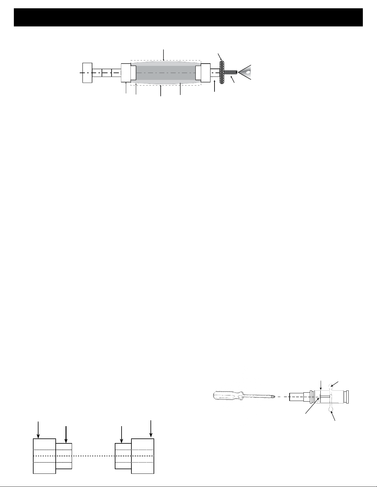
Figure A-Liste des pièces
Embout
Pointe Tube PositionA
FenteA
Bouchon
1-31/32”
PositionB
Ressort de recharge
Recharge
Préparation de l’ébauche
Écrou de torsion
Mécanisme de torsion
Fente B
• Tailler une ébauche selon la longueur du tube de laiton (ajouter 1/16” pour le découpage)
• Percer un trou de 3/8" de diamètre centré longitudinalement dans le centre de l’ébauche.
• Étendre de la colle uniformément sur la face externe du tube de laiton, et insérer, en tournant, ce dernier dans l’ébauche.
Centrer le tube dans l’ébauche et laisser sécher.
• Lorsque la colle est sèche, équarrir les extrémités de l’ébauche. Utiliser un alésoir de 8 mm ou une ponceuse à courroie ou à
disque afin que la longueur de l’ébauche égalise celle du tube de laiton.
• Équarrir jusqu'à ce que la longueur de l’ébauche égalise celle du tube de laiton. Si l’ébauche est plus longue que le tube de
laiton, ceci pourrait empêcher l’assemblage et le bon fonctionnement du mécanisme.
• Utiliser l’alésoir pour le nettoyage intérieur du tube.
PKCP80XX PSI Woodworking Products
FigureB–Tournagedel’ébauche
Ébauche
Tête de tour
de poupée fixe
Écrou de blocage
Contre
pointe
Collets
d’espacement
de 7mm
Mandrin
Tournagedel’ébauche
Embout Tube
Bois
Embout
Collet de 7mm
d’espacement
• Assemblez les collets d’espacement et l’ébauche selon la Figure B.
• Montez l’écrou de blocage et le viser à la main afin de maintenir toutes les composantes en place.
• Visser l’écrou à la main dans le mandrin. Ajuster la poupée mobile sur le mandrin. Ne pas visser trop fermement afin de ne
pas endommager le mandrin.
• Avec des ciseaux bien affutés, tourner l’ébauche jusqu’à ce que ses extrémités atteignent la grandeur du diamètre des
collets. Tourner l’ébauche selon le profil de votre choix.
• Sabler la pièce de bois tournée progressivement, du grain le plus rugueux au grain le plus fin.
• Appliquer la finition choisie. Allouer suffisamment de temps pour que le fini puisse durcir. Se référer aux instructions de
polissage du fini choisi.
Assemblage
• Positionner le verrou soit en position A ou en position B (livré en position A).
• Position A – Vérifier que le verrou soit bien enclenché. Pour resserrer, voir Note 1.
• Position B - Renverser la position du verrou. Voir la Note 1 pour le desserrage/resserrage du verrou.
• Pivoter l’attache vers la fente B (insérer dans la fente). Pour ce faire, enlever le bouchon et pivoter l’attache.
• Replacer le bouchon lorsque le repositionnement est complété.
NOTE: Disposer les pièces finies selon la Figure A
• Insérer la partie avant à l’intérieur de l’un des bouts du tube.
• Insérer la partie arrière au bout opposé du tube.
• Dévisser la pointe et insérer la recharge dans l’ouverture de la
partie avant.
• Insérer le ressort de recharge sur l’embout de la recharge et
replacer la pointe.
• Verrouiller ou déverrouiller le verrou pour allonger ou rétracter la
pointe de la recharge.
NOTE: Veuillez SVP ne pas presser la partie avant de ce
kit si la pointe est enlevée. Cela empêchera le bon
assemblage des morceaux et annulera la garantie.
NOTE 1:
Pivoter et resserrer le verrou.
Pour desserrer et resserrer le
verrou, dévisser ou visser l’écrou
de blocage tel qu’illustré dans la
Figure C. Utiliser un tournevis
Phillips à tête fine, insérer à
l’intérieur tel qu’illustré. Pivoter le
verrou selon la position désirée et
resserrer l’écrou de blocage.
FigureD - Collets
#PKCP3000BU
ø.466” ø.466”
Figure C
Partie arrière
Écrou de blocage
Verrou
Position B
ø.344” ø.344”
Verrou Position A
Trou longitudinal ø.248”
©2012 PSIWoodworkingPhiladelphia PA19115-v12/12
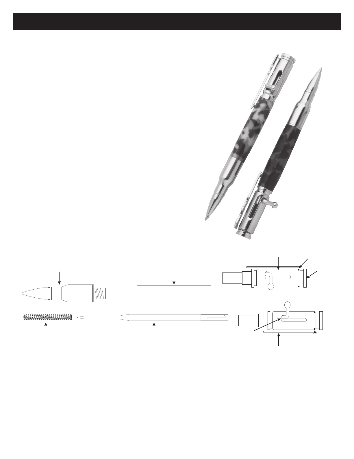
Bolt Action Pen Kit
PKCP80XX
PKCP80XX PSI Woodworking Products
DIAGRAM A - Parts List
Required Accessories:
• 7 mm, pen mandrel
• Drill bit 3/8” #PKEXEC-38
• PKCP3000BU bushing set (2 pc)
• PKTRIMKIT barrel trimming set, use 3/8” sha
• Live Tailstock Center
• 2 part epoxy glue or insta-cure (cyanoacrylate) glue
• Minimum Blank size: 5/8” x 2-1/4”
Preparing the Blank
• Cut one pen blank to the length of the brass tube (add 1/16” for trimming).
• Drill a 3/8” hole lengthwise through the blank.
• Spread the glue over the tube. Insert the tube into the blank with a twisting motion to spread the
glue evenly inside. Center the tube lengthwise in the blank.
• When the glue dries, Square the end of each blank. Use a Barrel trimmer with 3/8” sha or a universal pen
blank squaring jig with a power disc sander. Take the wood down to the brass tube. Do not trim
beyond the length of the tube since this may interfere with operation of the mechanism and assembly.
Use the barrel trimmer sha to clean the inside of the tube.
Kit Features:
• Easy to turn with single tube
• Minimum Parts to assemble
• Uses Parker® Style Rell
• Available Multiple nishes
• Overall length 5-1/4”
• Now with two Bolt positions
Front End Tube / Barrel Position A
Back End Assembly
Position B
Rotate Clip
Rotate Bolt
Threaded Nut
Spring Refill
1-31/32”
Slot B
Slot A
Cap
Position A (as delivered)
Position B (See assembly instructions)
Le Hand Conguration
US PATENT
#D682352S

Turning The Blanks
• Mount the bushings and blank according to Diagram B.
• Thread on the knurled nut and hand tighten to hold all components in place.
• Slide the tailstock up snugly against the mandrel shaft inserting the live center point into the mandrel dimple, lock in place.
• Handtightenthequilladjustmenttormupthemandrel.(DONOTovertighten,itcoulddamagethemandrel.
•Usingsharptools,turntheblankdownclosetothebushingdiameter.Turnthebarrel(straightortoaproleofyourchoice)
• Sandtheblankdowntobeushwiththebushingsgraduallyincreasingthesandpapergrits.
• Finishthebarrelwithyourchoiceofpolish.Allowsufcienttimeforthepolishtocure.-refertopolishinstructions.
DIAGRAM B - Turning the Blanks
© 2012 PSI Woodworking Philadelphia PA 19115 - v12/12
Assembly
•PositionthebolteitherinPositionAorPositionB.(DeliveredinpositionA)
•PositionA-Checktoseeifboltistightlyinplace.TotightenseeNote1
•PositionB-Reversethedirectionofthebolt.SeeNote1onloosening/tighteningthebolt.
•RotatethecliptoslotB(pressintoslot)-dothisbyUnscrewingtheCapandrotatingtheclip.
•Re-attachthecapafterre-positioned
NOTE: Layout Finished parts according to Diagram A
• Press the front end into either end of the barrel.
• Press the back end assembly into the opposite end of the barrel.
• Unscrewthetipandinserttherellintotheopeningatthefrontend.
• Insertthespringovertherellandreplacethetip.
• Lockorunlockthebolttoextendorretracttherelltip.
PKCP80XX PSI Woodworking Products
DIAGRAM D - Bushings
#PKCP3000BU
Blank
7mm spacer
bushings
headstock
mandrel
live
center
knurled nut
wood
barrel
End
bushing
End
bushing
7mm spacer
bushings
ø.466” ø.466”
ø.344” ø.344”
ø.248” hole through
Back End
Set Screw
Bolt Position A
Bolt Position B
NOTE1:
Changingandtighteningthebolt.
To loosen or tighten the bolt,
loosen or tighten the set screw as
shownbelowindiagramC.Take
a long phillips screw driver with a
small head, insert into the back end
asshown.Rotatetheboltasnec-
essary and tighten the set screw.
DIAGRAM C
NOTE: Please do not press the front end of this kit
with the tip removed. If you do so the parts will not
assemble properly and you will void our warranty
Table of contents
Languages:
Other PSI Woodworking Products Tools manuals


